Volumetric Strain, Wire-Wound Cylinders & Joint Efficiency
In this chapter (3 topics)
On this page
- 1. Topic Title & Metadata Header
- 2. Introduction & Physical Mechanics
- 3. Circumferential & Longitudinal Strains in Thin Shells
- 3.1 Circumferential (Diametral) Strain (ε1)
- 3.2 Longitudinal (Axial) Strain (ε2)
- 4. Volumetric Strain of Thin Cylinders and Spherical Shells
- 4.1 Thin Cylindrical Shell Volumetric Strain (εv)
- 4.2 Thin Spherical Shell Volumetric Strain
- 4.3 Quantitative Comparison for Structural Steel (ν = 0.3)
- 5. Hydrostatic Pressure Testing & Fluid Compressibility
- 6. Joint Efficiency in Fabricated Vessels
- 6.1 Longitudinal Joint Efficiency (ηL)
- 6.2 Circumferential Joint Efficiency (ηc)
- 6.3 Rule of Equal Joint Strength
- 7. Wire-Wound Thin Cylinders (Prestressing Mechanics)
- 7.1 Initial Prestress State (Before Fluid Admitted, p = 0)
- 7.2 Working State (Internal Pressure p Admitted)
- 7.3 Final Resultant Stresses
- 8. SVG Technical Illustrations
- 8.1 Volumetric Strain & Dimensional Expansion
- 8.2 Wire-Wound Cylinder Prestressing & Superposition
- 9. Solved Numerical Examples
- Example 9.1: Volumetric Dilatation & Hydrostatic Testing Volume
- Example 9.2: Joint Efficiencies & Safe Working Pressure
- Example 9.3: Wire-Wound Cylinder Prestressing & Stress Reduction
- 10. Indian Standard Code Provisions & Industrial Practice
- 11. Common Misconceptions & High-Yield Exam Traps
- 12. Previous Year Competitive Exam Questions
- Question 1 (GATE CE)
- Question 2 (UPSC ESE)
- Question 3 (SSC JE)
- Question 4 (State AE)
- 13. Comprehensive Summary & Formula Sheet
1. Topic Title & Metadata Header
- Topic ID:
SOM-09-02 - Module / Subject: Strength of Materials (Mechanics of Solids)
- Chapter 09: Thin and Thick Cylinders & Spherical Shells
- Topic Title: Volumetric Strain, Joint Efficiency, and Wire-Wound Thin Cylinders
- Prerequisites:
SOM-01-03(Elastic Constants & Generalized Hooke's Law),SOM-09-01(Thin Cylinder & Spherical Membrane Stresses). - Target Examinations: GATE CE, UPSC ESE (Civil), SSC JE (Civil), State AE/JE, RRB JE (Civil).
- Quality Assurance Gate: Level 1 through Level 7 Verification Protocol Enforced.
2. Introduction & Physical Mechanics
When a thin cylindrical or spherical pressure vessel is subjected to internal fluid pressure, its walls expand elastically under the action of biaxial tensile membrane stresses ( and ). This multi-directional expansion causes three simultaneous dimensional changes:
- Increase in internal diameter (),
- Increase in overall length (),
- Expansion of internal volume ().
Accurate determination of volumetric dilatation is vital in civil and structural engineering:
- Proof & Hydrostatic Acceptance Testing: Water transmission pipelines, penstocks, and pressure vessels are tested by pumping in water to a specified proof pressure (typically operating pressure). Because water is slightly compressible, the total volume of water injected into the vessel during testing equals the vessel volume increase plus the elastic compression volume of the test fluid.
- Joint Efficiency: Fabricated steel pipes and boilers are constructed by rolling steel plates and joining them via longitudinal and circumferential welded or riveted seams. Because joints exhibit lower strength than solid parent metal, joint efficiencies ( and ) directly govern the permissible internal pressure.
- Prestressing via Wire Winding: For high-pressure applications, winding high-tensile wire under tension around a thin cylinder pre-compresses the cylinder wall, significantly reducing tensile hoop stresses during operation. This classical principle is the direct forefather of modern Prestressed Concrete Cylinder Pipes (PCCP / IS 784) and aerospace Composite Overwrapped Pressure Vessels (COPVs).
3. Circumferential & Longitudinal Strains in Thin Shells
Consider an elemental block on the surface of a thin cylindrical pressure vessel subjected to internal gauge pressure . The block is in a state of plane stress with principal stresses:
3.1 Circumferential (Diametral) Strain ()
The circumferential strain represents the fractional change in circumference. For a circular cross-section of initial diameter :
(Fundamental Theorem: Circumferential strain equals diametral strain!)
Applying Generalized Hooke's Law for a biaxial stress field:
Substituting and :
The total increase in internal diameter is:
3.2 Longitudinal (Axial) Strain ()
The longitudinal strain represents the fractional change in length:
Substituting and :
The total increase in length is:
Physical Significance of Poisson's Ratio on Length: Notice the factor :
- If (e.g., structural steel where ), . The cylinder elongates under internal pressure ().
- If an incompressible material were used (), , meaning length remains unchanged ().
- If , the cylinder would actually shorten axially under internal pressure!
4. Volumetric Strain of Thin Cylinders and Spherical Shells
4.1 Thin Cylindrical Shell Volumetric Strain ()
The internal capacity of a cylinder of diameter and length is:
Taking the natural logarithm of both sides:
Differentiating both sides:
In terms of engineering strains:
Now substitute the expressions for and :
The total increase in cylinder capacity is:
4.2 Thin Spherical Shell Volumetric Strain
For a thin spherical shell of diameter , the surface is in a state of uniform equibiaxial tension:
Diametral strain in any direction:
The volume of a sphere is . Taking logarithms and differentiating:
Therefore:
The total volumetric expansion is:
4.3 Quantitative Comparison for Structural Steel ()
- Cylinder:
- Sphere:
5. Hydrostatic Pressure Testing & Fluid Compressibility
During a hydrostatic proof test, the vessel is completely filled with a liquid (usually water) and pressurized using a positive-displacement pump.
Liquids are slightly compressible, characterized by their Bulk Modulus of Elasticity ():
where is the reduction in fluid volume due to compression.
To raise the pressure from to :
- The metal vessel expands by .
- The fluid already inside compresses, requiring additional liquid to occupy that compressed space.
The total volume of liquid required to be pumped in () is the sum:
For water, . In long municipal pipelines, the fluid compression volume often equals or exceeds the metal expansion volume!
6. Joint Efficiency in Fabricated Vessels
Commercial pressure vessels and pipes are fabricated by rolling flat steel plates into cylinders and joining them by welding or riveting. Because joints contain heat-affected zones, microscopic flaws, or rivet holes, they are weaker than the seamless parent metal.
This weakness is quantified by the Joint Efficiency factor ():
6.1 Longitudinal Joint Efficiency ()
A longitudinal seam runs parallel to the axis of the cylinder. As demonstrated in SOM-09-01, circumferential (hoop) stress acts perpendicular to this seam, attempting to tear it apart:
Therefore, the permissible pressure governed by the longitudinal joint is:
6.2 Circumferential Joint Efficiency ()
A circumferential (girth) seam runs around the circumference of the cylinder. Longitudinal stress acts perpendicular to this seam:
Therefore, the permissible pressure governed by the circumferential joint is:
6.3 Rule of Equal Joint Strength
Equating the allowable pressures :
Key Fabrication Rule: To provide equal safety against bursting, the circumferential joint needs to have only half the efficiency of the longitudinal joint ().
- Longitudinal joints are typically full-penetration double-welded butt joints with radiographic examination ().
- Circumferential joints can use single-welded joints or spot radiography ().
7. Wire-Wound Thin Cylinders (Prestressing Mechanics)
For high-pressure conduits, guns, and hydraulic cylinders, the required wall thickness becomes large, reducing structural efficiency and risking brittle fracture.
To overcome this limitation, a thin cylinder can be prestressed by winding high-tensile steel wire around its exterior under initial tension .
  INITIAL STATE (p = 0):
  Wire in Tension (+σ_w0)  ======>  Puts Cylinder Wall into Compression (-σ_c0)

  WORKING STATE (Fluid Pressure p admitted):
  Fluid Pressure creates Tensile Increment (+Δσ) in both Wall and Wire
  Resultant Cylinder Stress = Δσ - σ_c0  (Greatly reduced tension!)
  Resultant Wire Stress     = σ_w0 + Δσ  (Safe in high-strength wire)
7.1 Initial Prestress State (Before Fluid Admitted, )
Let:
- internal diameter of cylinder,
- wall thickness of cylinder,
- diameter of wire, wound at pitch (for tight coil, ),
- equivalent cross-sectional area of wire per unit length of cylinder:
- initial tensile winding stress in wire,
- initial compressive stress induced in cylinder wall.
Consider a longitudinal cut of unit length (). Equating total wire tensile force to cylinder compressive force:
7.2 Working State (Internal Pressure Admitted)
When fluid pressure is admitted, the cylinder expands radially. By displacement compatibility, the wire and cylinder wall must experience identical circumferential strain increments:
Neglecting the Poisson effect from longitudinal stress (standard for wire-wound analysis):
where is the modular ratio (if wire and cylinder are the same material, , and ).
Equilibrium of bursting force per unit length:
Equating forces:
If ():
7.3 Final Resultant Stresses
- In the Cylinder Wall:
- In the Wire:
8. SVG Technical Illustrations
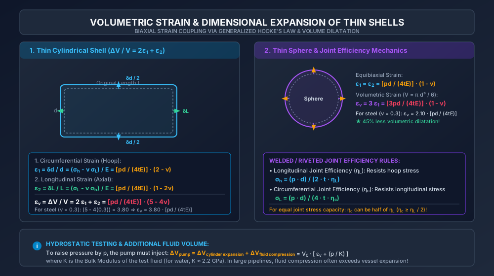
8.1 Volumetric Strain & Dimensional Expansion
The illustration below demonstrates diametral and longitudinal expansions under pressure, the logarithmic derivation of volumetric strain, and joint efficiency mechanics.
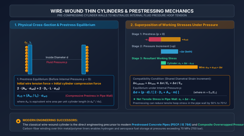
8.2 Wire-Wound Cylinder Prestressing & Superposition
The diagram below details the physical cross-section of wire-wound cylinders, the equilibrium of initial winding tension, and the 3-stage stress superposition resulting in dramatic wall stress reduction.
9. Solved Numerical Examples
Example 9.1: Volumetric Dilatation & Hydrostatic Testing Volume
Problem Statement:
A thin cylindrical water pipe has an internal diameter of , length (), and wall thickness . The pipe is subjected to an internal hydrostatic test pressure of ().
Given: Steel modulus , Poisson's ratio , and Bulk Modulus of water .
- Calculate the circumferential and longitudinal strains.
- Calculate the change in internal diameter and change in length .
- Calculate the volumetric strain and the physical volume increase of the pipe .
- Calculate the additional volume of water that must be pumped in to reach test pressure, accounting for the compressibility of water.
Step-by-Step Solution:
-
Membrane Stresses:
-
Circumferential & Longitudinal Strains:
-
Dimensional Changes:
-
Volumetric Dilatation:
- Volumetric Strain: (Alternatively: ).
- Initial Volume ():
- Volume Increase of Pipe ():
-
Additional Water to be Pumped In:
- Water volume compression:
- Total Water Injected:
(Engineering Observation: Fluid compressibility accounts for of the total water injected by the pump during the test!).
Example 9.2: Joint Efficiencies & Safe Working Pressure
Problem Statement:
A fabricated cylindrical steel boiler shell has an internal diameter of () and a wall thickness of . The plates are joined by longitudinal and circumferential riveted seams with joint efficiencies:
- Longitudinal joint efficiency:
- Circumferential joint efficiency: The maximum permissible tensile stress in the steel plate is . Determine:
- The safe working pressure limited by the longitudinal joint.
- The safe working pressure limited by the circumferential joint.
- The overall safe working pressure of the boiler and specify which joint governs.
Step-by-Step Solution:
-
Pressure Limited by Longitudinal Joint (): The longitudinal joint resists hoop stress :
-
Pressure Limited by Circumferential Joint (): The circumferential joint resists longitudinal stress :
-
Governing Safe Working Pressure:
Critical Exam Takeaway: Although the circumferential joint efficiency is much lower ( vs. ), the longitudinal joint still governs failure because the hoop bursting force is twice as large as the axial bursting force!
For the circumferential joint to govern, its efficiency would have to drop below ().
Example 9.3: Wire-Wound Cylinder Prestressing & Stress Reduction
Problem Statement:
A cast-iron pipe of internal diameter and wall thickness is closely wound with a single layer of high-tensile steel wire of diameter under an initial tensile winding stress of . The wire coils touch each other tightly (pitch ).
An internal fluid pressure of is then admitted into the pipe.
Assume .
- Calculate the initial compressive hoop stress induced in the pipe wall before fluid is admitted.
- Calculate the stress increment in the wall and wire upon application of internal fluid pressure.
- Determine the final resultant hoop stress in the pipe wall and the final tensile stress in the wire.
- Calculate what the tensile stress in the pipe wall would have been if there had been no wire winding, and find the percentage reduction in tensile stress achieved.
Step-by-Step Solution:
-
Geometry of Winding: For a tightly wound layer of pitch , each length of pipe carries wire coil.
Equivalent cross-sectional area of wire per millimetre length of cylinder: -
Initial Prestress in Pipe Wall (): Equating wire tension to pipe wall compression on length:
-
Stress Increment from Fluid Pressure (): Because , strain compatibility gives .
Total bursting force on length:Resisting force on length:
Equating :
-
Final Working Stresses:
- Net Stress in Pipe Wall:
- Net Stress in Wire:
-
Comparison with Plain (Unwound) Cylinder: If the pipe had not been wire-wound:
- Stress Reduction Achieved:
(Conclusion: Wire winding slashes the peak tensile stress in the cast iron cylinder wall from to just , preventing brittle bursting while safely transferring the high tensile load to high-strength steel wire).
10. Indian Standard Code Provisions & Industrial Practice
-
IS 2825:1969 (Code for Unfired Pressure Vessels):
- Mandates joint efficiencies () based on weld inspection category:
- Class 1 vessels: Full radiographed welds .
- Class 2 vessels: Spot radiographed welds .
- Class 3 vessels: Visual inspection only .
- Shell thickness formula incorporating joint efficiency and static corrosion allowance ():
- Mandates joint efficiencies () based on weld inspection category:
-
IS 784:2001 (Prestressed Concrete Pipes — Specification):
- Applies the wire-winding prestress principle directly to concrete water mains (PCCP).
- High-tensile steel wire (IS 1785) is helically wrapped under high tension around a concrete core pipe to induce circumferential pre-compression.
- The pre-compression ensures that under maximum surge and working pressure, the concrete core remains strictly in compression, preventing cracking and leakage.
-
ASME BPVC Section VIII Division 1 (UW-12):
- Details Type 1 (butt joints with full penetration), Type 2 (single welded with backing strip), and Type 3 (single welded butt without backing strip), establishing explicit joint efficiency tables for longitudinal vs. circumferential seams.
11. Common Misconceptions & High-Yield Exam Traps
-
Forgetting Poisson's Coupling in Circumferential Strain:
- Trap: Writing .
- Correction: The vessel is under biaxial tension. Circumferential expansion is partially constrained by longitudinal tension via Poisson's ratio: .
-
Confusing Volume Dilatation Factor with :
- Trap: Mis-deriving .
- Correction: .
-
Assuming Longitudinal Joint Resists Longitudinal Stress:
- Trap: Applying to calculate longitudinal stress .
- Correction: The longitudinal joint runs lengthwise; it splits open under hoop stress. Hence, modifies hoop stress , and modifies longitudinal stress !
-
Ignoring Fluid Compressibility in Hydrostatic Test Calculations:
- Trap: Calculating the water needed to raise pressure by computing only the vessel expansion .
- Correction: Liquid is compressible (). The pump must supply .
-
Believing Winding Wire Reduces Longitudinal Stress:
- Trap: Thinking wire coils reduce longitudinal stress .
- Correction: Wires are wound around the circumference; they act purely in the hoop direction. Wire winding reduces hoop stress only; longitudinal stress remains .
12. Previous Year Competitive Exam Questions
Question 1 (GATE CE)
A thin cylindrical shell of diameter , length , and thickness is subjected to internal pressure . The Poisson's ratio of the material is and Young's modulus is . The ratio of circumferential strain to longitudinal strain is:
- (A)
- (B)
- (C)
- (D)
Answer: (B)
Solution:
, .
Ratio .
Question 2 (UPSC ESE)
For an incompressible material (), what is the longitudinal strain in a thin cylindrical pressure vessel subjected to internal pressure?
- (A)
- (B)
- (C) Zero
- (D) Negative
Answer: (C)
Solution:
. Setting .
Question 3 (SSC JE)
A thin spherical shell of diameter , thickness , Young's modulus , and Poisson's ratio is subjected to internal pressure . The volumetric strain of the sphere is:
- (A)
- (B)
- (C)
- (D)
Answer: (A)
Solution:
In a sphere, . Since , .
Question 4 (State AE)
In a cylindrical boiler, the longitudinal joint has an efficiency of . To have the same factor of safety in both seams, the circumferential joint efficiency should be at least:
- (A)
- (B)
- (C)
- (D)
Answer: (C)
Solution:
For equal allowable pressure: .
13. Comprehensive Summary & Formula Sheet
| Parameter / Phenomenon | Mathematical Formula | Key Assumptions & Conditions |
|---|---|---|
| Circumferential Strain () | Plane stress Hooke's Law, thin shell () | |
| Longitudinal Strain () | Closed ends, axial stress present | |
| Cylinder Volumetric Strain () | Sum of principal strains: | |
| Sphere Volumetric Strain () | Equibiaxial expansion: | |
| Fluid Compression Volume () | Bulk modulus of test liquid (water ) | |
| Total Test Injection Volume | Critical for hydrostatic pipeline commissioning | |
| Longitudinal Joint Stress | longitudinal weld/rivet joint efficiency | |
| Circumferential Joint Stress | circumferential weld/rivet joint efficiency | |
| Equal Joint Strength Rule | Circumferential joint needs only half efficiency | |
| Initial Wire Prestress in Wall | Initial compression in pipe wall () | |
| Pressure Stress Increment () | Shared strain compatibility condition () | |
| Net Wall Stress in Wire-Wound Pipe | Tensile stress reduced by initial compression |