SOM-02-05 Chapter 02 · Principal Stresses and Strains

Theories of Elastic Failure & Yield Criteria

In this chapter (5 topics)
On this page
  1. 1. Metadata & Syllabus Mapping
  2. Official Examination Syllabus Mapping
  3. 2. Introduction & Physical Mechanics
  4. The Fundamental Question:
  5. Modes of Failure:
  6. 3. Mathematical Formulations & Derivations
  7. 3.1 Theory 1: Maximum Principal Stress Theory (Rankine's Theory)
  8. 3.2 Theory 2: Maximum Shear Stress Theory (Tresca / Guest / Coulomb Theory)
  9. 3.3 Theory 3: Maximum Principal Strain Theory (Saint-Venant's Theory)
  10. 3.4 Theory 4: Maximum Total Strain Energy Theory (Haigh's Theory / Beltrami)
  11. 3.5 Theory 5: Maximum Distortion Energy Theory (von Mises / Hencky / Octahedral Shear)
  12. 3.6 Equivalence to Octahedral Shear Stress Theory
  13. 3.7 Combined Bending and Torsion under Failure Theories
  14. 4. Engineering Assumptions & Limitations
  15. 5. Technical Diagrams
  16. Diagram 1: Comparative 2D Yield Loci in Plane Stress
  17. Diagram 2: Octahedral Shear Stress & Stress Decomposition
  18. 6. Solved Numerical Examples
  19. Example 5.1: Multi-Theory Evaluation of Factor of Safety
  20. Example 5.2: Shaft Sizing under Combined Bending and Torsion
  21. Example 5.3: Hydrostatic Invariance of Octahedral Shear Stress
  22. 7. Practical & Field Engineering Applications
  23. 8. Comparative Analysis
  24. Exhaustive Failure Theories Comparison Matrix
  25. 9. Key Engineering Facts & Exam Takeaways
  26. 10. Common Pitfalls, Traps & Anti-Patterns
  27. 11. Standards & Code Provisions
  28. IS 800:2007 (General Construction in Steel - Code of Practice)
  29. IS 456:2000 (Plain and Reinforced Concrete - Code of Practice)
  30. ASME Boiler and Pressure Vessel Code (Section VIII, Division 2)
  31. 12. Comprehensive Formula Box & Practice Problems
  32. Master Formula Summary
  33. Practice Problems

1. Metadata & Syllabus Mapping

Attribute Specification
Topic ID SOM-02-05
Module / Subject Subject 02: Strength of Materials (notes/strength_of_materials/)
Chapter Chapter 02: Principal Stresses and Strains (02_principal_stresses_and_strains)
Target Examinations GATE CE, UPSC ESE, SSC JE, RRB JE, State AE, State JE
Prerequisites SOM-01-01 (Stress & Strain), SOM-01-03 (Elastic Constants), SOM-02-02 (Principal Stresses), SOM-02-03 (Mohr's Circle)
Primary Code References IS 800:2007 Clause 9.3 (von Mises Yield Criterion), IS 456:2000 (Rankine Tension Cracking), ASME BPVC Section VIII
Verification Gate Level 1 through Level 7 Quality Standards

Official Examination Syllabus Mapping

Website note: this mapping is from the author’s notes. It has not been checked against the official notification for each examination; confirm the current syllabus with the examining body.

- GATE Civil Engineering: Solid Mechanics — Theories of failures (Maximum principal stress, maximum shear stress, maximum principal strain, maximum strain energy, distortion energy / von Mises theory); graphical representation of failure envelopes in plane stress; factor of safety; pure shear yield strength.
- UPSC ESE (Engineering Services): Paper-I Solid Mechanics — Comparative study of failure theories for ductile and brittle materials; Octahedral shear stress theory; equivalent bending and twisting moments under Tresca and von Mises; design of shafts and pressure vessels.
- SSC JE / RRB JE / State AE: Names, criteria, and 2D shapes of failure envelopes (Square, Hexagon, Rhombus, Ellipse); ratio of yield strength in shear to yield strength in tension (0.50 vs 0.577); choice of theory for cast iron, concrete, and mild steel.

2. Introduction & Physical Mechanics

In simple uniaxial tension tests (e.g., standard standard tensile testing on a UTM), determining when a material fails is straightforward: failure initiates when the uniaxial stress σ\sigma reaches the yield strength fyf_y (for ductile materials) or the ultimate tensile strength fuf_u (for brittle materials).

However, in real civil engineering structures—such as continuous bridge girders, arch dams, turbine shafts, thin-walled storage tanks, and bolted joint gusset plates—structural elements are subjected to complex multiaxial (biaxial or triaxial) stress states (σ1,σ2,σ3)(\sigma_1, \sigma_2, \sigma_3) where tensile, compressive, and shear stresses act concurrently.

The Fundamental Question:

Under what mathematical combination of multiaxial principal stresses (σ1,σ2,σ3)(\sigma_1, \sigma_2, \sigma_3) will a material begin to yield or fracture, given only its yield strength fyf_y determined from a simple uniaxial tension test?

To answer this question, elasticians formulated Theories of Elastic Failure (also termed Yield Criteria). Each theory posits that inelastic failure initiates when a specific physical quantity in the multiaxial stress state reaches the corresponding critical value that causes failure in a standard uniaxial tensile specimen.

Modes of Failure:

  1. Yielding (Ductile Slip): Characterized by extensive plastic slip along shear planes without volume change (observed in structural mild steel, copper, aluminum). Governed by shear and distortion energy theories (Tresca, von Mises).
  2. Brittle Fracture (Cleavage / Separation): Characterized by rapid crack propagation across planes of maximum normal tension without noticeable plastic deformation (observed in plain concrete, masonry, cast iron, glass, rock). Governed by maximum principal stress theory (Rankine).

3. Mathematical Formulations & Derivations

Let fyf_y be the yield strength of the material in simple uniaxial tension, and FOS\text{FOS} be the design Factor of Safety. The allowable tensile stress is:

σallow=fyFOS(Eq. 5.1)\sigma_{\text{allow}} = \frac{f_y}{\text{FOS}} \tag{Eq. 5.1}

In a uniaxial tension test at the onset of yield:

σ1=fy,σ2=0,σ3=0(Eq. 5.2)\sigma_1 = f_y, \quad \sigma_2 = 0, \quad \sigma_3 = 0 \tag{Eq. 5.2}

We examine the five classical theories of failure:


3.1 Theory 1: Maximum Principal Stress Theory (Rankine's Theory)

Proposed By: William John Macquorn Rankine (1857).

Core Hypothesis:

Inelastic failure initiates when the algebraically largest principal tensile stress (σ1\sigma_1) reaches the yield or ultimate tensile strength in uniaxial tension, or when the largest compressive stress (∣σ3∣|\sigma_3|) reaches the uniaxial compressive strength.

Mathematical Criterion:

σ1≤fyFOSand∣σ3∣≤fcFOS(Eq. 5.3)\mathbf{\sigma_1 \le \frac{f_y}{\text{FOS}}} \quad \text{and} \quad \mathbf{|\sigma_3| \le \frac{f_c}{\text{FOS}}} \tag{Eq. 5.3}

In a 2D state of plane stress (σ3=0\sigma_3 = 0), assuming equal tensile and compressive strengths (fy=fcf_y = f_c):

−fy≤σ1≤+fy(Eq. 5.4a)-f_y \le \sigma_1 \le +f_y \tag{Eq. 5.4a} −fy≤σ2≤+fy(Eq. 5.4b)-f_y \le \sigma_2 \le +f_y \tag{Eq. 5.4b}

2D Failure Locus:

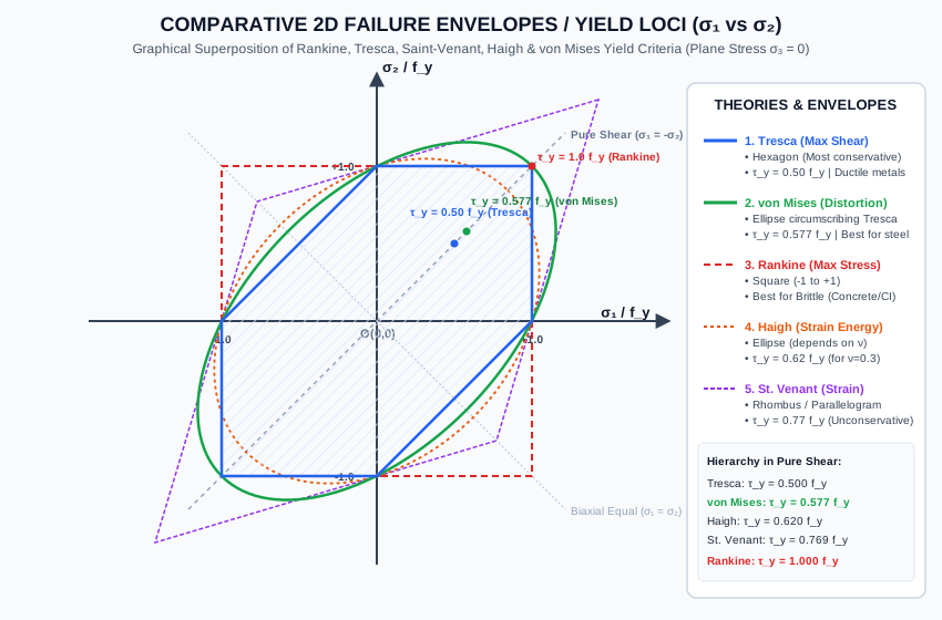
The failure boundary in the (σ1,σ2)(\sigma_1, \sigma_2) plane is a Square centered at the origin with side length 2fy2f_y.

Pure Shear Yield Strength (τy\tau_y):

In pure shear: σ1=+τ,σ2=−τ,σ3=0\sigma_1 = +\tau, \sigma_2 = -\tau, \sigma_3 = 0.
According to Rankine: σ1=τ≤fy  ⟹  τy=fy=1.0fy\sigma_1 = \tau \le f_y \implies \mathbf{\tau_y = f_y = 1.0 f_y}.

Critical Evaluation: Predicting τy=1.0fy\tau_y = 1.0 f_y grossly overestimates the shear capacity of ductile metals (experiments show steel yields in shear at τy≈0.50 to 0.58fy\tau_y \approx 0.50 \text{ to } 0.58 f_y). Rankine's theory is extremely dangerous and unsafe for ductile materials, but provides excellent predictions for brittle materials (concrete, cast iron, stone) failing by cleavage under tension.


3.2 Theory 2: Maximum Shear Stress Theory (Tresca / Guest / Coulomb Theory)

Proposed By: Henri Tresca (1864) and James Guest (1900).

Core Hypothesis:

Inelastic failure (plastic yielding) initiates when the absolute maximum shear stress in the multiaxial stress state reaches the maximum shear stress developed at yield in a standard uniaxial tension test.

Uniaxial Benchmark:

In simple tension at yield (σ1=fy,σ2=0,σ3=0\sigma_1 = f_y, \sigma_2 = 0, \sigma_3 = 0):

τmax⁡,uniaxial=σ1−σ32=fy−02=fy2(Eq. 5.5)\tau_{\max, \text{uniaxial}} = \frac{\sigma_1 - \sigma_3}{2} = \frac{f_y - 0}{2} = \frac{f_y}{2} \tag{Eq. 5.5}

Mathematical Criterion (3D):

τabs, max=max⁡(∣σ1−σ2∣2,∣σ2−σ3∣2,∣σ3−σ1∣2)≤fy2⋅FOS(Eq. 5.6)\mathbf{\tau_{\text{abs, max}} = \max\left(\frac{|\sigma_1 - \sigma_2|}{2}, \frac{|\sigma_2 - \sigma_3|}{2}, \frac{|\sigma_3 - \sigma_1|}{2}\right) \le \frac{f_y}{2 \cdot \text{FOS}}} \tag{Eq. 5.6}

2D State of Plane Stress (σ3=0\sigma_3 = 0):

The three principal stresses are σ1,σ2,0\sigma_1, \sigma_2, 0. Two distinct regimes exist:

  1. Same Sign (Q1Q_1 and Q3Q_3: Biaxial Tension or Biaxial Compression):

    • If σ1>σ2>0\sigma_1 > \sigma_2 > 0: τabs, max=σ1−02=σ12≤fy2  ⟹  σ1≤fy\tau_{\text{abs, max}} = \frac{\sigma_1 - 0}{2} = \frac{\sigma_1}{2} \le \frac{f_y}{2} \implies \mathbf{\sigma_1 \le f_y}.
    • If 0>σ1>σ20 > \sigma_1 > \sigma_2: τabs, max=0−σ22=∣σ2∣2≤fy2  ⟹  ∣σ2∣≤fy\tau_{\text{abs, max}} = \frac{0 - \sigma_2}{2} = \frac{|\sigma_2|}{2} \le \frac{f_y}{2} \implies \mathbf{|\sigma_2| \le f_y}. (The boundary lines are parallel to the coordinate axes).
  2. Opposite Signs (Q2Q_2 and Q4Q_4: Tension-Compression):

    • If σ1>0>σ2\sigma_1 > 0 > \sigma_2: τabs, max=σ1−σ22≤fy2  ⟹  σ1−σ2≤fy\tau_{\text{abs, max}} = \frac{\sigma_1 - \sigma_2}{2} \le \frac{f_y}{2} \implies \mathbf{\sigma_1 - \sigma_2 \le f_y}. (The boundary lines are slanted at 45∘45^\circ).

2D Failure Locus:

The failure boundary in the (σ1,σ2)(\sigma_1, \sigma_2) plane is an irregular Hexagon (The Tresca Hexagon) inscribed inside the Rankine square.

Pure Shear Yield Strength (τy\tau_y):

In pure shear: σ1=+τ,σ2=−τ\sigma_1 = +\tau, \sigma_2 = -\tau.

τabs, max=σ1−σ22=τ−(−τ)2=τ≤fy2  ⟹  τy=fy2=0.50fy(Eq. 5.7)\tau_{\text{abs, max}} = \frac{\sigma_1 - \sigma_2}{2} = \frac{\tau - (-\tau)}{2} = \tau \le \frac{f_y}{2} \implies \mathbf{\tau_y = \frac{f_y}{2} = 0.50 f_y} \tag{Eq. 5.7}

Critical Evaluation: Tresca's theory is the most conservative yield criterion for ductile metals. It is simple to apply and guarantees safe, lower-bound designs in structural steel and mechanical shafts.


3.3 Theory 3: Maximum Principal Strain Theory (Saint-Venant's Theory)

Proposed By: Adhémar Jean Claude Barré de Saint-Venant (1837).

Core Hypothesis:

Failure initiates when the maximum principal tensile strain reaches the yield strain in simple tension (ϵmax⁡≤ϵy=fyE\epsilon_{\max} \le \epsilon_y = \frac{f_y}{E}).

Mathematical Criterion:

Under Generalized Hooke's Law for 3D stresses:

ϵ1=1E[σ1−ν(σ2+σ3)]≤fyE⋅FOS\epsilon_1 = \frac{1}{E}\left[\sigma_1 - \nu(\sigma_2 + \sigma_3)\right] \le \frac{f_y}{E \cdot \text{FOS}} σ1−ν(σ2+σ3)≤fyFOS(Eq. 5.8)\mathbf{\sigma_1 - \nu(\sigma_2 + \sigma_3) \le \frac{f_y}{\text{FOS}}} \tag{Eq. 5.8}

For plane stress (σ3=0\sigma_3 = 0):

σ1−νσ2≤fyFOSandσ2−νσ1≤fyFOS(Eq. 5.9)\mathbf{\sigma_1 - \nu \sigma_2 \le \frac{f_y}{\text{FOS}}} \quad \text{and} \quad \mathbf{\sigma_2 - \nu \sigma_1 \le \frac{f_y}{\text{FOS}}} \tag{Eq. 5.9}

2D Failure Locus:

The failure boundary in the (σ1,σ2)(\sigma_1, \sigma_2) plane is a Rhombus (Parallelogram) with diagonals oriented along σ1=σ2\sigma_1 = \sigma_2 and σ1=−σ2\sigma_1 = -\sigma_2.

Pure Shear Yield Strength (τy\tau_y):

In pure shear (σ1=τ,σ2=−τ\sigma_1 = \tau, \sigma_2 = -\tau):

σ1−νσ2=τ−ν(−τ)=τ(1+ν)≤fy  ⟹  τy=fy1+ν(Eq. 5.10)\sigma_1 - \nu \sigma_2 = \tau - \nu(-\tau) = \tau(1 + \nu) \le f_y \implies \mathbf{\tau_y = \frac{f_y}{1 + \nu}} \tag{Eq. 5.10}

For steel (ν=0.30\nu = 0.30): τy=fy1.30≈0.769fy\tau_y = \frac{f_y}{1.30} \approx 0.769 f_y.

Critical Evaluation: Predicting τy≈0.77fy\tau_y \approx 0.77 f_y is significantly unconservative for ductile metals. Saint-Venant's theory has historical importance but is not recommended in modern structural design codes.


3.4 Theory 4: Maximum Total Strain Energy Theory (Haigh's Theory / Beltrami)

Proposed By: Bernard Parker Haigh (1919) and Eugenio Beltrami (1885).

Core Hypothesis:

Inelastic failure initiates when the total elastic strain energy absorbed per unit volume (UU) reaches the strain energy absorbed per unit volume at yield in simple tension (UyU_y).

Uniaxial Benchmark:

In simple tension at yield (σ1=fy,σ2=σ3=0\sigma_1 = f_y, \sigma_2 = \sigma_3 = 0):

Uy=12σ1ϵ1=fy22E(Eq. 5.11)U_y = \frac{1}{2}\sigma_1 \epsilon_1 = \frac{f_y^2}{2E} \tag{Eq. 5.11}

3D Mathematical Formulation:

The total elastic strain energy per unit volume is:

U=12E[σ12+σ22+σ32−2ν(σ1σ2+σ2σ3+σ3σ1)]≤fy22E⋅FOS2U = \frac{1}{2E}\left[\sigma_1^2 + \sigma_2^2 + \sigma_3^2 - 2\nu(\sigma_1\sigma_2 + \sigma_2\sigma_3 + \sigma_3\sigma_1)\right] \le \frac{f_y^2}{2E \cdot \text{FOS}^2} σ12+σ22+σ32−2ν(σ1σ2+σ2σ3+σ3σ1)≤(fyFOS)2(Eq. 5.12)\mathbf{\sigma_1^2 + \sigma_2^2 + \sigma_3^2 - 2\nu(\sigma_1\sigma_2 + \sigma_2\sigma_3 + \sigma_3\sigma_1) \le \left(\frac{f_y}{\text{FOS}}\right)^2} \tag{Eq. 5.12}

In 2D plane stress (σ3=0\sigma_3 = 0):

σ12+σ22−2νσ1σ2≤(fyFOS)2(Eq. 5.13)\mathbf{\sigma_1^2 + \sigma_2^2 - 2\nu \sigma_1 \sigma_2 \le \left(\frac{f_y}{\text{FOS}}\right)^2} \tag{Eq. 5.13}

2D Failure Locus:

The failure boundary in the (σ1,σ2)(\sigma_1, \sigma_2) plane is an Ellipse inclined at 45∘45^\circ, whose dimensions depend on Poisson's ratio ν\nu.

Pure Shear Yield Strength (τy\tau_y):

In pure shear (σ1=τ,σ2=−τ\sigma_1 = \tau, \sigma_2 = -\tau):

τ2+(−τ)2−2ν(τ)(−τ)=2τ2(1+ν)≤fy2\tau^2 + (-\tau)^2 - 2\nu(\tau)(-\tau) = 2\tau^2(1 + \nu) \le f_y^2 τy=fy2(1+ν)(Eq. 5.14)\mathbf{\tau_y = \frac{f_y}{\sqrt{2(1 + \nu)}}} \tag{Eq. 5.14}

For steel (ν=0.30\nu = 0.30): τy=fy2(1.30)=fy2.60≈0.620fy\tau_y = \frac{f_y}{\sqrt{2(1.30)}} = \frac{f_y}{\sqrt{2.60}} \approx 0.620 f_y.

Critical Flaw: Haigh's theory includes volumetric energy. Under very high hydrostatic compression (σ1=σ2=σ3=−p\sigma_1 = \sigma_2 = \sigma_3 = -p), huge strain energy accumulates, predicting failure even though hydrostatic pressure never causes yielding in metals (Bridgman's high-pressure physics experiments).


3.5 Theory 5: Maximum Distortion Energy Theory (von Mises / Hencky / Octahedral Shear)

Proposed By: Richard von Mises (1913), Heinrich Hencky (1924), and Maksymilian Tytus Huber (1904).

Physical Foundation:

Elastic strain energy per unit volume can be partitioned into two distinct physical components:

Utotal=Uv (Volumetric Dilatation Energy)+Ud (Distortion / Shear Energy)(Eq. 5.15)U_{\text{total}} = U_v\ (\text{Volumetric Dilatation Energy}) + U_d\ (\text{Distortion / Shear Energy}) \tag{Eq. 5.15}
  1. Volumetric Strain Energy (UvU_v): Caused by the hydrostatic (mean normal) stress σm=σ1+σ2+σ33\sigma_m = \frac{\sigma_1 + \sigma_2 + \sigma_3}{3}. It changes volume without altering shape and cannot cause plastic slip or dislocation movement in crystals.

    Uv=1−2ν6E(σ1+σ2+σ3)2(Eq. 5.16)U_v = \frac{1 - 2\nu}{6E}\left(\sigma_1 + \sigma_2 + \sigma_3\right)^2 \tag{Eq. 5.16}
  2. Distortion Strain Energy (UdU_d): Caused by the deviatoric stress tensor (sij=σij−σmδijs_{ij} = \sigma_{ij} - \sigma_m \delta_{ij}). It distorts the crystal lattice and drives ductile shear yielding.

    Ud=Utotal−Uv=1+ν6E[(σ1−σ2)2+(σ2−σ3)2+(σ3−σ1)2]U_d = U_{\text{total}} - U_v = \frac{1 + \nu}{6E}\left[(\sigma_1 - \sigma_2)^2 + (\sigma_2 - \sigma_3)^2 + (\sigma_3 - \sigma_1)^2\right]

    Using G=E2(1+ν)G = \frac{E}{2(1 + \nu)}:

    Ud=112G[(σ1−σ2)2+(σ2−σ3)2+(σ3−σ1)2](Eq. 5.17)\mathbf{U_d = \frac{1}{12G}\left[(\sigma_1 - \sigma_2)^2 + (\sigma_2 - \sigma_3)^2 + (\sigma_3 - \sigma_1)^2\right]} \tag{Eq. 5.17}

Uniaxial Benchmark:

In simple tension at yield (σ1=fy,σ2=σ3=0\sigma_1 = f_y, \sigma_2 = \sigma_3 = 0):

Ud,y=112G[(fy−0)2+(0−0)2+(0−fy)2]=2fy212G=fy26G(Eq. 5.18)U_{d,y} = \frac{1}{12G}\left[(f_y - 0)^2 + (0 - 0)^2 + (0 - f_y)^2\right] = \frac{2f_y^2}{12G} = \frac{f_y^2}{6G} \tag{Eq. 5.18}

Mathematical Criterion:

Equating Ud≤Ud,y/FOS2U_d \le U_{d,y} / \text{FOS}^2:

112G[(σ1−σ2)2+(σ2−σ3)2+(σ3−σ1)2]≤16G(fyFOS)2\frac{1}{12G}\left[(\sigma_1 - \sigma_2)^2 + (\sigma_2 - \sigma_3)^2 + (\sigma_3 - \sigma_1)^2\right] \le \frac{1}{6G}\left(\frac{f_y}{\text{FOS}}\right)^2 (σ1−σ2)2+(σ2−σ3)2+(σ3−σ1)2≤2(fyFOS)2(Eq. 5.19)\mathbf{(\sigma_1 - \sigma_2)^2 + (\sigma_2 - \sigma_3)^2 + (\sigma_3 - \sigma_1)^2 \le 2\left(\frac{f_y}{\text{FOS}}\right)^2} \tag{Eq. 5.19}

Defining the Equivalent von Mises Stress (σv\sigma_v):

σv=12(σ1−σ2)2+(σ2−σ3)2+(σ3−σ1)2≤fyFOS(Eq. 5.20)\mathbf{\sigma_v = \frac{1}{\sqrt{2}}\sqrt{(\sigma_1 - \sigma_2)^2 + (\sigma_2 - \sigma_3)^2 + (\sigma_3 - \sigma_1)^2} \le \frac{f_y}{\text{FOS}}} \tag{Eq. 5.20}

Plane Stress Formulation (σ3=0\sigma_3 = 0):

Setting σ3=0\sigma_3 = 0 in Eq. (5.19):

(σ1−σ2)2+σ22+σ12≤2(fyFOS)2(\sigma_1 - \sigma_2)^2 + \sigma_2^2 + \sigma_1^2 \le 2\left(\frac{f_y}{\text{FOS}}\right)^2 2σ12−2σ1σ2+2σ22≤2(fyFOS)22\sigma_1^2 - 2\sigma_1\sigma_2 + 2\sigma_2^2 \le 2\left(\frac{f_y}{\text{FOS}}\right)^2 σ12−σ1σ2+σ22≤(fyFOS)2(Eq. 5.21)\mathbf{\sigma_1^2 - \sigma_1 \sigma_2 + \sigma_2^2 \le \left(\frac{f_y}{\text{FOS}}\right)^2} \tag{Eq. 5.21}

In general Cartesian stress components (σx,σy,τxy)(\sigma_x, \sigma_y, \tau_{xy}):

σv=σx2−σxσy+σy2+3τxy2≤fyFOS(Eq. 5.22)\mathbf{\sigma_v = \sqrt{\sigma_x^2 - \sigma_x \sigma_y + \sigma_y^2 + 3\tau_{xy}^2} \le \frac{f_y}{\text{FOS}}} \tag{Eq. 5.22}

(This is the exact yield verification equation mandated in IS 800:2007 Clause 9.3).

2D Failure Locus:

The failure boundary in the (σ1,σ2)(\sigma_1, \sigma_2) plane is an Ellipse inclined at 45∘45^\circ, perfectly circumscribing the Tresca hexagon.

  • Major axis along σ1=σ2\sigma_1 = \sigma_2: length 22fy2\sqrt{2} f_y.
  • Minor axis along σ1=−σ2\sigma_1 = -\sigma_2: length 22/3fy2\sqrt{2/3} f_y.

Pure Shear Yield Strength (τy\tau_y):

In pure shear (σ1=τ,σ2=−τ,σ3=0\sigma_1 = \tau, \sigma_2 = -\tau, \sigma_3 = 0):

τ2−τ(−τ)+(−τ)2=3τ2≤fy2\tau^2 - \tau(-\tau) + (-\tau)^2 = 3\tau^2 \le f_y^2 τy=fy3≈0.577fy(Eq. 5.23)\mathbf{\tau_y = \frac{f_y}{\sqrt{3}} \approx 0.577 f_y} \tag{Eq. 5.23}

3.6 Equivalence to Octahedral Shear Stress Theory

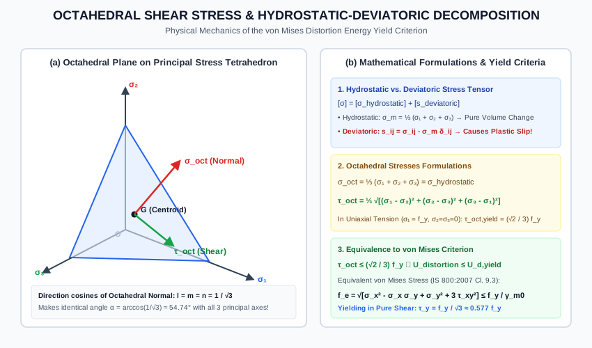
The Octahedral Plane is an oblique plane whose unit normal vector makes equal angles with all three principal axes (n1=n2=n3=1/3n_1 = n_2 = n_3 = 1/\sqrt{3}).

Stresses on the Octahedral Plane:

  1. Octahedral Normal Stress (σoct\sigma_{\text{oct}}): σoct=σ1+σ2+σ33=σhydrostatic(Eq. 5.24)\mathbf{\sigma_{\text{oct}} = \frac{\sigma_1 + \sigma_2 + \sigma_3}{3} = \sigma_{\text{hydrostatic}}} \tag{Eq. 5.24}
  2. Octahedral Shear Stress (τoct\tau_{\text{oct}}): τoct=13(σ1−σ2)2+(σ2−σ3)2+(σ3−σ1)2(Eq. 5.25)\mathbf{\tau_{\text{oct}} = \frac{1}{3}\sqrt{(\sigma_1 - \sigma_2)^2 + (\sigma_2 - \sigma_3)^2 + (\sigma_3 - \sigma_1)^2}} \tag{Eq. 5.25}

In uniaxial tension at yield (σ1=fy,σ2=σ3=0\sigma_1 = f_y, \sigma_2 = \sigma_3 = 0):

τoct, yield=13(fy−0)2+0+(0−fy)2=23fy(Eq. 5.26)\tau_{\text{oct, yield}} = \frac{1}{3}\sqrt{(f_y - 0)^2 + 0 + (0 - f_y)^2} = \frac{\sqrt{2}}{3}f_y \tag{Eq. 5.26}

Equating τoct≤τoct, yield\tau_{\text{oct}} \le \tau_{\text{oct, yield}}:

13(σ1−σ2)2+(σ2−σ3)2+(σ3−σ1)2≤23fy\frac{1}{3}\sqrt{(\sigma_1 - \sigma_2)^2 + (\sigma_2 - \sigma_3)^2 + (\sigma_3 - \sigma_1)^2} \le \frac{\sqrt{2}}{3}f_y

Squaring both sides yields Eq. (5.19) identically!

Theorem of Equivalence:
The Maximum Distortion Energy Theory (von Mises) and the Octahedral Shear Stress Theory are mathematically and physically identical.


3.7 Combined Bending and Torsion under Failure Theories

For a solid circular shaft of diameter dd subjected to bending moment MM and torque TT:

σ=32Mπd3,τ=16Tπd3,Zb=πd332\sigma = \frac{32 M}{\pi d^3}, \quad \tau = \frac{16 T}{\pi d^3}, \quad Z_b = \frac{\pi d^3}{32} Theory of FailureEquivalent FormulationShaft Diameter Relationship (d∝)Rankine (Max Principal Stress)Me=12(M+M2+T2)d=[32Meπσallow]1/3Tresca (Max Shear Stress)Te=M2+T2d=[16Teπτallow]1/3=[32M2+T2πfy/FOS]1/3von Mises (Distortion Energy)Me,vm=M2+34T2d=[32M2+0.75T2πfy/FOS]1/3\begin{array}{|l|l|l|} \hline \textbf{Theory of Failure} & \textbf{Equivalent Formulation} & \textbf{Shaft Diameter Relationship } (d \propto) \\ \hline \text{Rankine (Max Principal Stress)} & M_e = \frac{1}{2}\left(M + \sqrt{M^2 + T^2}\right) & d = \left[\frac{32 M_e}{\pi \sigma_{\text{allow}}}\right]^{1/3} \\ \hline \text{Tresca (Max Shear Stress)} & T_e = \sqrt{M^2 + T^2} & d = \left[\frac{16 T_e}{\pi \tau_{\text{allow}}}\right]^{1/3} = \left[\frac{32 \sqrt{M^2 + T^2}}{\pi f_y / \text{FOS}}\right]^{1/3} \\ \hline \text{von Mises (Distortion Energy)} & M_{e,vm} = \sqrt{M^2 + \frac{3}{4}T^2} & d = \left[\frac{32 \sqrt{M^2 + 0.75 T^2}}{\pi f_y / \text{FOS}}\right]^{1/3} \\ \hline \end{array}

Notice that M2+0.75T2<M2+T2\sqrt{M^2 + 0.75 T^2} < \sqrt{M^2 + T^2}.
Therefore, the von Mises criterion yields a slightly smaller shaft diameter (dvm<dtrescad_{\text{vm}} < d_{\text{tresca}}), saving approximately 5% to 9%5\% \text{ to } 9\% of shaft steel while guaranteeing rigorous safety!


4. Engineering Assumptions & Limitations

  1. Isotropic Yield Behavior: Assumes the material yields symmetrically in tension and compression (fyt=fyc=fyf_{yt} = f_{yc} = f_y). Not applicable to materials with differing tension/compression strengths (e.g., concrete, cast iron, unreinforced masonry), which require Mohr-Coulomb or Drucker-Prager models.
  2. Initial Elastic Limit: These theories govern the initiation of inelastic deformation (yield point), not post-yield strain hardening or ultimate plastic collapse.
  3. Absence of High Triaxial Tensile Hydrostatic Stress: Under extreme hydrostatic tension (σ1=σ2=σ3>0\sigma_1 = \sigma_2 = \sigma_3 > 0), even ductile metals fracture by brittle cleavage before shear slip can develop.
  4. Room Temperature & Quasi-Static Loading: Does not account for high-temperature creep or high-strain-rate impact effects.

5. Technical Diagrams

Diagram 1: Comparative 2D Yield Loci in Plane Stress

The vector diagram below illustrates the superposed failure envelopes of all five classical theories in the normalized (σ1/fy,σ2/fy)(\sigma_1/f_y, \sigma_2/f_y) plane, highlighting the safe domains and pure shear intercepts.

Comparative Failure Envelopes

Diagram 2: Octahedral Shear Stress & Stress Decomposition

The diagram below details the 3D geometry of the octahedral plane, the hydrostatic-deviatoric stress tensor decomposition, and the physical origin of the von Mises yield criterion.

Octahedral Shear Stress Tetrahedron

6. Solved Numerical Examples

Example 5.1: Multi-Theory Evaluation of Factor of Safety

A structural steel bracket (fy=250 MPaf_y = 250\text{ MPa}, ν=0.30\nu = 0.30) is subjected to a state of plane stress where the principal stresses are:

  • σ1=+140 MPa\sigma_1 = +140\text{ MPa} (Tension)
  • σ2=−80 MPa\sigma_2 = -80\text{ MPa} (Compression)
  • σ3=0 MPa\sigma_3 = 0\text{ MPa}

Determine the Factor of Safety (FOS) against yielding according to:

  1. Maximum Principal Stress Theory (Rankine)
  2. Maximum Shear Stress Theory (Tresca)
  3. Maximum Principal Strain Theory (Saint-Venant)
  4. Maximum Total Strain Energy Theory (Haigh)
  5. Maximum Distortion Energy Theory (von Mises)
Given:
fy = 250 MPa
ν = 0.30
σ1 = +140 MPa
σ2 = -80 MPa
σ3 = 0 MPa

Solution:

1. Rankine's Theory (Maximum Principal Stress):

σmax⁡=σ1=140 MPa≤fyFOS\sigma_{\max} = \sigma_1 = 140\text{ MPa} \le \frac{f_y}{\text{FOS}} FOSRankine=fyσ1=250140=1.786\text{FOS}_{\text{Rankine}} = \frac{f_y}{\sigma_1} = \frac{250}{140} = \mathbf{1.786}

2. Tresca's Theory (Maximum Shear Stress): Since σ1>0\sigma_1 > 0 and σ2<0\sigma_2 < 0, the principal stresses have opposite signs.

τabs, max=σ1−σ22=140−(−80)2=2202=110 MPa\tau_{\text{abs, max}} = \frac{\sigma_1 - \sigma_2}{2} = \frac{140 - (-80)}{2} = \frac{220}{2} = 110\text{ MPa} τabs, max≤fy2⋅FOS  ⟹  110≤125FOS\tau_{\text{abs, max}} \le \frac{f_y}{2 \cdot \text{FOS}} \implies 110 \le \frac{125}{\text{FOS}} FOSTresca=125110=250220=1.136\text{FOS}_{\text{Tresca}} = \frac{125}{110} = \frac{250}{220} = \mathbf{1.136}

3. Saint-Venant's Theory (Maximum Principal Strain): The maximum equivalent strain stress is:

σeq=σ1−νσ2=140−0.30(−80)=140+24=164 MPa\sigma_{\text{eq}} = \sigma_1 - \nu \sigma_2 = 140 - 0.30(-80) = 140 + 24 = 164\text{ MPa} FOSSt.Venant=fyσeq=250164=1.524\text{FOS}_{\text{St.Venant}} = \frac{f_y}{\sigma_{\text{eq}}} = \frac{250}{164} = \mathbf{1.524}

4. Haigh's Theory (Total Strain Energy):

σeq=σ12+σ22−2νσ1σ2=1402+(−80)2−2(0.30)(140)(−80)\sigma_{\text{eq}} = \sqrt{\sigma_1^2 + \sigma_2^2 - 2\nu \sigma_1 \sigma_2} = \sqrt{140^2 + (-80)^2 - 2(0.30)(140)(-80)} σeq=19,600+6,400+6,720=32,720≈180.89 MPa\sigma_{\text{eq}} = \sqrt{19,600 + 6,400 + 6,720} = \sqrt{32,720} \approx 180.89\text{ MPa} FOSHaigh=fyσeq=250180.89=1.382\text{FOS}_{\text{Haigh}} = \frac{f_y}{\sigma_{\text{eq}}} = \frac{250}{180.89} = \mathbf{1.382}

5. von Mises' Theory (Distortion Energy):

σv=σ12−σ1σ2+σ22=1402−(140)(−80)+(−80)2\sigma_v = \sqrt{\sigma_1^2 - \sigma_1 \sigma_2 + \sigma_2^2} = \sqrt{140^2 - (140)(-80) + (-80)^2} σv=19,600+11,200+6,400=37,200≈192.87 MPa\sigma_v = \sqrt{19,600 + 11,200 + 6,400} = \sqrt{37,200} \approx 192.87\text{ MPa} FOSvon Mises=fyσv=250192.87=1.296\text{FOS}_{\text{von Mises}} = \frac{f_y}{\sigma_v} = \frac{250}{192.87} = \mathbf{1.296}

Summary Comparison:

Rankine (1.786)>St. Venant (1.524)>Haigh (1.382)>von Mises (1.296)>Tresca (1.136)\text{Rankine (1.786)} > \text{St. Venant (1.524)} > \text{Haigh (1.382)} > \text{von Mises (1.296)} > \text{Tresca (1.136)}

Tresca provides the most conservative safety factor, while Rankine is dangerously unconservative under opposite-sign biaxial stress!


Example 5.2: Shaft Sizing under Combined Bending and Torsion

A solid circular steel drive shaft (fy=300 MPaf_y = 300\text{ MPa}) is subjected to a bending moment M=12 kN⋅mM = 12\text{ kN}\cdot\text{m} and a twisting moment T=16 kN⋅mT = 16\text{ kN}\cdot\text{m}. Using a design factor of safety FOS=2.0\text{FOS} = 2.0 (σallow=150 MPa,τallow=75 MPa\sigma_{\text{allow}} = 150\text{ MPa}, \tau_{\text{allow}} = 75\text{ MPa}): Calculate the required minimum shaft diameter dd using:

  1. Maximum Shear Stress Theory (Tresca)
  2. Maximum Distortion Energy Theory (von Mises)
Given:
M = 12 kNm = 12 × 10^6 N-mm
T = 16 kNm = 16 × 10^6 N-mm
fy = 300 MPa, FOS = 2.0
σ_allow = 150 MPa, τ_allow = 75 MPa

Solution:

1. Sizing by Tresca's Theory: Equivalent twisting moment:

Te=M2+T2=122+162=144+256=400=20 kN⋅m=20×106 N⋅mmT_e = \sqrt{M^2 + T^2} = \sqrt{12^2 + 16^2} = \sqrt{144 + 256} = \sqrt{400} = 20\text{ kN}\cdot\text{m} = 20 \times 10^6\text{ N}\cdot\text{mm}

The maximum shear stress equation is:

τmax⁡=16Teπd3≤τallow=75 MPa\tau_{\max} = \frac{16 T_e}{\pi d^3} \le \tau_{\text{allow}} = 75\text{ MPa} d3≥16(20×106)π(75)=320×106235.619≈1,358,122.2 mm3d^3 \ge \frac{16(20 \times 10^6)}{\pi(75)} = \frac{320 \times 10^6}{235.619} \approx 1,358,122.2\text{ mm}^3 dTresca=(1,358,122.2)1/3=110.74 mm\mathbf{d_{\text{Tresca}} = (1,358,122.2)^{1/3} = 110.74\text{ mm}}

2. Sizing by von Mises' Theory: Equivalent von Mises bending moment:

Me,vm=M2+34T2=122+0.75(162)=144+0.75(256)=144+192=336≈18.3303 kN⋅mM_{e,vm} = \sqrt{M^2 + \frac{3}{4}T^2} = \sqrt{12^2 + 0.75(16^2)} = \sqrt{144 + 0.75(256)} = \sqrt{144 + 192} = \sqrt{336} \approx 18.3303\text{ kN}\cdot\text{m} Me,vm=18.3303×10⁶ N⋅mmM_{e,vm} = 18.3303 \times 10^6\text{ N}\cdot\text{mm}

The equivalent stress equation is:

σv=32Me,vmπd3≤σallow=150 MPa\sigma_v = \frac{32 M_{e,vm}}{\pi d^3} \le \sigma_{\text{allow}} = 150\text{ MPa} d3≥32(18.3303×10⁶)π(150)=586.5696×106471.239≈1,244,739.5 mm3d^3 \ge \frac{32(18.3303 \times 10^6)}{\pi(150)} = \frac{586.5696 \times 10^6}{471.239} \approx 1,244,739.5\text{ mm}^3 dvon Mises=(1,244,739.5)1/3=107.57 mm\mathbf{d_{\text{von Mises}} = (1,244,739.5)^{1/3} = 107.57\text{ mm}}

Engineering Economics Observation:

AvmATresca=(107.57110.74)2=(0.9714)2≈0.9436  ⟹  5.65% steel weight saving\frac{A_{\text{vm}}}{A_{\text{Tresca}}} = \left(\frac{107.57}{110.74}\right)^2 = (0.9714)^2 \approx 0.9436 \implies \mathbf{5.65\%\text{ steel weight saving}}

Using von Mises yields a material savings of 5.65%5.65\% in steel volume while fully satisfying ductile yielding safety.


Example 5.3: Hydrostatic Invariance of Octahedral Shear Stress

A rock core in deep crustal drilling is subjected to the triaxial stress state:

  • σ1=+280 MPa\sigma_1 = +280\text{ MPa}
  • σ2=+200 MPa\sigma_2 = +200\text{ MPa}
  • σ3=+120 MPa\sigma_3 = +120\text{ MPa}

Yield strength in simple tension is fy=240 MPaf_y = 240\text{ MPa}.

  1. Compute the octahedral normal stress σoct\sigma_{\text{oct}} and octahedral shear stress τoct\tau_{\text{oct}}.
  2. Determine if the material yields under the von Mises / Octahedral Shear criterion.
  3. If an additional uniform fluid pressure p=500 MPap = 500\text{ MPa} is superposed onto the core (σi′=σi−500\sigma_i' = \sigma_i - 500), calculate the new σoct′\sigma_{\text{oct}}' and τoct′\tau_{\text{oct}}', and explain the physical significance.
Given:
σ1 = 280 MPa, σ2 = 200 MPa, σ3 = 120 MPa
fy = 240 MPa

Solution:

Step 1: Compute Initial Octahedral Stresses

σoct=σ1+σ2+σ33=280+200+1203=6003=+200 MPa\sigma_{\text{oct}} = \frac{\sigma_1 + \sigma_2 + \sigma_3}{3} = \frac{280 + 200 + 120}{3} = \frac{600}{3} = \mathbf{+200\text{ MPa}} τoct=13(σ1−σ2)2+(σ2−σ3)2+(σ3−σ1)2\tau_{\text{oct}} = \frac{1}{3}\sqrt{(\sigma_1 - \sigma_2)^2 + (\sigma_2 - \sigma_3)^2 + (\sigma_3 - \sigma_1)^2} τoct=13(280−200)2+(200−120)2+(120−280)2=13802+802+(−160)2\tau_{\text{oct}} = \frac{1}{3}\sqrt{(280 - 200)^2 + (200 - 120)^2 + (120 - 280)^2} = \frac{1}{3}\sqrt{80^2 + 80^2 + (-160)^2} τoct=136400+6400+25600=1338400=195.963=65.32 MPa\tau_{\text{oct}} = \frac{1}{3}\sqrt{6400 + 6400 + 25600} = \frac{1}{3}\sqrt{38400} = \frac{195.96}{3} = \mathbf{65.32\text{ MPa}}

Step 2: Check Yield Condition In uniaxial tension at yield (fy=240 MPaf_y = 240\text{ MPa}):

τoct, yield=23fy=23(240)=802≈113.14 MPa\tau_{\text{oct, yield}} = \frac{\sqrt{2}}{3} f_y = \frac{\sqrt{2}}{3}(240) = 80\sqrt{2} \approx \mathbf{113.14\text{ MPa}}

Because τoct=65.32 MPa<113.14 MPa\tau_{\text{oct}} = 65.32\text{ MPa} < 113.14\text{ MPa}, the core does NOT yield.

FOS=113.1465.32=1.732\text{FOS} = \frac{113.14}{65.32} = \mathbf{1.732}

Step 3: Superposed Hydrostatic Pressure (p=500 MPap = 500\text{ MPa}) New principal stresses:

σ1′=280−500=−220 MPa\sigma_1' = 280 - 500 = -220\text{ MPa} σ2′=200−500=−300 MPa\sigma_2' = 200 - 500 = -300\text{ MPa} σ3′=120−500=−380 MPa\sigma_3' = 120 - 500 = -380\text{ MPa}

New octahedral normal stress:

σoct′=−220−300−3803=−9003=−300 MPa\sigma_{\text{oct}}' = \frac{-220 - 300 - 380}{3} = \frac{-900}{3} = \mathbf{-300\text{ MPa}}

New octahedral shear stress:

σ1′−σ2′=−220−(−300)=+80 MPa\sigma_1' - \sigma_2' = -220 - (-300) = +80\text{ MPa} σ2′−σ3′=−300−(−380)=+80 MPa\sigma_2' - \sigma_3' = -300 - (-380) = +80\text{ MPa} σ3′−σ1′=−380−(−220)=−160 MPa\sigma_3' - \sigma_1' = -380 - (-220) = -160\text{ MPa} τoct′=13802+802+(−160)2=65.32 MPa(Identically Unchanged!)\tau_{\text{oct}}' = \frac{1}{3}\sqrt{80^2 + 80^2 + (-160)^2} = \mathbf{65.32\text{ MPa}}\quad (\text{Identically Unchanged!})

Physical Significance:
Superposing uniform hydrostatic pressure shifts the normal stress state along the hydrostatic axis (σoct\sigma_{\text{oct}} changes by −500 MPa-500\text{ MPa}), but has identically zero effect on octahedral shear stress τoct\tau_{\text{oct}}. Hydrostatic pressure causes only volume contraction; it produces no shear distortion and cannot induce plastic yielding in ductile metals.


7. Practical & Field Engineering Applications

  1. Structural Steel Building & Bridge Design (IS 800:2007):
    Under Clause 9.3 of IS 800:2007, structural steel elements subjected to combined bending moments, axial thrust, and torsional shear must satisfy the equivalent von Mises stress limit:

    fe=σx2−σxσy+σy2+3τxy2≤fyγm0f_e = \sqrt{\sigma_x^2 - \sigma_x \sigma_y + \sigma_y^2 + 3\tau_{xy}^2} \le \frac{f_y}{\gamma_{m0}}

    where γm0=1.10\gamma_{m0} = 1.10 is the partial safety factor for material yield.

  2. Shafts in Heavy Machinery & Winch Drives:
    ASME codes and machine design standards mandate Tresca for conservative sizing and von Mises for weight-optimized rotor shafts in power turbines, automotive axles, and sluice gate hoists.

  3. Reinforced Concrete & Plain Masonry (IS 456:2000):
    Plain concrete has compressive strength 10 to 15 times its tensile strength. Rankine's maximum principal stress theory governs diagonal tension cracking in beam webs and punching shear in footings.

  4. Soil & Rock Mechanics Foundations:
    Frictional particulate materials (sands, clays, jointed rocks) increase shear strength under confining pressure. Modified Coulomb-Mohr and Drucker-Prager (an extension of von Mises with hydrostatic dependency) criteria are used.


8. Comparative Analysis

Exhaustive Failure Theories Comparison Matrix

Theory Proposed By Failure Criterion 2D Locus Shape Pure Shear Ratio τy/fy\tau_y / f_y Best Material Application Modern Code Adoption
Max Principal Stress Rankine (1857) σ1≤fy\sigma_1 \le f_y Square 1.0001.000 Brittle (Concrete, Cast Iron, Rock) IS 456, ACI 318
Max Shear Stress Tresca (1864) τmax⁡≤fy2\tau_{\max} \le \frac{f_y}{2} Hexagon 0.5000.500 Ductile (Mild steel, copper) ASME BPVC, Conservative codes
Max Principal Strain St. Venant (1837) σ1−νσ2≤fy\sigma_1 - \nu\sigma_2 \le f_y Rhombus 11+ν≈0.769\frac{1}{1+\nu} \approx 0.769 Obsolete (Historical interest) Abandoned
Max Strain Energy Haigh (1919) σ12+σ22−2νσ1σ2≤fy2\sigma_1^2 + \sigma_2^2 - 2\nu\sigma_1\sigma_2 \le f_y^2 Ellipse 12(1+ν)≈0.620\frac{1}{\sqrt{2(1+\nu)}} \approx 0.620 Moderate ductile under low hydrostatic Seldom used
Distortion Energy von Mises (1913) σ12−σ1σ2+σ22≤fy2\sigma_1^2 - \sigma_1\sigma_2 + \sigma_2^2 \le f_y^2 Ellipse 13≈0.577\frac{1}{\sqrt{3}} \approx \mathbf{0.577} Ductile metals (Structural steel) IS 800, Eurocode 3, AISC

9. Key Engineering Facts & Exam Takeaways

  1. Pure Shear Hierarchy: The theoretical ratio of shear yield strength to tensile yield strength varies widely: Tresca (0.500)<von Mises (0.577)<Haigh (0.620)<St. Venant (0.769)<Rankine (1.000)\text{Tresca (0.500)} < \text{von Mises (0.577)} < \text{Haigh (0.620)} < \text{St. Venant (0.769)} < \text{Rankine (1.000)}
  2. Tresca Hexagon is Inscribed in von Mises Ellipse: The Tresca hexagon touches the von Mises ellipse at 6 boundary points (corresponding to uniaxial tension/compression and equal biaxial states). Everywhere else, Tresca lies strictly inside the ellipse, confirming it is always more conservative.
  3. Identical in Uniaxial Tension: All five theories predict identical yield loads under pure uniaxial tension (σ1=fy,σ2=σ3=0\sigma_1 = f_y, \sigma_2 = \sigma_3 = 0). They only diverge under multiaxial and shear states.
  4. Hydrostatic Stress Independence: In von Mises and Tresca, superposing uniform hydrostatic tension or compression (σm\sigma_m) has identically zero effect on the yield condition.
  5. Factor 3\sqrt{3} in Shear: In von Mises, τy=fy/3\tau_y = f_y / \sqrt{3}. This explains why shear stress carries a multiplier of 33 in the equivalent stress formula: σv=σ2+3τ2\sigma_v = \sqrt{\sigma^2 + 3\tau^2}.

10. Common Pitfalls, Traps & Anti-Patterns

  • Trap 1 (Using In-Plane Shear in Tresca): In a state of biaxial tension with σ1=120 MPa\sigma_1 = 120\text{ MPa} and σ2=80 MPa\sigma_2 = 80\text{ MPa}, reporting τmax⁡=120−802=20 MPa\tau_{\max} = \frac{120 - 80}{2} = 20\text{ MPa}. Since σ3=0\sigma_3 = 0, the true maximum shear is 120−02=60 MPa\frac{120 - 0}{2} = 60\text{ MPa}!
  • Trap 2 (Applying Rankine to Structural Steel): Using maximum principal stress theory for steel beams subjected to heavy shear. Rankine predicts τy=fy\tau_y = f_y, which will cause catastrophic premature yielding at ≈58%\approx 58\% of the expected load!
  • Trap 3 (Confusing Tresca vs von Mises Shear Yield): In exam questions, mixing up τy=0.50fy\tau_y = 0.50 f_y (Tresca) with τy=0.577fy\tau_y = 0.577 f_y (von Mises).
  • Trap 4 (Applying von Mises to Concrete): Using distortion energy for plain concrete. Concrete fails by brittle tensile cracking, not shear dislocation slip; Rankine or Mohr-Coulomb must be used.
  • Trap 5 (Forgetting the 0.750.75 Factor in Shaft Design): For von Mises shaft equivalent moment, writing M2+T2\sqrt{M^2 + T^2} instead of M2+0.75T2\sqrt{M^2 + 0.75 T^2}.

11. Standards & Code Provisions

IS 800:2007 (General Construction in Steel - Code of Practice)

  • Clause 9.3 (Combined Stresses): Mandates that at every critical section of a structural steel member, the equivalent stress calculated by von Mises' criterion must not exceed the design yield strength: σx2−σxσy+σy2+3τxy2≤fyγm0\sqrt{\sigma_x^2 - \sigma_x\sigma_y + \sigma_y^2 + 3\tau_{xy}^2} \le \frac{f_y}{\gamma_{m0}}
  • Table 5: Partial safety factor for resistance governed by yielding: γm0=1.10\gamma_{m0} = 1.10.

IS 456:2000 (Plain and Reinforced Concrete - Code of Practice)

  • Clause 40.1 & Clause 40.2: Diagonal tensile stresses are limited by the design shear strength of concrete τc\tau_c, which is derived from the Rankine tensile cracking threshold (fct=0.7fckf_{ct} = 0.7\sqrt{f_{ck}}).

ASME Boiler and Pressure Vessel Code (Section VIII, Division 2)

  • Recommends the von Mises effective stress for primary membrane and bending stress intensity evaluations in high-pressure reactor vessels.

12. Comprehensive Formula Box & Practice Problems

Master Formula Summary

Theory & CriterionPlane Stress Formulation (σ3=0)Rankine (Max Principal Stress)σ1≤fyFOSTresca (Max Shear Stress)max⁡(∣σ1−σ2∣2,∣σ1∣2,∣σ2∣2)≤fy2⋅FOSSaint-Venant (Max Principal Strain)σ1−νσ2≤fyFOSHaigh (Total Strain Energy)σ12+σ22−2νσ1σ2≤(fyFOS)2von Mises (Distortion Energy)σ12−σ1σ2+σ22≤(fyFOS)2von Mises Cartesian Equivalent Stressσv=σx2−σxσy+σy2+3τxy2≤fyFOSOctahedral Shear Stressτoct=13(σ1−σ2)2+(σ2−σ3)2+(σ3−σ1)2≤23fyFOSPure Shear Yield: Trescaτy=0.500fyPure Shear Yield: von Misesτy=fy3≈0.577fyShaft Equivalent Moment (von Mises)Me,vm=M2+0.75T2\begin{array}{|l|l|} \hline \textbf{Theory \& Criterion} & \textbf{Plane Stress Formulation } (\sigma_3 = 0) \\ \hline \text{Rankine (Max Principal Stress)} & \sigma_1 \le \frac{f_y}{\text{FOS}} \\ \hline \text{Tresca (Max Shear Stress)} & \max\left(\frac{|\sigma_1 - \sigma_2|}{2}, \frac{|\sigma_1|}{2}, \frac{|\sigma_2|}{2}\right) \le \frac{f_y}{2 \cdot \text{FOS}} \\ \hline \text{Saint-Venant (Max Principal Strain)} & \sigma_1 - \nu \sigma_2 \le \frac{f_y}{\text{FOS}} \\ \hline \text{Haigh (Total Strain Energy)} & \sigma_1^2 + \sigma_2^2 - 2\nu \sigma_1 \sigma_2 \le \left(\frac{f_y}{\text{FOS}}\right)^2 \\ \hline \text{von Mises (Distortion Energy)} & \sigma_1^2 - \sigma_1 \sigma_2 + \sigma_2^2 \le \left(\frac{f_y}{\text{FOS}}\right)^2 \\ \hline \text{von Mises Cartesian Equivalent Stress} & \sigma_v = \sqrt{\sigma_x^2 - \sigma_x \sigma_y + \sigma_y^2 + 3\tau_{xy}^2} \le \frac{f_y}{\text{FOS}} \\ \hline \text{Octahedral Shear Stress} & \tau_{\text{oct}} = \frac{1}{3}\sqrt{(\sigma_1 - \sigma_2)^2 + (\sigma_2 - \sigma_3)^2 + (\sigma_3 - \sigma_1)^2} \le \frac{\sqrt{2}}{3}\frac{f_y}{\text{FOS}} \\ \hline \text{Pure Shear Yield: Tresca} & \tau_y = 0.500 f_y \\ \hline \text{Pure Shear Yield: von Mises} & \tau_y = \frac{f_y}{\sqrt{3}} \approx 0.577 f_y \\ \hline \text{Shaft Equivalent Moment (von Mises)} & M_{e,vm} = \sqrt{M^2 + 0.75 T^2} \\ \hline \end{array}

Practice Problems

  1. Problem 1 (GATE CE Objective):
    According to the maximum distortion energy theory of failure, the yield strength in pure shear τy\tau_y is related to the yield strength in simple tension fyf_y by:
    Answer: τy=fy3≈0.577fy\tau_y = \frac{f_y}{\sqrt{3}} \approx 0.577 f_y
    Explanation: In pure shear, σ1=τ,σ2=−τ\sigma_1 = \tau, \sigma_2 = -\tau. Substituting into σ12−σ1σ2+σ22=3τ2=fy2  ⟹  τy=fy/3\sigma_1^2 - \sigma_1\sigma_2 + \sigma_2^2 = 3\tau^2 = f_y^2 \implies \tau_y = f_y / \sqrt{3}.

  2. Problem 2 (SSC JE Objective):
    The failure envelope for the maximum shear stress theory (Tresca) in a 2D state of plane stress is a:
    Answer: Hexagon
    Explanation: The Tresca yield locus in the (σ1,σ2)(\sigma_1, \sigma_2) plane forms a 6-sided polygon (hexagon) bounded by σ1=±fy\sigma_1 = \pm f_y, σ2=±fy\sigma_2 = \pm f_y, and σ1−σ2=±fy\sigma_1 - \sigma_2 = \pm f_y.

  3. Problem 3 (GATE CE Numerical):
    A bolt is subjected to an axial tensile force causing tensile stress σ=120 MPa\sigma = 120\text{ MPa} and a shear force causing shear stress τ=50 MPa\tau = 50\text{ MPa}. If the yield strength of the steel is fy=250 MPaf_y = 250\text{ MPa}, the factor of safety according to von Mises theory is:
    Answer: 1.691.69
    Explanation: σv=σ2+3τ2=1202+3(502)=14400+3(2500)=14400+7500=21900≈147.986 MPa\sigma_v = \sqrt{\sigma^2 + 3\tau^2} = \sqrt{120^2 + 3(50^2)} = \sqrt{14400 + 3(2500)} = \sqrt{14400 + 7500} = \sqrt{21900} \approx 147.986\text{ MPa}.
    FOS=fyσv=250147.986≈1.689≈1.69\text{FOS} = \frac{f_y}{\sigma_v} = \frac{250}{147.986} \approx 1.689 \approx 1.69.

  4. Problem 4 (UPSC ESE Style):
    Which theory of failure is most appropriate for predicting the failure of brittle materials like cast iron and concrete?
    Answer: Maximum Principal Stress Theory (Rankine)
    Explanation: Brittle materials fail primarily by tensile separation across cleavage planes when the major principal stress reaches the ultimate tensile strength.

  5. Problem 5 (State AE Objective):
    In a 3D state of stress where σ1=σ2=σ3=−200 MPa\sigma_1 = \sigma_2 = \sigma_3 = -200\text{ MPa} (hydrostatic compression), the octahedral shear stress is:
    Answer: 0 MPa0\text{ MPa}
    Explanation: τoct=13(σ1−σ2)2+(σ2−σ3)2+(σ3−σ1)2=130+0+0=0 MPa\tau_{\text{oct}} = \frac{1}{3}\sqrt{(\sigma_1 - \sigma_2)^2 + (\sigma_2 - \sigma_3)^2 + (\sigma_3 - \sigma_1)^2} = \frac{1}{3}\sqrt{0 + 0 + 0} = 0\text{ MPa}.