Slenderness Ratio, Critical Stress & Limitations of Euler's Formula
In this chapter (3 topics)
On this page
- 1. Engineering Context & Overview
- 2. Radius of Gyration (r) & The Slenderness Ratio (λ)
- 2.1 Least Radius of Gyration (rmin)
- 2.2 Slenderness Ratio (λ)
- 3. The Euler Buckling Stress Formula & The Euler Hyperbola
- 3.1 Derivation of Critical Buckling Stress (σcr)
- 3.2 The Euler Hyperbola
- 4. Limiting / Critical Slenderness Ratio (λc) & Validity Boundaries
- 4.1 Condition for Validity
- 4.2 Material-Specific Transition Values (λc)
- 5. Cross-Sectional Geometry & Radius of Gyration Formulations
- Why Hollow Sections Are Structurally Superior
- 6. Maximum Permissible Slenderness Ratios per IS 800:2007 (Table 3)
- 7. Engineering Diagrams & Visual Walkthrough
- Figure 1: The Euler Hyperbola & Validity Boundaries
- Figure 2: Radius of Gyration & Cross-Section Buckling Efficiency
- 8. Worked Numerical Examples
- Example 1: Critical Length and Failure Mode of a Square Column
- Example 2: Efficiency Comparison of Sections with Identical Area
- Example 3: Rolled Steel I-Section with Lateral Bracing Design
- 9. Failure Regimes Summary: Short vs Intermediate vs Long Columns
- 10. Common Misconceptions & Exam Pitfalls
- 11. Real-World Engineering Applications & Standard Codes
- 12. Quick Revision Summary & Formula Sheet
1. Engineering Context & Overview
Euler's critical buckling load () establishes the absolute upper boundary of elastic column stability. However, when evaluating compressive stress rather than total load, a fundamental paradox emerges: as column length decreases towards zero (), Euler's formula predicts that the critical buckling stress approaches infinity ().
In physical reality, no engineering material possesses infinite compressive strength. Long before an infinitely large buckling load can develop, the material fibers reach their proportional limit (), yield strength (), or ultimate crushing strength (), causing the column to fail by plastic yielding or crushing.
To define the exact boundary between elastic flexural buckling and material crushing / inelastic failure, structural engineers employ the Slenderness Ratio () and the Radius of Gyration (). Understanding the limiting slenderness ratio (), the Euler hyperbola, and the maximum permissible slenderness limits specified in IS 800:2007 (Table 3) is indispensable for competitive examinations (GATE CE, UPSC ESE, State AE/JE).
2. Radius of Gyration () & The Slenderness Ratio ()
2.1 Least Radius of Gyration ()
The radius of gyration represents the radial distance from the centroidal axis at which the entire cross-sectional area could be concentrated as an infinitesimally thin strip without altering its second moment of area (moment of inertia ):
Since an unbraced column always buckles about the principal axis that offers the least flexural resistance, the critical geometric parameter is the least radius of gyration:
2.2 Slenderness Ratio ()
The slenderness ratio (frequently denoted as or ) is a pure dimensionless geometric index that quantifies the vulnerability of a compression member to lateral flexural buckling:
where:
- = Effective length of the column depending on support end fixity ().
- = Least radius of gyration of the cross-section.
   Physical Meaning of Slenderness Ratio (λ):

   Low λ (< 32)            Intermediate λ (32 - 120)       High λ (> 120)
   ┌─────────┐             ┌───┐                           │
   │         │             │   │                           │
   │  STUBBY │             │   │                           │  SLENDER
   │  COLUMN │             │   │                           │  COLUMN
   │         │             │   │                           │
   └─────────┘             └───┘                           │
   Fails by Crushing       Inelastic Buckling              Pure Elastic Buckling
   (σ_fail = σ_y)          (Rankine / Perry-Robertson)     (Euler: σ_cr = π²E/λ²)
3. The Euler Buckling Stress Formula & The Euler Hyperbola
3.1 Derivation of Critical Buckling Stress ()
Starting from Euler's critical load formula:
Dividing both sides by the total cross-sectional area :
Substitute :
3.2 The Euler Hyperbola
Plotting on the vertical axis against on the horizontal axis yields a curve known as the Euler Hyperbola:
- Critical stress is strictly inversely proportional to the square of the slenderness ratio ().
- The curve is asymptotic to both the vertical stress axis () and the horizontal slenderness axis ().
- Critical buckling stress is independent of the material yield strength ( or ); it depends solely on the elastic stiffness () and geometry (). A high-strength steel (Fe 540) has the identical Euler buckling stress as mild steel (Fe 250) because both have .
4. Limiting / Critical Slenderness Ratio () & Validity Boundaries
4.1 Condition for Validity
Euler's derivation explicitly assumes that the column material remains strictly within the linear elastic regime (Hooke's Law holds). Therefore, Euler's formula is valid if and only if the calculated critical stress does not exceed the proportional limit () or yield stress () of the material:
Solving for the slenderness ratio:
The threshold is called the Limiting (or Critical) Slenderness Ratio.
4.2 Material-Specific Transition Values ()
-
Mild Steel (Structural Fe 250):
, :(If proportional limit is taken: )
-
High-Strength Structural Steel (Fe 410):
, : -
Grey Cast Iron:
, Compressive Crushing Strength : -
Structural Aluminum Alloy (6061-T6):
, : -
Structural Timber (Sal / Teak):
, Compressive Strength parallel to grain :
Exam Summary Rule:
- If (for steel, ): Column is LONG. Failure is by pure elastic buckling. Euler's formula is VALID.
- If (for steel, ): Column is SHORT or INTERMEDIATE. Failure is governed by crushing or inelastic buckling. Euler's formula is INVALID (predicts dangerously unsafe fictitious capacities).
5. Cross-Sectional Geometry & Radius of Gyration Formulations
The least radius of gyration is a function of section shape. The table below compiles analytical expressions for standard cross-sections:
| Section Geometry | Dimensions | Area () | Moment of Inertia () | Radius of Gyration () |
|---|---|---|---|---|
| Solid Circular | Diameter | |||
| Hollow Circular Tube | Outer , Inner | |||
| Thin Circular Ring | Mean Dia , thickness | |||
| Solid Square | Side | |||
| Solid Rectangle | Width , Depth () | |||
| Thin Square Tube | Outer side , thickness | |||
| Equilateral Triangle | Side |
Why Hollow Sections Are Structurally Superior
For an identical cross-sectional area (and thus equal material tonnage):
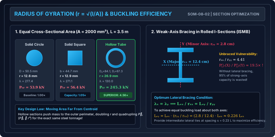
- A solid circular section has .
- A hollow tube with has . Because , the radius of gyration is more than larger, resulting in a critical buckling capacity higher without adding a single gram of steel!
6. Maximum Permissible Slenderness Ratios per IS 800:2007 (Table 3)
In practical structural design, compression members must not be overly slender even if calculated loads are small, because handling, transportation, erection stresses, and unintended vibrations can trigger premature failure. IS 800:2007 Table 3 mandates strict maximum slenderness limits ():
| Type of Member / Loading Condition | Maximum Permissible Slenderness Ratio () |
|---|---|
| 1. Member carrying compressive loads resulting from dead loads and superimposed (live) loads | |
| 2. Member carrying compressive loads resulting from wind or earthquake forces, provided deformation does not adversely affect stress in any part of structure | |
| 3. Member normally acting as a tie in a roof truss or bracing system, subject to possible reversal of stress resulting from wind or earthquake action | |
| 4. Member always in tension (other than pre-tensioned ties) | |
| 5. Lacing bars in built-up columns |
7. Engineering Diagrams & Visual Walkthrough
Figure 1: The Euler Hyperbola & Validity Boundaries
The following diagram demonstrates the decay of critical buckling stress as a function of slenderness ratio , marking the transition point for mild steel, the invalid crushing zone, and the valid elastic buckling regime.
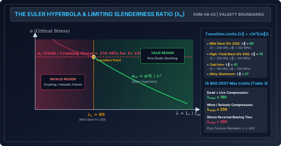
Figure 2: Radius of Gyration & Cross-Section Buckling Efficiency
The following diagram compares the buckling resistance of solid circle, solid square, and thin-walled hollow tube sections of identical cross-sectional area, illustrating why hollow profiles maximize and buckling resistance.
8. Worked Numerical Examples
Example 1: Critical Length and Failure Mode of a Square Column
Problem Statement: A solid square steel column of side is made of mild steel with modulus of elasticity and yield strength .
- Calculate the least radius of gyration of the cross-section.
- Determine the critical/limiting slenderness ratio for this steel.
- Determine the minimum physical length for which Euler's buckling formula is valid when:
- (a) Both ends are hinged ().
- (b) Both ends are fixed ().
- (c) One end is fixed, other free ().
- If the column has a physical length and is hinged at both ends, determine whether it fails by crushing or buckling, and calculate the true failure load.
Solution:
Step 1: Least Radius of Gyration ():
Step 2: Limiting Slenderness Ratio ():
Euler's formula is valid only when .
Step 3: Minimum Physical Length (): Since .
- (a) Both ends hinged ():
- (b) Both ends fixed ():
- (c) One fixed, other free ():
Step 4: Evaluation for (Both ends hinged):
- Effective length: .
- Slenderness ratio:
- Since , the column falls in the inelastic / crushing regime. Euler's formula is completely invalid.
- If one blindly applies Euler's formula:
- True Failure Load: The column yields / crushes at : (Blind reliance on Euler would overestimate capacity by , causing immediate structural collapse!)
Example 2: Efficiency Comparison of Sections with Identical Area
Problem Statement: A pinned-pinned column of length is fabricated from a structural alloy (, yield strength ). The cross-sectional area is constrained to .
Calculate the radius of gyration, slenderness ratio, critical buckling stress , and critical load for:
- A solid circular section.
- A solid square section.
- A hollow circular tube having an inner diameter .
Verify whether each section satisfies Euler's validity criterion ().
Solution:
Step 1: Limiting Slenderness Ratio:
1. Solid Circular Section:
2. Solid Square Section:
3. Hollow Circular Tube ():
Comparative Ratio:
The hollow tube carries of the solid circle's load with identical material consumption.
Example 3: Rolled Steel I-Section with Lateral Bracing Design
Problem Statement: An ISMB 300 column of height is pinned at its top and bottom for buckling about both axes (). To prevent premature buckling about its weak axis (), intermediate lateral bracing is provided at mid-height, fixing .
Given properties of ISMB 300:
- Cross-sectional Area
- Radius of gyration
- Radius of gyration
- Modulus of Elasticity
- Calculate the slenderness ratios and .
- Determine which axis governs buckling and calculate the critical Euler load .
- Determine the optimal spacing of intermediate lateral supports such that the column has equal buckling resistance about both axes.
Solution:
Step 1: Slenderness Ratios:
- About major axis ():
- About minor axis ():
Step 2: Governing Buckling Axis & Critical Load: The larger slenderness ratio yields the lower critical load. Since , buckling occurs about the minor axis:
(Note: About the major axis, )
Step 3: Optimal Lateral Bracing Spacing: For maximum efficiency, the column should buckle simultaneously about both axes:
Design Recommendation: By providing lateral bracing at intervals of (e.g., 4 equal panels of or 5 panels of ), the column's load-carrying capacity is elevated from all the way to the strong-axis capacity of —a strength increase with zero added column weight.
9. Failure Regimes Summary: Short vs Intermediate vs Long Columns
| Column Classification | Slenderness Range (Mild Steel) | Governing Failure Mode | Applicable Theory / Formula |
|---|---|---|---|
| Short Column (Pedestal) | () | Pure Material Crushing (Direct Yielding) | |
| Intermediate Column | Inelastic Buckling + Material Yielding | Rankine-Gordon Formula, Perry-Robertson, Tangent Modulus () | |
| Long (Slender) Column | () | Pure Elastic Buckling (Instability) | Euler's Formula: |
10. Common Misconceptions & Exam Pitfalls
[!WARNING] Pitfall 1: Assuming High-Strength Steel Increases Euler Buckling Load Euler's critical load depends on elastic modulus and geometry (). It has zero dependence on yield strength . Upgrading from Fe 250 to Fe 540 will not increase the buckling load of a slender column ().
[!CAUTION] Pitfall 2: Using Strong-Axis Radius of Gyration () A column always buckles in the weakest direction unless laterally restrained. Always compute using .
[!NOTE] Pitfall 3: Calculating with the Wrong Units Ensure consistent units when computing . If is in (), it must be converted to () before dividing by in ().
11. Real-World Engineering Applications & Standard Codes
- Building Column Design in IS 800:2007 (Section 7):
- Structural steel columns are classified into 4 buckling curves () based on cross-section geometry, flange thickness, and residual stresses.
- Design compressive strength , where .
- Reinforced Concrete Columns in IS 456:2000 (Clause 25.1.2):
- A compression member is classed as "short" when both slenderness ratios and are less than 12. If either exceeds 12, it is designed as a slender column with additional second-order moments ( effects).
- Transmission Towers and Trusses:
- Slender angle sections used as tower diagonals must have their effective length adjusted for bolt end fixity (IS 802 Part 1).
12. Quick Revision Summary & Formula Sheet
| Physical Quantity / Parameter | Analytical Formula / Expression | Standard Value (Mild Steel) |
|---|---|---|
| Least Radius of Gyration | Units: or | |
| Slenderness Ratio | Dimensionless | |
| Critical Euler Buckling Stress | or | |
| Limiting Slenderness Ratio | (Fe 250), (Fe 410) | |
| Minimum Length for Euler Validity | Units: | |
| Solid Circle Radius of Gyration | ||
| Hollow Tube Radius of Gyration | (for ) | |
| Solid Rectangle Radius of Gyration | Where | |
| IS 800 Max Slenderness (DL + LL) | Table 3, Item 1 | |
| IS 800 Max Slenderness (Wind/Quake) | Table 3, Item 2 | |
| Equal Slenderness Bracing Rule | Maximizes column efficiency |