Chapter 05: Shear Stresses in Beams (05_shear_stresses)
Subject
Strength of Materials (Solid Mechanics)
Target Examinations
GATE CE, UPSC ESE, SSC JE, State AE, RRB JE
Prerequisites
SOM-04-01 (Pure Bending Theory & Flexure Formula), SOM-04-02 (Section Modulus & Area Moments of Inertia), SOM-05-01 (Transverse Shear Stress Formula & Shear Flow)
Authoritative Reference Codes
IS 800:2007 (General Construction in Steel — Code of Practice), IS 456:2000 (Plain and Reinforced Concrete), IS 3629:1986 (Structural Timber in Building)
When a beam of arbitrary cross-section is subjected to a vertical transverse shear force V, the horizontal and vertical shear stress τ(y) at any distance y from the neutral axis (NA) is governed by the Jourawski transverse shear formula:
τ(y)=I⋅b(y)V⋅Q(y)
Where:
V is the transverse shear force at the cross-section [N].
I is the second moment of area of the entire cross-section about the neutral axis [mm4].
Q(y)=∫yytopηdA=A′yˉ′ is the first moment of area of the portion of the cross-section above level y about the neutral axis [mm3].
b(y) is the actual cut width of the cross-section measured parallel to the neutral axis at level y[mm].
The Interplay Between Q(y) and b(y)
The spatial profile of τ(y) across the depth of a beam is dictated entirely by the geometric ratio:
b(y)Q(y)
Monotonically Increasing Q(y) Towards the Neutral Axis:
At the outermost fibers (y=ytop or y=ybottom), the cut area A′=0, so Q=0, requiring τ=0. As y→0 (approaching the neutral axis), Q(y) increases monotonically and reaches its absolute mathematical maximum at the neutral axis (Qmax=QNA).
Constant Width Sections (b(y)=constant):
For cross-sections where the cut width b is invariant with depth (such as rectangles), τ(y) is directly proportional to Q(y). Therefore, the maximum shear stress τmaxmust coincide exactly with the neutral axis, following a parabolic curve.
Variable Width Sections (b(y)=constant):
When b(y) varies along the depth (such as circles, triangles, diamonds, and T-sections), the denominator b(y) modulates the curve. If the width b(y) shrinks rapidly towards an apex or narrow zone, the ratio Q(y)/b(y) can peak at a level different from the neutral axis. This gives rise to the classic "non-central shear stress paradox" in triangular and diamond sections.
Sudden Width Discontinuities (I-Sections, T-Sections):
Where the width changes abruptly by an order of magnitude (from flange width B to web thickness tw), Q(y) remains continuous, producing a dramatic, instantaneous step jump in shear stress by the ratio B/tw.
3. Mathematical Derivations for Canonical Cross-Sections
Boundary Values: At top and bottom fibers (y=±d/2), τ(±d/2)=0.
Maximum Value: At the neutral axis (y=0):
τmax=τNA=23τavg=1.50⋅τavg
Shear Carry by Middle Depth: The middle half of the depth (−d/4≤y≤d/4) carries:
Vmid-half=∫−d/4d/4τ(y)bdy=2∫0d/42d3V(1−d24y2)dy=d3V[4d−3d24(d/4)3]=d3V[4d−48d]=1611V=68.75%V
3.2 Solid Circular Cross-Section (Diameter D=2R)
Consider a circular beam of radius R. The centroid and neutral axis coincide with the geometric center (y=0).
The area moment of inertia is:
I=4πR4=64πD4
At a distance y from the neutral axis, the width of the chord is:
b(y)=2R2−y2
To find Q(y), consider a horizontal strip of width b(η)=2R2−η2 and thickness dη located at distance η:
At the neutral axis (y=0), the upper semicircle is cut across two wall thicknesses (bcut=2t).
The first moment of area of the upper semicircle:
QNA=Asemi⋅yˉsemi=(πRmt)⋅(π2Rm)=2Rm2t
Substituting into Jourawski's formula:
τmax=I⋅bV⋅QNA=(πRm3t)⋅(2t)V⋅(2Rm2t)=πRmtV
Comparing with τavg=AV=2πRmtV:
τmax=2.00⋅τavg
Key Characteristics:
The maximum shear stress in a thin-walled circular tube is twice the average shear stress (τmax/τavg=2.0).
This is significantly higher than a solid circular section (1.333) or solid rectangle (1.50) because the material is concentrated far from the NA, and the cut width at the NA is only 2t.
3.4 Symmetrical I-Beam (Flanges B×tf, Web tw×dw, Overall Depth D)
Consider an I-section with overall depth D, flange width B, flange thickness tf, web thickness tw, and web depth dw=D−2tf.
         |<--------- B --------->|
      +--+-----------------------+--+  ^
      |           Flange            |  | tf
      +--+---------+---+---------+--+  v
                   |   |               ^
                   |   |               |
         - - - - - | - |- - - - - - -  | dw   D
              N    |   |    A          |
                   |   | tw            v
      +--+---------+---+---------+--+  ^
      |           Flange            |  | tf
      +--+-----------------------+--+  v
The total moment of inertia about the neutral axis:
Ixx=12BD3−12(B−tw)dw3
Step 1: In the Flange (dw/2≤y≤D/2)
At level y, the cut width is b(y)=B.
The area above y is A′=B(D/2−y), with centroid yˉ′=21(D/2+y).
Because B/tw typically ranges from 10 to 25 in rolled steel sections (e.g., ISMB, ISMC), the shear stress exhibits an abrupt step jump by a factor of 10 to 25!
Step 3: Maximum Shear Stress at Neutral Axis (y=0)
At the neutral axis, the cut includes the flange plus half the web:
The flanges carry less than 2% to 15% of the vertical shear force. This fundamental insight justifies the standard structural engineering design rule: The web is designed to resist 100% of the vertical shear force.
3.5 T-Section (Flange B×tf, Web tw×dw)
In a T-section:
The neutral axis does not lie at mid-depth; its position yˉ must first be computed from the top flange:
yˉ=Btf+twdwBtf(tf/2)+twdw(tf+dw/2)
If the neutral axis falls in the web (the common case), the maximum shear stress occurs at the neutral axis in the web:
τmax=IxxtwVQNA
At the flange-web junction, there is a step jump:
τflangeτweb=twB
At the top of the flange (y=yˉ) and bottom of the stem (y=D−yˉ), τ=0.
4. The Non-Central Peak Shear Stress Paradoxes
4.1 Triangular Cross-Section (Base b, Height h, Apex at Top)
Consider a triangular beam cross-section with base b and height h, with its apex pointing upwards.
[!NOTE]
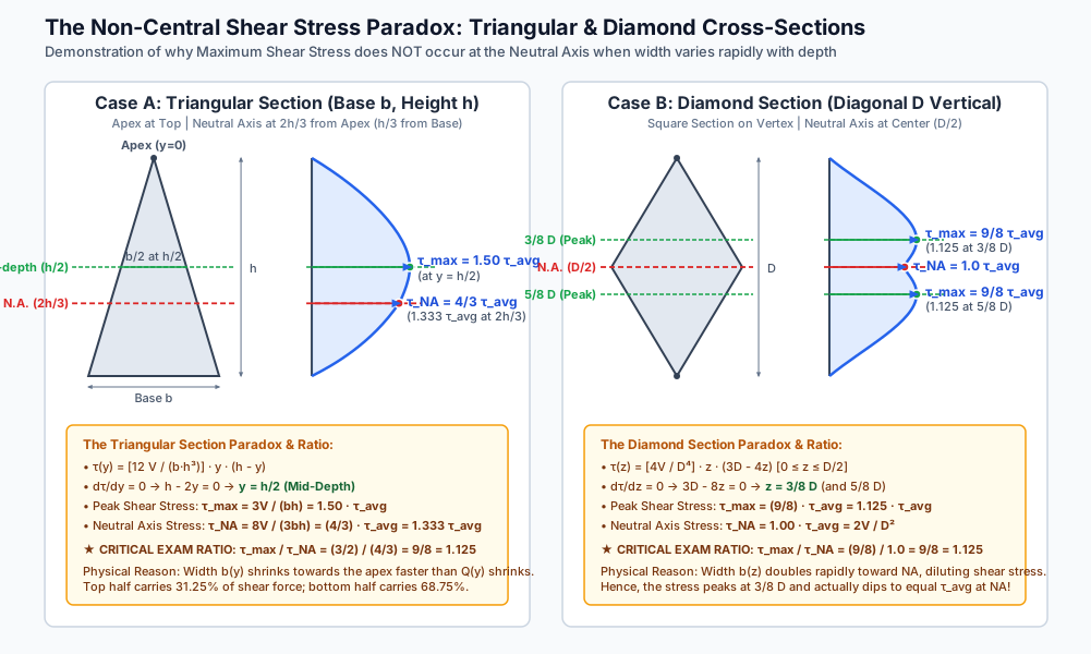
In a diamond section, the shear stress distribution exhibits a twin-peak profile with peaks at 3/8D from top and bottom vertices. At the neutral axis, the stress actually dips to a local minimum equal to the average shear stress (τNA=τavg).
Free Traction-Free Boundary Condition:
At any exposed horizontal surface not subjected to external applied shear traction, the vertical shear stress must vanish:
τ(ytop)=0,τ(ybottom)=0
This is mathematically guaranteed by Q(yext)=0.
Uniform Shear Stress Across Width b:
Jourawski's formula assumes τ is uniform along the horizontal cut line. This is an excellent engineering approximation for slender beams where width b is small relative to depth d (b≪d). For very wide flanges (b>2d), shear lag causes higher shear stresses near the web junction than at outer tips.
Linear Elastic, Homogeneous & Isotropic Material:
Hooke's law applies, and cross-sections remain free from local plate buckling.
Prismatic Axis & Unchecked Torsion:
The transverse shear load V is assumed to pass directly through the shear center of the section. If V does not pass through the shear center, torsional shearing stresses are superposed onto transverse flexural shearing stresses (detailed in SOM-05-03).
6. SVG Technical Illustrations
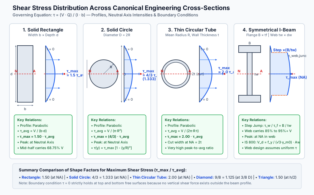
Figure 1: Shear Stress Distribution Profiles in Canonical Sections
The diagram below compares the geometry, neutral axis location, and shear stress profiles for Solid Rectangular, Solid Circular, Thin Circular Tube, and Symmetrical I-Beam cross-sections.
The diagram below provides a detailed side-by-side derivation analysis of why triangular and diamond cross-sections exhibit peak shear stresses away from the neutral axis.
7. Python-Recalculated Solved Numerical Examples
Numerical Example 1: Solid Circular Section vs. Thin-Walled Circular Tube
Problem Statement:
A simply supported beam carries a transverse shear force V=50 kN.
Evaluate and compare the shear stress performance of:
A solid circular cross-section of diameter D=150 mm.
A hollow thin-walled circular tube of outer diameter Do=150 mm and wall thickness t=5 mm.
Specifically determine for both sections:
Cross-sectional area A and average shear stress τavg.
Maximum shear stress τmax and its ratio τmax/τavg.
Shear stress in the solid bar at a distance y=50 mm from the neutral axis.
The material savings achieved by the tube and the corresponding penalty in peak shear stress.
The tube saves 87.11% of steel weight while peak shear stress increases from 3.77 MPa to 43.87 MPa (which remains well within allowable steel shear limits of 100 MPa).
Numerical Example 2: Shear Mechanics of a Triangular Beam
Problem Statement:
An inverted triangular timber beam has base b=180 mm and height h=300 mm. The beam carries a vertical shear force V=36 kN at a critical support.
Calculate:
The average shear stress τavg.
The maximum shear stress τmax and the distance from the apex where it occurs.
The shear stress at the neutral axis τNA.
The shear stress at y=100 mm from apex and at y=250 mm from apex.
The total shear force carried by the upper half of the triangle (from apex y=0 to y=150 mm) and by the lower half.
At y=100 mm:
τ(100)=(8.8889×10−5)×100×(300−100)=8.8889×10−5×20,000=1.7778 MPa(Note: τ(100)=τ(200)=τNA because y(h−y)=100×200=200×100, demonstrating parabolic symmetry about mid-depth y=150 mm!)
At y=250 mm:
τ(250)=(8.8889×10−5)×250×(300−250)=8.8889×10−5×12,500=1.1111 MPa
Shear Force Division Across Upper and Lower Halves:
Upper half (apex to y=150 mm):
Vupper=165V=165×36,000=11,250 N=11.25 kN(31.25%)
Lower half (y=150 mm to y=300 mm):
Vlower=1611V=1611×36,000=24,750 N=24.75 kN(68.75%)
Numerical Example 3: Symmetrical Steel I-Beam (ISMB 350)
Problem Statement:
A rolled steel I-beam ISMB 350 has the following cross-sectional dimensions:
Overall depth D=350 mm
Flange width B=140 mm
Flange thickness tf=14.2 mm
Web thickness tw=8.1 mm
Depth of web between flanges dw=D−2tf=350−28.4=321.6 mm
Total second moment of area Ixx=134.604×106 mm4
The beam is subjected to a vertical shear force V=120 kN.
Calculate:
The shear stress in the flange at the junction with the web.
The shear stress in the web immediately below the junction, and verify the step-jump ratio.
The maximum shear stress at the neutral axis.
The exact vertical shear force carried by the web alone, and the percentage of total shear it represents.
The average web shear stress according to IS 800:2007 (τcode=V/[D⋅tw]), and compare it with the exact peak shear stress at the NA.
Step-by-Step Solution:
Shear Stress in Flange at the Junction (y=dw/2=160.8 mm):
The area of one flange above the junction:
Af=B⋅tf=140×14.2=1,988 mm2
Distance from neutral axis to centroid of flange:
yˉf=2D−tf=2350−14.2=167.9 mm
First moment of area of the flange:
Qf=Afyˉf=1,988×167.9=333,785.20 mm3
At the junction within the flange, the cut width is b=B=140 mm:
Shear Stress in Web at the Junction (y=160.8 mm):
Immediately inside the web, Q remains Qf=333,785.20 mm3, but the cut width contracts to b=tw=8.1 mm:
Structural Steel Plate Girders & I-Sections (IS 800:2007):
Because the web carries over 95% of the vertical shear, deep plate girder webs are made as thin as possible to save weight. However, when the web slenderness ratio dw/tw>67ϵ, the web becomes vulnerable to shear buckling before shear yielding. Vertical intermediate stiffeners are then welded along the web to prevent buckling.
Timber Beams Parallel-to-Grain Shear (IS 3629:1986):
Wood fibers run longitudinally along the beam length. Timber has very low shear strength parallel to the grain (τallow≈0.8 to 1.5 MPa) compared to its bending tensile strength (σallow≈10 to 15 MPa). Consequently, short, heavily loaded timber beams almost invariably fail by horizontal shear splitting along the neutral axis, where τmax=1.5τavg.
Reinforced Concrete Beams (IS 456:2000 Cl. 40):
Concrete has weak tensile capacity. Because Mohr's circle dictates that pure shear on the neutral axis generates principal tensile stresses of magnitude σ1=τ inclined at 45∘, shear failure manifests as diagonal tension cracks starting near the support at the neutral axis. Shear stirrups (vertical or inclined) are provided to intercept these 45∘ diagonal tension cracks.
Prestressed Concrete (P/A Pre-Compression Benefit):
By applying an axial pre-compression σ0=P/A, Mohr's circle is shifted to the right, dramatically reducing the principal tensile stress σ1=(σ0/2)2+τ2−(σ0/2), thereby preventing diagonal shear cracking.
9. Comparative Analysis & Summary Matrix
Section Geometry
Depth Dimension
Neutral Axis Location (yNA)
Second Moment of Area (I)
First Moment at NA (QNA)
Cut Width at NA (bNA)
Location of Peak Shear Stress
Max Shear Stress Ratio (τmax/τavg)
NA Shear Stress Ratio (τNA/τavg)
Peak-to-NA Ratio (τmax/τNA)
Solid Rectangle
Depth d, Width b
d/2 (Mid-depth)
12bd3
8bd2
b
Neutral Axis (y=0)
1.50 (3/2)
1.50 (3/2)
1.000
Solid Circle
Diameter D=2R
R (Center)
4πR4
32R3
2R=D
Neutral Axis (y=0)
1.333 (4/3)
1.333 (4/3)
1.000
Thin Tube
Mean Rad Rm, Thk t
Rm (Center)
πRm3t
2Rm2t
2t
Neutral Axis (y=0)
2.000 (2/1)
2.000 (2/1)
1.000
Triangular (Apex Up)
Base b, Height h
2h/3 from apex (h/3 from base)
36bh3
3hbh294h2=814bh2
32b
Mid-depth (h/2 from apex)
1.500 (3/2)
1.333 (4/3)
1.125 (9/8)
Diamond (Square on Vertex)
Diagonal D vertical
D/2 from vertex
48D4
16D3
D
3/8D & 5/8D from vertices
1.125 (9/8)
1.000 (1/1)
1.125 (9/8)
Symmetrical I-Beam
Flange B, Web tw, Depth D
D/2 (Center)
12BD3−(B−tw)dw3
Btf2D−tf+8twdw2
tw
Neutral Axis (y=0)
ItwτavgVQNA
ItwτavgVQNA
1.000
10. Key Takeaways & Exam-Oriented Highlights
Parabolic Profiles: In rectangular, circular, tubular, triangular, and diamond sections, the shear stress distribution follows a parabolic curve across depth.
Boundary Zero Condition: At free top and bottom boundaries, τ=0 because there is no area above or below the cut (Q=0).
Rectangular Section Rule:τmax=1.50τavg, occurring at the neutral axis. The middle half of a rectangular beam carries 68.75% (1611) of the total vertical shear.
Circular Section Rule:τmax=34τavg≈1.333τavg, occurring at the neutral axis.
Thin Circular Tube Rule:τmax=2.00τavg at the neutral axis.
Triangular Section Paradox:
Maximum shear stress occurs at mid-depth h/2, NOT at the neutral axis (2h/3).
τmax=1.50τavg (at h/2).
τNA=34τavg (at 2h/3).
Critical Ratio: τNAτmax=89=1.125.
Upper half carries 31.25% (5/16), lower half carries 68.75% (11/16) of total shear force.
Diamond Section Paradox:
Maximum shear stress occurs at 3/8D and 5/8D from vertices (81D from NA).
τmax=89τavg=1.125τavg.
At the neutral axis, τNA=1.00τavg.
Critical Ratio: τNAτmax=89=1.125.
I-Section Step Discontinuity: At the flange-web junction, τ jumps abruptly by the factor B/tw. The web carries 85% to 98% of the total vertical shear force.
11. Common Traps, Pitfalls & Counter-Intuitive Exam Scenarios
Trap 1: Assuming τmax Always Occurs at the Neutral Axis: Misconception: Students instinctively answer that maximum shear stress occurs at the neutral axis for all beams. Correction: While true for symmetric sections with non-diminishing width (rectangles, circles, I-beams), it is false for triangles (peaks at h/2) and diamonds (peaks at 3/8D and 5/8D).
Trap 2: Forgetting the Cut Width in Hollow Tubes: Misconception: Calculating shear stress at the NA of a tube using cut width b=t. Correction: A horizontal plane through the neutral axis slices through both walls of the tube, so b=2t. Omitting the factor of 2 doubles the calculated stress incorrectly.
Trap 3: Confusing τmax/τavg with τmax/τNA: Misconception: In competitive exam questions, students confuse the ratio with respect to average stress and the ratio with respect to neutral axis stress. Correction: For a triangle: τmax/τavg=1.50, whereas τmax/τNA=9/8=1.125. Always re-read the denominator requested in the question prompt.
Trap 4: Neglecting Flange Shear Force in Rolled Steel Sections: Misconception: Believing flanges carry no shear at all. Correction: Flanges carry vertical shear (typically 2% to 8%) and also carry significant horizontal transverse shear flows (q=VQ/I) which run from outer tips toward the web junction.
Trap 5: Using Section Depth Rather than Centroid Distance for Q: Misconception: Using the distance to the outer fiber instead of the centroid yˉ′ of the cut area. Correction:Q=A′yˉ′, where yˉ′ is measured from the neutral axis of the full section to the centroid of the isolated area A′.
12. Standard Code Provisions & Objective Practice Problems
Reference Code Clauses
IS 800:2007 (Cl. 8.4): Design shear strength of steel members Vd=Vn/γm0, where Vn=Vp=3Avfy. For rolled I-sections, shear area Av=D⋅tw.
IS 800:2007 (Cl. 8.4.2): Shear buckling resistance must be verified when dw/tw>67ϵ, where ϵ=250/fy.
IS 456:2000 (Cl. 40.1): Nominal shear stress in RCC beams τv=bdVu, with maximum design shear stress limited to τc,max per Table 20.
IS 3629:1986 (Cl. 6.3): Horizontal shear stress in timber beams must satisfy τ=2bd3V≤τallow, parallel.
Objective Practice Problems
Problem 1 (GATE CE / ESE)
In a beam of triangular cross-section of base b and height h, subjected to vertical shear force V, the maximum shear stress occurs at:
The ratio of maximum shear stress to average shear stress in a solid circular beam cross-section is:
(A) 1.50
(B) 1.33
(C) 1.125
(D) 2.00
Answer:(B) Solution: For a solid circle, τmax=34τavg≈1.333.
Problem 3 (GATE CE / State AE)
For a square beam cross-section of side a with its diagonal positioned vertically, the ratio of maximum shear stress to the shear stress at the neutral axis is:
(A) 1.00
(B) 1.125
(C) 1.333
(D) 1.500
Answer:(B) Solution: For a diamond section (square on vertex), τmax=89τavg occurring at 3/8D from vertex, while τNA=1.00τavg at the neutral axis. Hence, τNAτmax=1.09/8=89=1.125.
Problem 4 (ESE / State AE)
In a rectangular beam of width b and depth d carrying vertical shear force V, what percentage of the total shear force is resisted by the middle half of the section (between y=−d/4 and y=+d/4)?
A thin-walled circular tube of mean radius R and wall thickness t (t≪R) is subjected to shear force V. If τavg=V/(2πRt), the maximum shear stress in the tube is:
(A) 34τavg
(B) 1.50τavg
(C) 2.00τavg
(D) 2πτavg
Answer:(C) Solution: At the neutral axis, QNA=2R2t, I=πR3t, and cut width b=2t. Thus, τmax=(πR3t)(2t)V(2R2t)=πRtV=2⋅2πRtV=2.00τavg.