Euler's Theory of Buckling & Critical Loads for Ideal Columns
In this chapter (3 topics)
On this page
- 1. Engineering Context & Overview
- 2. Stability Concepts & Classification of Compression Members
- 2.1 Column vs Strut
- 2.2 Classification by Geometry & Slenderness Ratio (λ)
- 2.3 Mechanical States of Equilibrium
- 3. Assumptions and Limitations of Euler's Theory
- 4. Mathematical Derivation of Euler's Formula
- 4.1 Governing Differential Equation (Case: Both Ends Hinged)
- 4.2 General Solution & Boundary Conditions
- 4.3 Fundamental Critical Load (n = 1)
- 5. Four Standard End Conditions & Effective Lengths
- 5.1 Case 1: Both Ends Hinged / Pinned (Base Reference)
- 5.2 Case 2: Both Ends Fixed
- 5.3 Case 3: One End Fixed, Other End Hinged
- 5.4 Case 4: One End Fixed, Other End Free (Cantilever Column)
- 6. Design vs Theoretical Effective Lengths (IS Codes)
- 7. Engineering Diagrams & Visual Walkthrough
- Figure 1: Euler's Column Buckling Modes & Effective Lengths
- Figure 2: Column Stability States & Pitchfork Bifurcation
- 8. Worked Numerical Examples
- Example 1: Tubular Steel Column Under All Four End Conditions
- Example 2: Built-Up Laced Column with Equal Buckling Strength
- Example 3: Error Analysis of Fixed-Pinned Transcendental Approximation
- 9. Comparative Analysis: Minimum Moment of Inertia Principle
- Rectangular Section Comparison
- Bracing in the Weak Direction
- 10. Common Misconceptions & Exam Pitfalls
- 11. Real-World Engineering Applications & Standard Codes
- 12. Quick Revision Summary & Formula Sheet
1. Engineering Context & Overview
In structural engineering, structural members subjected to compressive loads exhibit fundamentally different failure modes depending on their geometric proportions:
- Tension members fail by material yielding or ultimate tensile rupture; tensile stresses stabilize the member by straightening it.
- Short compression members (pedestals, bearing blocks) fail by material crushing (direct compressive yielding) when .
- Long, slender compression members (columns in multistory frames, bridge truss struts, crane jibs, piston rods) fail prematurely at stresses far below the material yield strength due to sudden lateral flexural instability—a phenomenon known as buckling.
The Swiss mathematician Leonhard Euler (1707–1783) established the foundational mathematical theory governing the buckling of ideal slender columns in 1757. Euler showed that buckling is an eigenvalue problem of neutral equilibrium, where an axially loaded column transitions from a stable straight configuration to a buckled configuration at a unique critical bifurcation load .
Mastering Euler's buckling theory, effective length factors (), and boundary condition mechanics is paramount for scoring in GATE CE, UPSC ESE Paper 1, SSC JE, and State AE/JE examinations.
2. Stability Concepts & Classification of Compression Members
2.1 Column vs Strut
- Column: A vertical structural compression member, predominantly carrying axial load from floor systems, beams, or roofs down to foundations.
- Strut: A compression member oriented in any direction (vertical, horizontal, or inclined), such as diagonal members in roof trusses, bridge trusses, or bracing systems.
2.2 Classification by Geometry & Slenderness Ratio ()
The slenderness ratio (where is the least radius of gyration) dictates the primary failure mode:
   COMPRESSION MEMBER CLASSIFICATION
   ├── 1. Short Columns (λ < 32 for steel; Le/D < 12 for concrete)
   │      └── Failure Mode: Material Crushing (Direct Yielding: P_crush = σ_y · A)
   ├── 2. Intermediate Columns (32 ≤ λ ≤ 120 for mild steel)
   │      └── Failure Mode: Inelastic Buckling + Yielding (Rankine-Gordon / Perry-Robertson)
   └── 3. Long / Slender Columns (λ > 120 for mild steel)
          └── Failure Mode: Pure Elastic Buckling (Euler Critical Load: P_cr << P_crush)
2.3 Mechanical States of Equilibrium
A column subjected to axial load can exist in one of three equilibrium states:
- Stable Equilibrium (): If an infinitesimal lateral disturbance is applied and removed, the internal restoring bending moment exceeds the destabilizing external moment, and the column snaps back to its initial straight shape.
- Neutral Equilibrium (): The destabilizing external moment () exactly balances the internal elastic restoring moment (). The column can maintain a slightly bent shape with zero net restoring force.
- Unstable Equilibrium (): The destabilizing moment exceeds the internal flexural resistance. Any disturbance triggers rapid, runaway lateral deflection leading to catastrophic collapse.
3. Assumptions and Limitations of Euler's Theory
Euler's analytical derivation relies on the following idealized engineering assumptions:
- Initial Straightness: The column is initially mathematically straight with zero geometric imperfections or initial crookedness ().
- Homogeneous & Isotropic Material: The material is uniform throughout and exhibits identical elastic properties in all directions.
- Linear Elasticity (Hooke's Law): The material obeys Hooke's Law strictly up to the point of buckling; stress remains strictly below the proportional limit ().
- Centric Axial Loading: The compressive load acts purely along the centroidal longitudinal axis with zero intentional or accidental eccentricity.
- Prismatic Cross-Section: Cross-sectional area and flexural rigidity are perfectly uniform along the entire length .
- Small Deflections: The lateral deflection is small compared to length , justifying the linearized curvature approximation .
- Negligible Direct Axial & Shear Deformations: Direct axial shortening () and transverse shear distortions are negligible compared to flexural displacements.
- Negligible Self-Weight: The gravitational weight of the column itself is negligible compared to the critical axial load .
4. Mathematical Derivation of Euler's Formula
4.1 Governing Differential Equation (Case: Both Ends Hinged)
Consider an ideal slender column of length pinned at both ends ( and ). Under critical axial compressive load , let the column deflect laterally by an amount .
   P (Axial Load)
   ▼
  (●) x = 0 (Hinged End)
   │
   │\
   │ \
   │  ) y(x)  ◄── Destabilizing Moment: M(x) = -P · y(x)
   │ /
   │/
  (●) x = L (Hinged End)
   ▲
   P
At any cross-section located at distance from the top hinge:
- The internal bending moment resisted by the beam flexure is .
- The external moment caused by the axial load acting at eccentricity is (hogging moment tending to bend the column away from the vertical axis).
Equating internal and external moments:
Rearranging into standard second-order homogeneous linear form:
Define the parameter (where has units of ):
4.2 General Solution & Boundary Conditions
The general closed-form solution to this differential equation is:
where and are constants of integration determined by the boundary conditions:
-
At (Top pinned support):
Therefore:
-
At (Bottom pinned support):
For a non-trivial solution (i.e., a buckled shape where ):
4.3 Fundamental Critical Load ()
The fundamental (lowest) critical load corresponds to (single half-sine wave mode):
The corresponding buckled mode shape is:
where represents the undetermined amplitude of the lateral buckle at mid-height (). Euler's linear theory determines the load at which buckling occurs, but the amplitude is indeterminate within linear small-deflection theory.
5. Four Standard End Conditions & Effective Lengths
The concept of Effective Length () allows Euler's formula to be generalized for any support configuration into one universal equation:
is physically defined as the distance between two consecutive points of zero bending moment (points of contraflexure / inflection) on the buckled elastic curve.
5.1 Case 1: Both Ends Hinged / Pinned (Base Reference)
- Boundary Conditions: , , , .
- Buckled Shape: Single half-sine wave ().
- Effective Length: .
- Critical Load:
5.2 Case 2: Both Ends Fixed
- Boundary Conditions: At both ends, displacement and slope are zero:
- Moment Equation: Due to fixity, end fixing moments develop:
- General Solution:
Applying .
Applying .
Thus: .
Applying .
The lowest non-zero root is : - Effective Length:
- Points of Contraflexure: occurs where , giving inflection points at and . The distance between them is .
5.3 Case 3: One End Fixed, Other End Hinged
- Boundary Conditions: Fixed at base (), pinned at top ().
- A horizontal reactive force develops at the pinned top to maintain equilibrium:
- General solution matching the boundary conditions yields the transcendental characteristic equation:
- Solving numerically for the smallest non-trivial root:
- The exact critical load is:
- In standard engineering textbooks and competitive examinations, this is approximated as:
5.4 Case 4: One End Fixed, Other End Free (Cantilever Column)
- Boundary Conditions: Fixed at base (), free at top (). At the free top, the lateral deflection is .
- The bending moment at distance from the fixed base is :
- General solution:
.
.
.
At , .
The lowest positive root is: - Effective Length:
- Physical Interpretation: The buckled cantilever represents exactly one quarter of a full sine wave. Reflecting the curve symmetrically below the fixed base produces a full half-sine wave of length .
6. Design vs Theoretical Effective Lengths (IS Codes)
Real-world columns are never supported by mathematically frictionless pins or 100% rigid unyielding clamps. Foundations settle, beams rotate elastically, and connections deform.
Indian Standard Codes (IS 800:2007 Table 11 for Steel Structures and IS 456:2000 Table 28 for Concrete Structures) specify recommended Design Effective Lengths () that include practical safety allowances:
| End Restraint Conditions (Top & Bottom) | Theoretical | IS 800:2007 Design | IS 456:2000 Design | Critical Load Ratio (Theoretical) |
|---|---|---|---|---|
| Both ends effectively held in position and restrained against rotation (Fixed - Fixed) | () | |||
| One end fixed, other end held in position but not restrained against rotation (Fixed - Pinned) | () | |||
| Both ends held in position but not restrained against rotation (Pinned - Pinned) | () | |||
| One end fixed, other end restrained against rotation but not held in position (Sway Permitted) | ||||
| One end fixed, other end partially restrained against rotation but not held in position | ||||
| One end fixed, other end completely free (Cantilever Column) | () |
Universal Competitive Exam Ratio: For identical columns of length and flexural rigidity :
7. Engineering Diagrams & Visual Walkthrough
Figure 1: Euler's Column Buckling Modes & Effective Lengths
The following diagram illustrates the four canonical column end conditions, showing the physical deflected mode shapes, points of contraflexure, and the comparative capacity table.
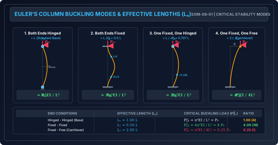
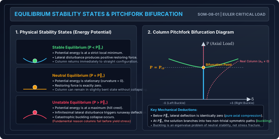
Figure 2: Column Stability States & Pitchfork Bifurcation
The following diagram demonstrates the energy potential analogy (stable, neutral, and unstable equilibrium bowls) alongside the classical pitchfork bifurcation diagram of an axially loaded ideal column versus an imperfect real column.
8. Worked Numerical Examples
Example 1: Tubular Steel Column Under All Four End Conditions
Problem Statement: A hollow structural steel circular tube of outside diameter and wall thickness has an unsupported length .
Modulus of elasticity .
Determine the Euler critical buckling load and safe axial load with a factor of safety for:
- Both ends hinged.
- Both ends fixed.
- One end fixed, one end hinged.
- One end fixed, other end free.
Solution:
Step 1: Cross-Sectional Geometric Properties:
- Inside diameter: .
- Moment of Inertia :
Step 2: Flexural Rigidity ():
Step 3: Critical Loads for All 4 Cases ():
-
Both ends hinged ():
-
Both ends fixed ():
-
One end fixed, one hinged (): Using exact root :
(Using textbook approx )
-
One end fixed, other free ():
Example 2: Built-Up Laced Column with Equal Buckling Strength
Problem Statement: A built-up column of length is pinned at both ends. It consists of two Indian Standard Medium Channels (ISMC 250) placed back-to-back with a clear distance between their webs, connected by a standard lacing system.
The properties of a single ISMC 250 from IS Handbook No. 1 are:
- Area
- (about major centroidal axis)
- (about minor centroidal axis)
- Distance from back of web to centroid:
Given .
- Calculate the required clear spacing between the channel webs so that the column has equal buckling resistance about both and principal axes ().
- Calculate the corresponding Euler critical load .
          Y
          │
     ┌────┼────┐
     │ ◄s►│    │     ISMC 250 Channels
     │    │    │     Back-to-Back
 ────┼────┼────┼──── X
     │    │    │
     └────┼────┘
          │
Solution:
Step 1: Composite Moments of Inertia For two identical channels:
- Major axis : Since the centroidal -axis of both channels coincides with the composite -axis:
- Minor axis : By Parallel Axis Theorem, the centroid of each channel is at distance from the composite -axis:
Step 2: Condition for Maximum Column Efficiency ():
Divide by 2:
Since :
Step 3: Euler Critical Load : With , :
Key Design Insight: By spacing the channels at , the designer completely eliminates the weak-axis buckling liability. The built-up column achieves an astonishing 17.4-fold increase in capacity compared to two unspaced channels in contact (, where ).
Example 3: Error Analysis of Fixed-Pinned Transcendental Approximation
Problem Statement: A solid circular aluminum alloy rod () of diameter and length is rigidly clamped at its base and pinned at its top.
- Compute the exact Euler buckling load using the transcendental root .
- Compute the approximate buckling load using the standard formula .
- Calculate the percentage discrepancy and explain its significance in competitive exams.
Solution:
Step 1: Section Properties:
Step 2: Exact Critical Load ():
Step 3: Approximate Critical Load ():
Step 4: Discrepancy Percentage:
Exam Takeaway: The standard approximation underestimates the exact buckling capacity by approximately . While negligible in rough hand calculations, GATE CE and ESE questions that require Numerical Answer Type (NAT) precision within must be solved using or .
9. Comparative Analysis: Minimum Moment of Inertia Principle
Columns are free to buckle in any direction perpendicular to their longitudinal axis. Unless physically restrained by lateral bracing in a specific direction:
The Golden Rule of Column Buckling: An unbraced column always buckles about the minor principal axis—that is, the axis having the minimum moment of inertia () and corresponding least radius of gyration ().
Rectangular Section Comparison
For a column of width and depth ():
Since , always. Thus, without lateral bracing, the column will buckle perpendicular to the thinner dimension (about the -axis).
Bracing in the Weak Direction
If lateral supports (intermediate bracings) are introduced along the weak direction, the effective length in the -direction is reduced to , while in the strong direction it remains . Buckling will then occur in the mode that gives the lower critical load:
10. Common Misconceptions & Exam Pitfalls
[!WARNING] Pitfall 1: Using the Larger Moment of Inertia () in Buckling Formulas The most frequent error in competitive exams is substituting instead of for asymmetrical sections (I-beams, channels, angles). Unless braced, the column has zero capacity to resist buckling once exceeds the minor-axis critical load. Always identify .
[!CAUTION] Pitfall 2: Confusing Effective Length Factors () Remember:
- Fixed-Fixed: (Factor is , Capacity is hinged).
- Fixed-Free: (Factor is , Capacity is hinged). Students frequently invert these factors, writing for fixed-fixed!
[!NOTE] Pitfall 3: Assuming Euler Buckling Governs Short Columns Euler's formula assumes elastic behavior (). If slenderness ratio is small, Euler's formula yields a critical stress that exceeds the yield strength or ultimate crushing strength of the material, which is physical nonsense. Euler's formula is completely invalid for short columns ( for mild steel).
[!WARNING] Pitfall 4: Neglecting the Difference Between Theoretical and IS Design Values Theoretical values (, ) are based on 100% infinite rigidity of connections. In design exams (UPSC ESE Mains, State AE), IS 800:2007 design values (, ) must be cited when specifying actual member sizes.
11. Real-World Engineering Applications & Standard Codes
- Building Column Design in IS 800:2007 (Section 7):
- Structural steel columns are classified into 4 buckling curves () based on cross-section geometry, flange thickness, and residual stresses.
- Design compressive strength , where .
- Reinforced Concrete Columns in IS 456:2000 (Clause 25.1.2):
- A compression member is classed as "short" when both slenderness ratios and are less than 12. If either exceeds 12, it is designed as a slender column with additional second-order moments ( effects).
- Transmission Towers and Trusses:
- Slender angle sections used as tower diagonals must have their effective length adjusted for bolt end fixity (IS 802 Part 1).
12. Quick Revision Summary & Formula Sheet
| Property / Boundary Condition | Formula / Expression | Value / Factor |
|---|---|---|
| Euler's Generalized Formula | or | |
| Both Ends Hinged / Pinned | ||
| Both Ends Fixed | ||
| One Fixed, One Hinged | (Exact: ) | |
| One Fixed, One Free (Cantilever) | ||
| Relative Strength Ratio | Fixed-Fixed : Fixed-Hinged : Hinged-Hinged : Fixed-Free | (or ) |
| Radius of Gyration | or | |
| Critical Buckling Stress | ||
| Slenderness Ratio | Dimensionless |