SOM-05-01 Chapter 05 · Shear Stresses

Transverse Shear Stress Formula and Shear Flow

1. Topic Metadata

Field Detail
Topic Identifier SOM-05-01
Subject Strength of Materials / Solid Mechanics
Chapter Shear Stresses in Beams (05_shear_stresses)
Difficulty Level Intermediate to Advanced
Target Examinations GATE CE, UPSC ESE, SSC JE, State AE/JE, RRB JE
Primary Prerequisites Shear Force & Bending Moment Diagrams (SOM-03-02), Pure Bending Theory (SOM-04-01), Centroid & First Moment of Area (QQ)
Benchmark Formulas Jourawski's Shear Formula: τ=VQIb\tau = \frac{V Q}{I b}; Shear Flow: q=τ⋅b=VQIq = \tau \cdot b = \frac{V Q}{I}; Fastener Pitch: p≤nRvq=nRvIVQp \le \frac{n R_v}{q} = \frac{n R_v I}{V Q}; Rectangular Peak: τmax⁡=1.5τavg\tau_{\max} = 1.5 \tau_{\text{avg}}; Middle Half Shear: Vmid=1116V=68.75%VV_{\text{mid}} = \frac{11}{16} V = 68.75\% V
Authoritative Code References IS 800:2007 (Cl. 8.4, Cl. 10.2, Cl. 10.3), IS 456:2000 (Cl. 40), IS 3629:1986, IRC:24-2010

2. Physical Mechanics & Theoretical Foundation

In Chapter 04, we analyzed pure bending, where the bending moment is constant (M=constM = \text{const}) and the vertical shear force is strictly zero (V=dM/dx=0V = dM/dx = 0). In actual engineering practice, however, beams almost universally support lateral loads (such as point loads and distributed dead/live loads) that induce non-zero transverse shear forces (V(x)≠0V(x) \neq 0). This state of loading is known as non-uniform bending or flexure with shear.

                        TRANSVERSE SHEAR IN A BEAM:
               w(x)
        ↓↓↓↓↓↓↓↓↓↓↓↓↓↓↓↓
        ══════════════════════════════════════
        ▲                                    ▲
        │                                    │

             Transverse Shear Force V(x) = dM/dx ≠ 0
             └──> Induces Vertical Shear Stresses τ_xy
             └──> Accompanied by Complementary Horizontal Shear τ_yx

2.1 The Phenomenon of Horizontal Interlayer Slip

To visualize why horizontal shear stresses must exist inside a flexural member, imagine a beam constructed of individual unglued horizontal wooden planks stacked loosely on top of one another. When a lateral downward load is applied:

  1. Each individual plank bends independently.
  2. The bottom fibers of the top plank elongate in tension, while the top fibers of the bottom plank contract in compression.
  3. As a result, the adjacent contacting surfaces slide past each other (interlayer slip occurs).
  4. When the planks are glued, bolted, or cast monolithically as a solid beam, this relative horizontal sliding is strictly prevented. Internal horizontal shear stresses (τyx\tau_{yx}) develop along every horizontal longitudinal bedding plane to maintain cross-sectional continuity.

2.2 Complementary Shear Stress Equality (Cauchy's Reciprocal Relation)

From Cauchy's fundamental stress tensor equilibrium (ΣMz=0\Sigma M_z = 0 on an infinitesimal differential element):

τxy=τyx\tau_{xy} = \tau_{yx}

The horizontal longitudinal shear stress (τyx\tau_{yx}) acting along the bedding plane is strictly identical in magnitude to the vertical transverse shear stress (τxy\tau_{xy}) acting across the vertical cross-section.

Crucial Engineering Consequence: Even though civil engineers typically apply vertical loads to a beam, timber beams frequently fail by horizontal shear splitting along the longitudinal wood grain because wood has vastly lower shear strength along its parallel grain fibers (τallow,∥≈1.0−1.5 MPa\tau_{\text{allow}, \parallel} \approx 1.0 - 1.5\text{ MPa}) than across its perpendicular fibers.


3. Mathematical Derivations & Governing Equations

3.1 Derivation of Jourawski's Shear Formula (τ=VQIb\tau = \frac{V Q}{I b})

Consider a prismatic beam subjected to an arbitrary transverse loading. Isolate a differential beam slice of length dxdx between two vertical cross-sections located at xx and x+dxx + dx.

                 Left Face (x)                 Right Face (x + dx)
              ┌──────────────────────────────────────────────────┐  Top
              │    M(x)                          M(x) + dM       │
         y₁ ──┼ - - - - - - - - - - - - - - - - - - - - - - - - -┼── Level y₁
              │                                                  │
         N.A. ┼──────────────────────────────────────────────────┼── N.A.
              │                                                  │
              └──────────────────────────────────────────────────┘  Bottom
                     <──────────── dx ────────────>

Step 1: Normal Force Distribution on Sliced Upper Element

Now isolate the upper portion of this differential element lying between an arbitrary fiber level y=y1y = y_1 and the top extreme fiber y=ymax⁡y = y_{\max}. From the flexure formula (σ=MyI\sigma = \frac{M y}{I}):

  • Normal stress on the left vertical face: σ1(y)=MyI\sigma_1(y) = \frac{M y}{I}
  • Normal stress on the right vertical face: σ2(y)=(M+dM)yI\sigma_2(y) = \frac{(M + dM) y}{I}

Total compressive normal force acting on the left vertical face of the sliced block:

F1=∫y1ymax⁡σ1 dA=∫y1ymax⁡(MyI) dA=MI∫y1ymax⁡y dAF_1 = \int_{y_1}^{y_{\max}} \sigma_1 \, dA = \int_{y_1}^{y_{\max}} \left(\frac{M y}{I}\right) \, dA = \frac{M}{I} \int_{y_1}^{y_{\max}} y \, dA

Total compressive normal force acting on the right vertical face of the sliced block:

F2=∫y1ymax⁡σ2 dA=M+dMI∫y1ymax⁡y dAF_2 = \int_{y_1}^{y_{\max}} \sigma_2 \, dA = \frac{M + dM}{I} \int_{y_1}^{y_{\max}} y \, dA

Step 2: The First Moment of Area (QQ)

Define the first moment of the cut area (A′A') about the neutral axis:

Q=∫y1ymax⁡y dA=A′⋅yˉ′Q = \int_{y_1}^{y_{\max}} y \, dA = A' \cdot \bar{y}'

where:

  • A′A' is the area of the cross-section located strictly above (or below) the cut level y1y_1.
  • yˉ′\bar{y}' is the centroidal distance of area A′A' measured from the neutral axis.

Substituting QQ into the force expressions:

F1=MIQF_1 = \frac{M}{I} Q F2=M+dMIQF_2 = \frac{M + dM}{I} Q

Step 3: Horizontal Force Unbalance

Because the bending moment increases from MM to M+dMM + dM, the compressive force on the right face exceeds that on the left face:

ΔF=F2−F1=dMIQ\Delta F = F_2 - F_1 = \frac{dM}{I} Q

This unbalanced horizontal force ΔF\Delta F must be equilibrated by the horizontal shear force acting on the horizontal cut plane of area dAcut=b⋅dxdA_{\text{cut}} = b \cdot dx, where bb is the cross-sectional width at level y1y_1:

Hshear=τ⋅(b⋅dx)H_{\text{shear}} = \tau \cdot (b \cdot dx)

Step 4: Horizontal Equilibrium (ΣFx=0\Sigma F_x = 0)

Equating the horizontal forces:

ΣFx=0  ⟹  F2−F1−τ⋅(b⋅dx)=0\Sigma F_x = 0 \implies F_2 - F_1 - \tau \cdot (b \cdot dx) = 0 dMIQ=τ⋅b⋅dx\frac{dM}{I} Q = \tau \cdot b \cdot dx τ=(dMdx)⋅QIb\tau = \left(\frac{dM}{dx}\right) \cdot \frac{Q}{I b}

Recalling the differential equilibrium relation from beam mechanics (dMdx=V\frac{dM}{dx} = V):

τ=VQIb\tau = \frac{V Q}{I b}

This is the celebrated Jourawski Transverse Shear Formula (also known as the Colignon-Jourawski equation).


3.2 Shear Flow (qq)

In structural design, particularly for built-up and thin-walled members, it is exceedingly convenient to define the shear force per unit longitudinal length, known as shear flow (qq):

q=τ⋅b=VQI[Units: N/mm, kN/m, or lb/in]q = \tau \cdot b = \frac{V Q}{I} \quad [\text{Units: N/mm, kN/m, or lb/in}]

Properties of Shear Flow:

  1. Independent of Interface Width: Shear flow qq does not depend on the local contact width bb, making it ideal for evaluating connections (such as nails, bolts, screws, and welds) where the interface width may be irregular or difficult to define.
  2. Fastener Pitch (Spacing pp) Equation: If a built-up beam is assembled by fasteners placed at a longitudinal pitch spacing pp, the horizontal shear force transmitted over a length pp is: Fshear=q⋅pF_{\text{shear}} = q \cdot p If each pitch cross-section contains nn fasteners (e.g., bolts in single or double shear), each with an allowable shear capacity RvR_v: q⋅p≤n⋅Rvq \cdot p \le n \cdot R_v p≤n⋅Rvq=n⋅Rv⋅IVQp \le \frac{n \cdot R_v}{q} = \frac{n \cdot R_v \cdot I}{V Q}

3.3 Boundary Conditions for Transverse Shear

  1. Free Surfaces (y=±ymax⁡y = \pm y_{\max}): At the extreme top and bottom fibers, the cut area above the surface is zero (A′=0  ⟹  Q=0A' = 0 \implies Q = 0). τ(ytop)=0,τ(ybot)=0\tau(y_{\text{top}}) = 0, \quad \tau(y_{\text{bot}}) = 0 Transverse shear stress is identically zero at the outer top and bottom free surfaces.
  2. Neutral Axis (y=0y = 0): For cross-sections symmetric about the neutral axis (such as rectangles, circles, and I-sections), QQ attains its global maximum at the neutral axis (Qmax⁡=QNAQ_{\max} = Q_{\text{NA}}). Consequently, shear stress τ\tau reaches its maximum value at the neutral axis (provided the width bb does not flare out abruptly).

4. Engineering Assumptions & Validity Limits

  1. Prismatic Member & Plane of Symmetry: The beam is straight, prismatic, and loaded in a plane of structural symmetry so that twisting does not accompany bending.
  2. Uniform Shear Across Width: The shear stress τ\tau is assumed to be uniform across the cross-sectional width bb. This assumption is highly accurate when the width bb is small relative to the depth dd (b≤d/2b \le d/2). For very wide flanges, shear lag causes τ\tau to vary across the width.
  3. Linear Elastic Behavior: The material obeys Hooke's law, and the normal stresses follow the flexure equation σ=My/I\sigma = M y / I.
  4. Perpendicular Flange-Web Interfaces: In rolled steel and flanged sections, the formula assumes rectangular intersections. Fillet transitions and stress concentrations at re-entrant corners are accounted for via code provisions (IS 800:2007).

5. SVG Technical Illustrations & Diagrammatic Analysis

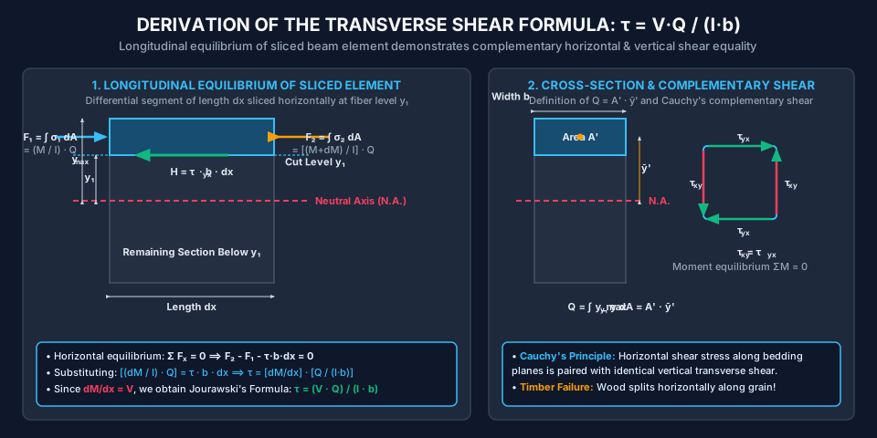
Figure 1: Differential Element Equilibrium & Cauchy's Complementary Shear

The diagram below illustrates the horizontal force unbalance ΔF=dMIQ\Delta F = \frac{dM}{I}Q acting on a sliced element and its equilibration by horizontal shear force τ⋅b⋅dx\tau \cdot b \cdot dx, along with the complementary shear relationship τxy=τyx\tau_{xy} = \tau_{yx}.

Transverse Shear Derivation Element

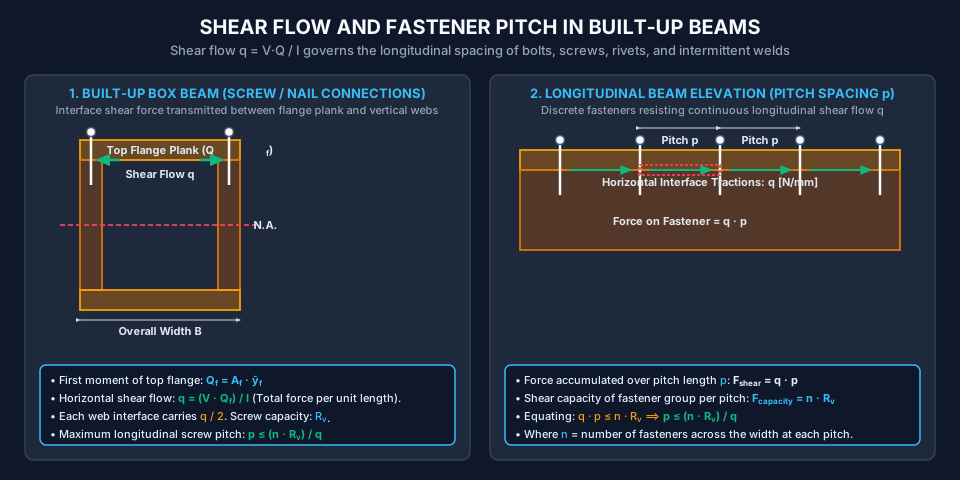
Figure 2: Shear Flow and Fastener Pitch Spacing in Built-Up Beams

The diagram below demonstrates how shear flow q=VQIq = \frac{VQ}{I} is transmitted across horizontal interfaces in built-up box girders, and how the longitudinal fastener pitch p≤nRvqp \le \frac{nR_v}{q} is determined.

Shear Flow and Fastener Spacing

6. Solved Numerical Examples (Python-Verified)

Example 1: Rectangular Timber Beam — Exact Shear Profile & The Middle-Half Theorem

Problem Statement: A rectangular timber beam has a cross-section of width b=150.0 mmb = 150.0\text{ mm} and depth d=300.0 mmd = 300.0\text{ mm}. At a given cross-section along the span, the beam is subjected to a vertical shear force V=45.0 kNV = 45.0\text{ kN} (45,000.0 N45,000.0\text{ N}).

  1. Calculate the nominal average shear stress τavg=V/A\tau_{\text{avg}} = V / A.
  2. Calculate the maximum shear stress τmax⁡\tau_{\max} occurring at the neutral axis using Jourawski's formula, and confirm the canonical ratio τmax⁡τavg=1.50\frac{\tau_{\max}}{\tau_{\text{avg}}} = 1.50.
  3. Compute the shear stress at a distance y1=75.0 mmy_1 = 75.0\text{ mm} above the neutral axis (d/4d/4 from NA), and at y1=150.0 mmy_1 = 150.0\text{ mm} (extreme top fiber).
  4. Calculate the total vertical shear force carried by the middle half of the beam depth (between y=−75.0 mmy = -75.0\text{ mm} and y=+75.0 mmy = +75.0\text{ mm}) by integrating ∫τ dA\int \tau \, dA, and compute the exact percentage of the total shear force carried by this central zone.

Solution:

Step 1: Nominal Average Shear Stress:

A=b×d=150.0 mm×300.0 mm=45,000.0 mm2A = b \times d = 150.0\text{ mm} \times 300.0\text{ mm} = 45,000.0\text{ mm}^2 τavg=VA=45,000.0 N45,000.0 mm2=1.0000 N/mm2 (MPa)\tau_{\text{avg}} = \frac{V}{A} = \frac{45,000.0\text{ N}}{45,000.0\text{ mm}^2} = \mathbf{1.0000\text{ N/mm}^2\text{ (MPa)}}

Step 2: Maximum Shear Stress at Neutral Axis (y=0y = 0): Second moment of area:

I=bd312=150.0×(300.0)312=150.0×27.0×10612=337.50×106 mm4I = \frac{b d^3}{12} = \frac{150.0 \times (300.0)^3}{12} = \frac{150.0 \times 27.0 \times 10^6}{12} = 337.50 \times 10^6\text{ mm}^4

Area above the neutral axis:

A′=b×d2=150.0×150.0=22,500.0 mm2A' = b \times \frac{d}{2} = 150.0 \times 150.0 = 22,500.0\text{ mm}^2

Centroid of area A′A' from neutral axis:

yˉ′=d/22=150.02=75.0 mm\bar{y}' = \frac{d/2}{2} = \frac{150.0}{2} = 75.0\text{ mm}

First moment of area at neutral axis:

QNA=A′⋅yˉ′=22,500.0 mm2×75.0 mm=1.6875×106 mm3Q_{\text{NA}} = A' \cdot \bar{y}' = 22,500.0\text{ mm}^2 \times 75.0\text{ mm} = 1.6875 \times 10^6\text{ mm}^3

(Closed-form formula: QNA=bd28=150.0×90,000.08=1.6875×106 mm3Q_{\text{NA}} = \frac{b d^2}{8} = \frac{150.0 \times 90,000.0}{8} = 1.6875 \times 10^6\text{ mm}^3, exact match!)

Maximum shear stress:

τmax⁡=VQNAIb=(45,000.0 N)×(1.6875×106 mm3)(337.50×106 mm4)×(150.0 mm)\tau_{\max} = \frac{V Q_{\text{NA}}}{I b} = \frac{(45,000.0\text{ N}) \times (1.6875 \times 10^6\text{ mm}^3)}{(337.50 \times 10^6\text{ mm}^4) \times (150.0\text{ mm})} τmax⁡=75.9375×10950.625×109=1.5000 N/mm2 (MPa)\tau_{\max} = \frac{75.9375 \times 10^9}{50.625 \times 10^9} = \mathbf{1.5000\text{ N/mm}^2\text{ (MPa)}}

Ratio:

τmax⁡τavg=1.50001.0000=1.5000=32\frac{\tau_{\max}}{\tau_{\text{avg}}} = \frac{1.5000}{1.0000} = \mathbf{1.5000} = \frac{3}{2}

Step 3: Shear Stress at Intermediate Level y1=75.0 mmy_1 = 75.0\text{ mm}: Area above y1=75.0 mmy_1 = 75.0\text{ mm}: Height of slice: h′=d2−y1=150.0−75.0=75.0 mmh' = \frac{d}{2} - y_1 = 150.0 - 75.0 = 75.0\text{ mm}.

A1′=b×h′=150.0×75.0=11,250.0 mm2A_1' = b \times h' = 150.0 \times 75.0 = 11,250.0\text{ mm}^2

Centroid distance from NA:

yˉ1′=y1+h′2=75.0+37.5=112.50 mm\bar{y}_1' = y_1 + \frac{h'}{2} = 75.0 + 37.5 = 112.50\text{ mm} Qy1=A1′⋅yˉ1′=11,250.0×112.50=1.265625×106 mm3Q_{y_1} = A_1' \cdot \bar{y}_1' = 11,250.0 \times 112.50 = 1.265625 \times 10^6\text{ mm}^3

Shear stress at y1=75.0 mmy_1 = 75.0\text{ mm}:

τ(y1)=VQy1Ib=45,000.0×1.265625×106337.50×106×150.0=56.953125×10950.625×109=1.1250 N/mm2 (MPa)\tau(y_1) = \frac{V Q_{y_1}}{I b} = \frac{45,000.0 \times 1.265625 \times 10^6}{337.50 \times 10^6 \times 150.0} = \frac{56.953125 \times 10^9}{50.625 \times 10^9} = \mathbf{1.1250\text{ N/mm}^2\text{ (MPa)}}

(Direct formula check: τ(y)=τmax⁡[1−(2yd)2]=1.50×[1−(0.5)2]=1.50×0.75=1.1250 MPa\tau(y) = \tau_{\max}\left[1 - \left(\frac{2y}{d}\right)^2\right] = 1.50 \times \left[1 - (0.5)^2\right] = 1.50 \times 0.75 = 1.1250\text{ MPa}, exact match!)

At the extreme top fiber (y1=150.0 mmy_1 = 150.0\text{ mm}):

Q=0  ⟹  τ(150.0)=0.0000 MPaQ = 0 \implies \tau(150.0) = \mathbf{0.0000\text{ MPa}}

Step 4: Shear Force Carried by the Middle Half of Beam Depth: The middle half extends from y=−d/4=−75.0 mmy = -d/4 = -75.0\text{ mm} to y=+d/4=+75.0 mmy = +d/4 = +75.0\text{ mm}.

Vmid=∫−d/4d/4τ(y)⋅(b dy)=2∫0d/4{32Vbd[1−4y2d2]}b dyV_{\text{mid}} = \int_{-d/4}^{d/4} \tau(y) \cdot (b \, dy) = 2 \int_0^{d/4} \left\{\frac{3}{2} \frac{V}{bd} \left[1 - \frac{4 y^2}{d^2}\right]\right\} b \, dy Vmid=3Vd∫0d/4(1−4y2d2)dy=3Vd[y−4y33d2]0d/4V_{\text{mid}} = \frac{3 V}{d} \int_0^{d/4} \left(1 - \frac{4 y^2}{d^2}\right) dy = \frac{3 V}{d} \left[ y - \frac{4 y^3}{3 d^2} \right]_0^{d/4} Vmid=3Vd[d4−4(d3/64)3d2]=3Vd[d4−d48]=3Vd[11d48]=3348V=1116VV_{\text{mid}} = \frac{3 V}{d} \left[ \frac{d}{4} - \frac{4 (d^3 / 64)}{3 d^2} \right] = \frac{3 V}{d} \left[ \frac{d}{4} - \frac{d}{48} \right] = \frac{3 V}{d} \left[ \frac{11 d}{48} \right] = \frac{33}{48} V = \mathbf{\frac{11}{16} V}

Numerical value:

Vmid=1116×45,000.0 N=30,937.50 N=30.94 kNV_{\text{mid}} = \frac{11}{16} \times 45,000.0\text{ N} = \mathbf{30,937.50\text{ N}} = \mathbf{30.94\text{ kN}}

Percentage of total shear:

VmidV×100%=1116×100%=68.75%\frac{V_{\text{mid}}}{V} \times 100\% = \frac{11}{16} \times 100\% = \mathbf{68.75\%}

Classic Competitive Exam Result: The central 50%50\% of the depth of a rectangular beam carries 68.75%68.75\% (≈69%\approx 69\%) of the total transverse shear force!


Example 2: Built-Up Wooden Box Beam — Screw Fastener Pitch Sizing

Problem Statement: A built-up box beam is fabricated from four structural timber planks:

  • Top and bottom flange planks: B=200.0 mmB = 200.0\text{ mm} wide ×tf=25.0 mm\times t_f = 25.0\text{ mm} thick.
  • Two vertical web planks: tw=25.0 mmt_w = 25.0\text{ mm} thick ×hw=200.0 mm\times h_w = 200.0\text{ mm} deep sandwiched between the flanges. Total outer dimensions: width B=200.0 mmB = 200.0\text{ mm}, overall depth H=250.0 mmH = 250.0\text{ mm}. Inner hollow void: width bi=150.0 mmb_i = 150.0\text{ mm}, depth hi=200.0 mmh_i = 200.0\text{ mm}. The top flange plank is fastened to both vertical webs using high-tensile wood screws. Each screw has an allowable single shear capacity Rv=1.80 kNR_v = 1.80\text{ kN} (1800.0 N1800.0\text{ N}). At each longitudinal fastener cross-section, two screws are driven (n=2n = 2, one into each web plank). At a support section, the beam resists a vertical shear force V=15.0 kNV = 15.0\text{ kN} (15,000.0 N15,000.0\text{ N}).
  1. Calculate the second moment of area II of the hollow box section about the neutral axis.
  2. Determine the first moment of area QfQ_f of the top flange plank about the neutral axis.
  3. Calculate the shear flow qq transmitted across the horizontal interface between the top flange and the two webs.
  4. Calculate the maximum permissible longitudinal screw pitch spacing pp.

Solution:

Step 1: Moment of Inertia of Box Section: Outer rectangle: B=200.0 mmB = 200.0\text{ mm}, H=250.0 mmH = 250.0\text{ mm}. Inner void: bi=B−2tw=200.0−50.0=150.0 mmb_i = B - 2 t_w = 200.0 - 50.0 = 150.0\text{ mm}, hi=H−2tf=250.0−50.0=200.0 mmh_i = H - 2 t_f = 250.0 - 50.0 = 200.0\text{ mm}.

I=BH3−bihi312=200.0×(250.0)3−150.0×(200.0)312I = \frac{B H^3 - b_i h_i^3}{12} = \frac{200.0 \times (250.0)^3 - 150.0 \times (200.0)^3}{12} 200.0×(250.0)3=200.0×15.625×106=3,125.0×106 mm4200.0 \times (250.0)^3 = 200.0 \times 15.625 \times 10^6 = 3,125.0 \times 10^6\text{ mm}^4 150.0×(200.0)3=150.0×8.0×106=1,200.0×106 mm4150.0 \times (200.0)^3 = 150.0 \times 8.0 \times 10^6 = 1,200.0 \times 10^6\text{ mm}^4 I=3,125.0×106−1,200.0×10612=1,925.0×10612=160.4167×106 mm4I = \frac{3,125.0 \times 10^6 - 1,200.0 \times 10^6}{12} = \frac{1,925.0 \times 10^6}{12} = \mathbf{160.4167 \times 10^6\text{ mm}^4}

Step 2: First Moment of Area (QfQ_f) of Top Flange: Area of top flange plank:

Af=B×tf=200.0 mm×25.0 mm=5,000.0 mm2A_f = B \times t_f = 200.0\text{ mm} \times 25.0\text{ mm} = 5,000.0\text{ mm}^2

Distance from neutral axis to centroid of top flange plank:

yˉf=H2−tf2=125.0−12.5=112.50 mm\bar{y}_f = \frac{H}{2} - \frac{t_f}{2} = 125.0 - 12.5 = 112.50\text{ mm} Qf=Af⋅yˉf=5,000.0 mm2×112.50 mm=562,500.0 mm3=5.625×105 mm3Q_f = A_f \cdot \bar{y}_f = 5,000.0\text{ mm}^2 \times 112.50\text{ mm} = \mathbf{562,500.0\text{ mm}^3} = \mathbf{5.625 \times 10^5\text{ mm}^3}

Step 3: Horizontal Shear Flow (qq):

q=VQfI=(15,000.0 N)×(562,500.0 mm3)160.4167×106 mm4=8.4375×109160.4167×106=52.5974 N/mmq = \frac{V Q_f}{I} = \frac{(15,000.0\text{ N}) \times (562,500.0\text{ mm}^3)}{160.4167 \times 10^6\text{ mm}^4} = \frac{8.4375 \times 10^9}{160.4167 \times 10^6} = \mathbf{52.5974\text{ N/mm}}

(Note: Each individual web interface carries half of this shear flow: qsingle=q/2=26.30 N/mmq_{\text{single}} = q / 2 = 26.30\text{ N/mm}.)

Step 4: Maximum Screw Pitch (pp): Total fastener shear capacity per pitch cross-section (two screws):

Fcap=n⋅Rv=2×1800.0 N=3,600.0 NF_{\text{cap}} = n \cdot R_v = 2 \times 1800.0\text{ N} = 3,600.0\text{ N}

Equating shear capacity to shear demand:

q⋅p≤n⋅Rv  ⟹  p≤n⋅Rvq=3,600.0 N52.5974 N/mm=68.44 mmq \cdot p \le n \cdot R_v \implies p \le \frac{n \cdot R_v}{q} = \frac{3,600.0\text{ N}}{52.5974\text{ N/mm}} = \mathbf{68.44\text{ mm}}

Specification: Provide pairs of wood screws at a longitudinal pitch of p=65 mmp = 65\text{ mm} on centers along the beam span.


Example 3: Built-Up Steel Plate Girder — Cover Plate Rivet Pitch Sizing

Problem Statement: A built-up structural steel plate girder carries an operating vertical shear force V=180.0 kNV = 180.0\text{ kN} (180,000.0 N180,000.0\text{ N}). The girder is constructed from:

  • A central web plate: 10.0 mm10.0\text{ mm} thick ×368.0 mm\times 368.0\text{ mm} deep.
  • Two I-beam flanges: Bf=200.0 mmB_f = 200.0\text{ mm} wide ×tf=16.0 mm\times t_f = 16.0\text{ mm} thick (total depth of bare section =400.0 mm= 400.0\text{ mm}).
  • Two additional cover plates: Bc=240.0 mmB_c = 240.0\text{ mm} wide ×tc=12.0 mm\times t_c = 12.0\text{ mm} thick, attached to the top and bottom flanges. Total overall depth is Dtotal=400.0+2(12.0)=424.0 mmD_{\text{total}} = 400.0 + 2(12.0) = 424.0\text{ mm}. The cover plates are connected to the flanges using 20 mm20\text{ mm} diameter structural rivets in pairs (n=2n = 2). The allowable shear value of a single rivet is Rv=35.0 kNR_v = 35.0\text{ kN} (35,000.0 N35,000.0\text{ N}).
  1. Calculate the second moment of area of the complete girder ItotalI_{\text{total}}.
  2. Calculate the shear flow qcq_c transmitted between the top cover plate and the flange.
  3. Determine the required pitch spacing pp of the rivets connecting the cover plates.
  4. Calculate the maximum shear stress τmax⁡\tau_{\max} occurring in the web plate at the neutral axis.

Solution:

Step 1: Moment of Inertia of Complete Girder (ItotalI_{\text{total}}):

  • Bare I-section (400 mm400\text{ mm} deep, 200 mm200\text{ mm} wide, 10 mm10\text{ mm} web, 16 mm16\text{ mm} flanges):

    Ibare=BfD3−(Bf−tw)hw312=200.0×(400.0)3−190.0×(368.0)312I_{\text{bare}} = \frac{B_f D^3 - (B_f - t_w) h_w^3}{12} = \frac{200.0 \times (400.0)^3 - 190.0 \times (368.0)^3}{12} 200.0×(400.0)3=12,800.0×106 mm4200.0 \times (400.0)^3 = 12,800.0 \times 10^6\text{ mm}^4 190.0×(368.0)3=190.0×49,836,032.0=9,468.846×106 mm4190.0 \times (368.0)^3 = 190.0 \times 49,836,032.0 = 9,468.846 \times 10^6\text{ mm}^4 Ibare=12,800.0×106−9,468.846×10612=277.596×106 mm4I_{\text{bare}} = \frac{12,800.0 \times 10^6 - 9,468.846 \times 10^6}{12} = 277.596 \times 10^6\text{ mm}^4
  • Cover Plates (Two plates, 240×12 mm240 \times 12\text{ mm}, centroid at y=200.0+6.0=206.0 mmy = 200.0 + 6.0 = 206.0\text{ mm}):

    Ac=Bc×tc=240.0×12.0=2,880.0 mm2A_c = B_c \times t_c = 240.0 \times 12.0 = 2,880.0\text{ mm}^2 Ic,own=2×(240.0×12.0312)=69,120.0 mm4=0.069×106 mm4I_{c, \text{own}} = 2 \times \left(\frac{240.0 \times 12.0^3}{12}\right) = 69,120.0\text{ mm}^4 = 0.069 \times 10^6\text{ mm}^4 Ic,d2=2×[Ac⋅(206.0)2]=2×[2,880.0×42,436.0]=244.431×106 mm4I_{c, d^2} = 2 \times \left[A_c \cdot (206.0)^2\right] = 2 \times [2,880.0 \times 42,436.0] = 244.431 \times 10^6\text{ mm}^4 Ic=0.069×10⁶+244.431×106=244.500×106 mm4I_c = 0.069 \times 10^6 + 244.431 \times 10^6 = 244.500 \times 10^6\text{ mm}^4

Total moment of inertia:

Itotal=Ibare+Ic=277.596×10⁶+244.500×106=522.096×106 mm4I_{\text{total}} = I_{\text{bare}} + I_c = 277.596 \times 10^6 + 244.500 \times 10^6 = \mathbf{522.096 \times 10^6\text{ mm}^4}

Step 2: Shear Flow Between Cover Plate and Flange (qcq_c): First moment of area of the top cover plate about the neutral axis:

Qc=Ac⋅yc=2,880.0 mm2×206.0 mm=593,280.0 mm3Q_c = A_c \cdot y_c = 2,880.0\text{ mm}^2 \times 206.0\text{ mm} = \mathbf{593,280.0\text{ mm}^3}

Shear flow at cover plate interface:

qc=VQcItotal=(180,000.0 N)×(593,280.0 mm3)522.096×106 mm4=106.7904×109522.096×106=204.541 N/mmq_c = \frac{V Q_c}{I_{\text{total}}} = \frac{(180,000.0\text{ N}) \times (593,280.0\text{ mm}^3)}{522.096 \times 10^6\text{ mm}^4} = \frac{106.7904 \times 10^9}{522.096 \times 10^6} = \mathbf{204.541\text{ N/mm}}

Step 3: Rivet Pitch Spacing (pp): Two rivets per pitch (n=2n = 2):

Fcap=n⋅Rv=2×35,000.0 N=70,000.0 NF_{\text{cap}} = n \cdot R_v = 2 \times 35,000.0\text{ N} = 70,000.0\text{ N} p≤n⋅Rvqc=70,000.0 N204.541 N/mm=342.23 mmp \le \frac{n \cdot R_v}{q_c} = \frac{70,000.0\text{ N}}{204.541\text{ N/mm}} = \mathbf{342.23\text{ mm}}

According to IS 800:2007 (Cl. 10.2.2), the maximum pitch of fasteners in tension/compression members must not exceed 16t16 t or 200 mm200\text{ mm} (where t=12 mm  ⟹  16×12=192 mmt = 12\text{ mm} \implies 16 \times 12 = 192\text{ mm}). Therefore, code provisions govern over pure shear demand:

pspec=180 mm\mathbf{p_{\text{spec}} = 180\text{ mm}}

Step 4: Maximum Shear Stress in Web at Neutral Axis: First moment of total area above neutral axis (Qtotal, NAQ_{\text{total, NA}}):

  • Cover plate: Qc=593,280.0 mm3Q_c = 593,280.0\text{ mm}^3
  • Flange plate (200×16 mm200 \times 16\text{ mm}, centroid at y=192.0 mmy = 192.0\text{ mm}): Qf=(200.0×16.0)×192.0=3,200.0×192.0=614,400.0 mm3Q_f = (200.0 \times 16.0) \times 192.0 = 3,200.0 \times 192.0 = 614,400.0\text{ mm}^3
  • Upper half of web (10 mm10\text{ mm} thick ×184.0 mm\times 184.0\text{ mm} high, centroid at y=92.0 mmy = 92.0\text{ mm}): Qw=(10.0×184.0)×92.0=1,840.0×92.0=169,280.0 mm3Q_w = (10.0 \times 184.0) \times 92.0 = 1,840.0 \times 92.0 = 169,280.0\text{ mm}^3
Qtotal, NA=593,280.0+614,400.0+169,280.0=1,376,960.0 mm3Q_{\text{total, NA}} = 593,280.0 + 614,400.0 + 169,280.0 = \mathbf{1,376,960.0\text{ mm}^3}

Web thickness at NA is tw=10.0 mmt_w = 10.0\text{ mm}.

τmax⁡,web=VQtotal, NAItotaltw=(180,000.0 N)×(1,376,960.0 mm3)(522.096×106 mm4)×(10.0 mm)\tau_{\max, \text{web}} = \frac{V Q_{\text{total, NA}}}{I_{\text{total}} t_w} = \frac{(180,000.0\text{ N}) \times (1,376,960.0\text{ mm}^3)}{(522.096 \times 10^6\text{ mm}^4) \times (10.0\text{ mm})} τmax⁡,web=247.8528×1095.22096×109=47.47 N/mm2 (MPa)\tau_{\max, \text{web}} = \frac{247.8528 \times 10^9}{5.22096 \times 10^9} = \mathbf{47.47\text{ N/mm}^2\text{ (MPa)}}

Safe against permissible shear stress for structural steel (τallow=0.45fy=112.5 MPa\tau_{\text{allow}} = 0.45 f_y = 112.5\text{ MPa} for E250 steel).


7. Engineering Applications & Real-World Case Studies

  1. Pre-Engineered Building (PEB) Girders & Plate Girders (IS 800:2007 Cl. 8.4): Heavy industrial crane girders rely on Jourawski's shear flow qq to calculate the required weld throat thickness for continuous automated submerged arc welding (SAW) joining the web plate to the flanges.
  2. Timber Glulam & Flitched Box Girders (IS 3629 / Eurocode 5): Glued-laminated (Glulam) bridge stringers and boxed plywood joists are evaluated for longitudinal rolling shear along horizontal glue lines. Glue line capacity must exceed q=VQ/Iq = V Q / I.
  3. Composite Concrete Slab on Steel I-Beams (IRC:22-2015 / IS 11384): Headed shear studs welded to the top flange of steel bridge girders resist horizontal shear flow qq to ensure composite action between the cast-in-place concrete deck slab and the steel girders under rolling vehicle axle loads.
  4. Aircraft Wing Spars and Box Beams: Aluminum alloy wing spar webs carry transverse lift shear forces. Rivet spacing connecting the upper and lower spar caps (flanges) to the thin shear web is sized precisely via the shear flow formula p=Rv/qp = R_v / q.

8. Comparative Analysis & Summary Matrix

Cross-Section Type Neutral Axis First Moment Qmax⁡Q_{\max} Maximum Shear Stress τmax⁡\tau_{\max} Ratio τmax⁡/τavg\tau_{\max} / \tau_{\text{avg}} Location of τmax⁡\tau_{\max}
Solid Rectangle (b×db \times d) bd28\frac{b d^2}{8} 32Vbd\frac{3}{2} \frac{V}{b d} 1.501.50 (3/23/2) At Neutral Axis (y=0y = 0)
Solid Circle (Dia DD) D312\frac{D^3}{12} 43VπD2/4\frac{4}{3} \frac{V}{\pi D^2 / 4} 1.331.33 (4/34/3) At Neutral Axis (y=0y = 0)
Thin Circular Tube (R,tR, t) 2R2t2 R^2 t 2VπRt\frac{2 V}{\pi R t} 2.002.00 At Neutral Axis (y=0y = 0)
Isosceles Triangle (b×hb \times h) bh224\frac{b h^2}{24} (at h/3h/3) 32Vbh/2\frac{3}{2} \frac{V}{b h / 2} (at h/2h/2) 1.501.50 (at h/2h/2) At mid-depth h/2h/2 (NOT at NA!)
Diamond / Square on Diagonal a362\frac{a^3}{6\sqrt{2}} 98τavg\frac{9}{8} \tau_{\text{avg}} (at 3h/83h/8) 1.1251.125 (9/89/8) At 3/83/8 depth (NOT at NA!)
Steel I-Beam (B,D,tf,twB, D, t_f, t_w) Qflange+QwebQ_{\text{flange}} + Q_{\text{web}} VQNAItw\frac{V Q_{\text{NA}}}{I t_w} Web carries >90%> 90\% shear In web at Neutral Axis

9. Key Takeaways & Exam-Oriented Mnemonics

  • The Transverse Shear Golden Rule: τ=VQIb\tau = \frac{V Q}{I b}
    • VV is total vertical shear at that section.
    • QQ is area above the cut ×\times distance to its centroid.
    • II is moment of inertia of the entire section.
    • bb is width at the cut level.
  • The "Zero at Top, Max at NA" Principle: For standard solid sections, shear stress is parabolic: zero at outer fibers (Q=0Q=0) and maximum at the neutral axis (Q=Qmax⁡Q=Q_{\max}).
  • The "11/16" Middle-Half Rule: In a rectangular beam, the central half depth carries 68.75%68.75\% (11/1611/16) of the total vertical shear force.
  • The Fastener Pitch Formula: p≤n⋅Rvq=n⋅Rv⋅IVQp \le \frac{n \cdot R_v}{q} = \frac{n \cdot R_v \cdot I}{V Q} Fastener spacing is inversely proportional to shear force VV. Where shear force is high (near supports), fastener pitch must be closely spaced!

10. Common Pitfalls, Traps & Misconceptions

[!WARNING] Pitfall 1: Using the Cut Area's Moment of Inertia for II A frequent mistake is substituting the moment of inertia of the cut area A′A' into Jourawski's formula. II is always the second moment of area of the ENTIRE beam cross-section about the neutral axis, regardless of where the shear stress is being computed!

[!CAUTION] Pitfall 2: Confusing Horizontal Shear Flow (qq) with Shear Stress (τ\tau) Shear stress τ=VQ/(Ib)\tau = VQ / (Ib) has units of stress (N/mm2\text{N/mm}^2 or MPa\text{MPa}). Shear flow q=τ⋅b=VQ/Iq = \tau \cdot b = VQ / I has units of force per length (N/mm\text{N/mm} or kN/m\text{kN/m}). When sizing bolts, use shear flow qq multiplied by pitch pp, not shear stress!

[!NOTE] Pitfall 3: Assuming τmax⁡\tau_{\max} Always Occurs at the Neutral Axis While true for rectangles, circles, and I-beams, τmax⁡\tau_{\max} does NOT occur at the neutral axis for triangular cross-sections (where τmax⁡\tau_{\max} is at h/2h/2, whereas NA is at h/3h/3) or diamond cross-sections (where τmax⁡\tau_{\max} is at 3/83/8 depth)!


11. Standard Specifications & Code Provisions

Standard Clause / Section Engineering Requirement
IS 800:2007 Cl. 8.4 & Cl. 8.4.1 Design Shear Strength of Steel Beams: Nominal shear capacity Vn=Vp=Avfyw3V_n = V_p = \frac{A_v f_{yw}}{\sqrt{3}}, where shear area Av=d⋅twA_v = d \cdot t_w for rolled I-sections. When factored shear force V≤0.6VdV \le 0.6 V_d, high shear reduction of moment capacity is not required.
IS 800:2007 Cl. 10.2.2 & Cl. 10.3 Fastener Spacing in Built-Up Members: Pitch of rivets/bolts resisting shear flow qq: minimum pitch 2.5d2.5 d, maximum pitch ≤16t\le 16 t or 200 mm200\text{ mm} (tension) and ≤12t\le 12 t or 200 mm200\text{ mm} (compression) to avoid flange plate buckling.
IS 456:2000 Cl. 40.1 & Cl. 40.4 Nominal Shear Stress in RC Beams: Nominal shear stress τv=Vubd\tau_v = \frac{V_u}{b d}. Shear reinforcement (vertical stirrups) must be provided when τv>τc\tau_v > \tau_c to resist diagonal tension cracking induced by transverse shear.
IS 3629:1986 Cl. 6.3 Horizontal Shear in Timber: Permissible horizontal shear stress parallel to grain for Group A Indian structural timbers (τallow≈1.0−1.4 N/mm2\tau_{\text{allow}} \approx 1.0 - 1.4\text{ N/mm}^2); checks for shear splitting at notched supports.

12. Comprehensive Formula Box & Practice Problems

Governing Formula Summary

Jourawski Transverse Shear Formula: τ=VQIb\text{Jourawski Transverse Shear Formula: } \tau = \frac{V Q}{I b} First Moment of Cut Area: Q=∫y1ymax⁡y dA=A′⋅yˉ′\text{First Moment of Cut Area: } Q = \int_{y_1}^{y_{\max}} y \, dA = A' \cdot \bar{y}' Horizontal Shear Flow: q=τ⋅b=VQI\text{Horizontal Shear Flow: } q = \tau \cdot b = \frac{V Q}{I} Fastener Pitch Spacing: p≤n⋅Rvq=n⋅Rv⋅IVQ\text{Fastener Pitch Spacing: } p \le \frac{n \cdot R_v}{q} = \frac{n \cdot R_v \cdot I}{V Q} Rectangular Beam Shear Profile: τ(y)=3V2bd[1−(2yd)2]=1.5τavg[1−(2yd)2]\text{Rectangular Beam Shear Profile: } \tau(y) = \frac{3 V}{2 b d} \left[1 - \left(\frac{2y}{d}\right)^2\right] = 1.5 \tau_{\text{avg}} \left[1 - \left(\frac{2y}{d}\right)^2\right] Rectangular Peak: τmax⁡=32τavg=1.5Vbd(at y=0)\text{Rectangular Peak: } \tau_{\max} = \frac{3}{2} \tau_{\text{avg}} = 1.5 \frac{V}{b d} \quad (\text{at } y = 0) Shear Force Carried by Middle Half Depth: Vmid=1116V=68.75%V\text{Shear Force Carried by Middle Half Depth: } V_{\text{mid}} = \frac{11}{16} V = 68.75\% V

Practice Problems

  1. (GATE CE Pattern) A beam of rectangular cross-section 100 mm100\text{ mm} wide and 200 mm200\text{ mm} deep is subjected to a transverse shear force of 60 kN60\text{ kN}. The shear stress at a distance of 50 mm50\text{ mm} from the neutral axis is:

    • (A) 4.50 MPa4.50\text{ MPa}
    • (B) 3.375 MPa3.375\text{ MPa}
    • (C) 2.25 MPa2.25\text{ MPa}
    • (D) 1.125 MPa1.125\text{ MPa}
    • Answer: (B) 3.375 MPa3.375\text{ MPa}. τavg=60×103100×200=3.0 MPa\tau_{\text{avg}} = \frac{60 \times 10^3}{100 \times 200} = 3.0\text{ MPa}. τmax⁡=1.5×3.0=4.5 MPa\tau_{\max} = 1.5 \times 3.0 = 4.5\text{ MPa}. At y=50 mmy = 50\text{ mm} (2y/d=100/200=0.52y/d = 100/200 = 0.5): τ=τmax⁡[1−(0.5)2]=4.5×0.75=3.375 MPa\tau = \tau_{\max}[1 - (0.5)^2] = 4.5 \times 0.75 = 3.375\text{ MPa}.
  2. (UPSC ESE Pattern) In a rectangular beam carrying transverse shear, the percentage of the total shear force resisted by the middle half of the depth (between −d/4-d/4 and +d/4+d/4) is:

    • (A) 50.0%50.0\%
    • (B) 68.75%68.75\%
    • (C) 75.0%75.0\%
    • (D) 85.5%85.5\%
    • Answer: (B) 68.75%68.75\%. Vmid=1116V=0.6875V=68.75%V_{\text{mid}} = \frac{11}{16} V = 0.6875 V = 68.75\%.
  3. (State AE Pattern) A wooden T-beam is made by nailing a horizontal flange plank 150 mm×20 mm150\text{ mm} \times 20\text{ mm} to a vertical web plank 20 mm×150 mm20\text{ mm} \times 150\text{ mm}. If the shear flow between the flange and web is q=80 N/mmq = 80\text{ N/mm} and the allowable shear load per nail is Rv=400 NR_v = 400\text{ N}, the required longitudinal nail spacing is:

    • (A) 100 mm100\text{ mm}
    • (B) 50 mm50\text{ mm}
    • (C) 25 mm25\text{ mm}
    • (D) 5 mm5\text{ mm}
    • Answer: (B) 50 mm50\text{ mm}. With single nails (n=1n=1), p≤Rv/q=400 N/80 N/mm=5.0 cm=50 mmp \le R_v / q = 400\text{ N} / 80\text{ N/mm} = 5.0\text{ cm} = 50\text{ mm}.