IS 456:2000 (Concrete Shrinkage & Temperature Effects), IS 800:2007 (Steel Temperature Provisions), IRC:SP:69 (Bridge Expansion Joints), Indian Railways Manual of Long Welded Rails (LWR/CWR)
Verification Gate
Level 1 through Level 7 Quality Standards
Official Examination Syllabus Mapping
Website note: this mapping is from the author’s notes. It has not been checked against the official notification for each examination; confirm the current syllabus with the examining body.
- GATE Civil Engineering: Solid Mechanics — Thermal stresses; unrestrained thermal strain; restrained bars; expansion gaps; compound/bimetallic bars; temperature effects in indeterminate systems.
- UPSC ESE (Engineering Services): Paper-I Building Materials and Structural Analysis — Temperature stresses and strains in homogeneous and composite bars; yielding supports; railway track thermal buckling.
- SSC JE / RRB JE / State AE: Thermal stress and strain; coefficient of linear expansion; bars with and without expansion joints; thermal forces in parallel composite sections.
2. Introduction & Physical Mechanics
All engineering materials undergo changes in physical dimensions when subjected to a change in temperature (ΔT).
For a homogeneous and isotropic material, an increase in temperature (ΔT>0) induces an outward thermal expansion, whereas a reduction in temperature (ΔT<0) causes contraction.
Free Thermal Strain and the Fundamental Principle of Thermal Stress
For an unconstrained bar of initial length L, the free thermal deformation along any linear dimension is given by:
ΔLth=L⋅α⋅ΔT(Eq. 6.1)
where α is the Coefficient of Linear Thermal Expansion (expressed in units of 1/∘C or 1/K).
The corresponding Free Thermal Strain is:
ϵth=LΔLth=α⋅ΔT(Eq. 6.2)
⚠️ The Fundamental Axiom of Thermal Stress
Thermal strain is a purely kinematic (geometric) phenomenon.
A temperature change produces thermal strain, but ZERO thermal stress develops in a body as long as it is free to deform without restraint:
σthermal=0(if unconstrained)
Thermal stresses arise if and only if the free thermal deformation is partially or completely prevented by external boundary constraints, adjacent bonded materials, or non-uniform internal temperature gradients.
Sign Conventions
Temperature Change
Boundary Condition
Physical Tendency
Developed Thermal Stress
Temperature Rise (ΔT>0)
Rigid Restraint
Wants to expand; squeezed by supports
COMPRESSIVE (-)
Temperature Drop (ΔT<0)
Rigid Restraint
Wants to contract; pulled by supports
TENSILE (+)
Any ΔT
Unrestrained
Free to expand/contract
ZERO (σ=0)
3. Mathematical Formulations & Derivations
3.1 Homogeneous Bar Completely Restrained between Rigid Walls
Consider a straight, uniform prismatic bar of length L, cross-sectional area A, Young's modulus E, and thermal expansion coefficient α, placed snugly between two infinitely rigid, immovable walls. Let the temperature rise uniformly by ΔT.
     | Rigid Wall A                                  Rigid Wall B |
     |====================== Length L ============================|
     | [----------------- Homogeneous Bar ----------------------] |
     |============================================================|
Free Tendency: The bar desires to expand by ΔLth=LαΔT.
Kinematic Constraint: The rigid walls prevent any change in length:
ΔLtotal=0(Eq. 6.3)
Deformation Compatibility: The inward elastic compression (ΔLelastic) exerted by the reactive wall thrust R must exactly balance the free thermal expansion:
ΔLth−ΔLelastic=0⟹LαΔT−AERL=0(Eq. 6.4)
Thermal Stress:
Dividing through by L:
αΔT−Eσ=0⟹σth=E⋅α⋅ΔT(Compressive)(Eq. 6.5)
Support Thrust Reaction:R=σth⋅A=A⋅E⋅α⋅ΔT(Eq. 6.6)
Key Observation: The thermal stress σth=EαΔT in a completely restrained prismatic bar is completely independent of its length L and its cross-sectional area A! It depends solely on material properties (E,α) and the temperature change (ΔT).
3.2 Partially Restrained Bar with an Initial Expansion Gap (δ)
In bridges, railway tracks, and pipelines, expansion gaps (δ) are deliberately provided to permit partial free expansion.
Let a gap of magnitude δ exist between the free end of the bar and the rigid stop:
     | Rigid Wall A                                 Gap δ | Rigid Stop |
     |================== Length L ========================|............|
     | [----------------- Bar --------------------------] |            |
     |====================================================|............|
Condition 1: If ΔLth=LαΔT≤δ
The bar expands freely without contacting the stop:
σth=0,R=0(Eq. 6.7)
Condition 2: If ΔLth=LαΔT>δ
The bar closes the gap δ and exerts thrust against the rigid stop.
The prevented expansion is:
Solving for Support Thrust R:
R=AEL+k1LαΔT=fbar+fspringLαΔT(Eq. 6.14)
where fbar=AEL and fspring=k1 are the axial flexibilities.
The resulting compressive stress:
σth=AR=1+kLAEEαΔT(Eq. 6.15)
3.4 Series Stepped Bar between Rigid Supports
For a stepped bar composed of n segments with lengths Li, areas Ai, Young's moduli Ei, and expansion coefficients αi, held rigidly between unyielding fixed supports:
     | Wall A                                                 Wall B |
     | [--- L1, A1, E1, α1 ---][------- L2, A2, E2, α2 -------] |
Total Free Thermal Expansion:ΔLth, total=i=1∑nLiαiΔT(Eq. 6.16)
Total Elastic Compression under Reaction R:ΔLelastic, total=i=1∑nAiEiRLi=Ri=1∑nAiEiLi(Eq. 6.17)
When two different materials (e.g., Material 1 of copper and Material 2 of steel) of equal initial length L are rigidly bonded along their length or fastened securely through rigid end plates:
Let α1>α2 (e.g., αcopper≈17×10−6 /∘C>αsteel≈12×10−6 /∘C).
When the temperature rises uniformly by ΔT:
If unbonded, Material 1 would expand by ΔL1=Lα1ΔT.
Material 2 would expand by ΔL2=Lα2ΔT.
Because α1>α2, ΔL1>ΔL2.
Because the end plates enforce a common final elongation (ΔLfinal):
Material 1 is prevented from expanding fully; it is pushed back by an internal compressive force P1:
ΔLfinal=Lα1ΔT−A1E1P1L(Eq. 6.21a)
Material 2 is pulled forward beyond its free expansion by an internal tensile force P2:
ΔLfinal=Lα2ΔT+A2E2P2L(Eq. 6.21b)
1. Internal Force Equilibrium
Since no external mechanical load acts on the assembly:
where K=3(1−2ν)E is the Bulk Modulus of elasticity.
4. Engineering Assumptions & Limitations
Uniform Temperature Field: The temperature change ΔT is assumed to be spatially uniform across both the cross-section and the length of the member (no thermal gradient ∇T).
Temperature-Independent Material Properties: Elastic constants (E,G,K,ν) and expansion coefficients (α) are treated as invariant over the operating temperature range.
Homogeneous Bond with Zero Slip: In composite members, the adhesive or metallurgical interface transmits shear traction without localized slip or delamination.
Plane End Sections: Rigid end plates ensure uniform longitudinal deformation without out-of-plane warping.
No Flexural Buckling: In slender restrained members under temperature rise, large compressive forces may induce elastic Euler column buckling or lateral thermal bowing if lateral bracing is absent.
5. Technical Diagrams
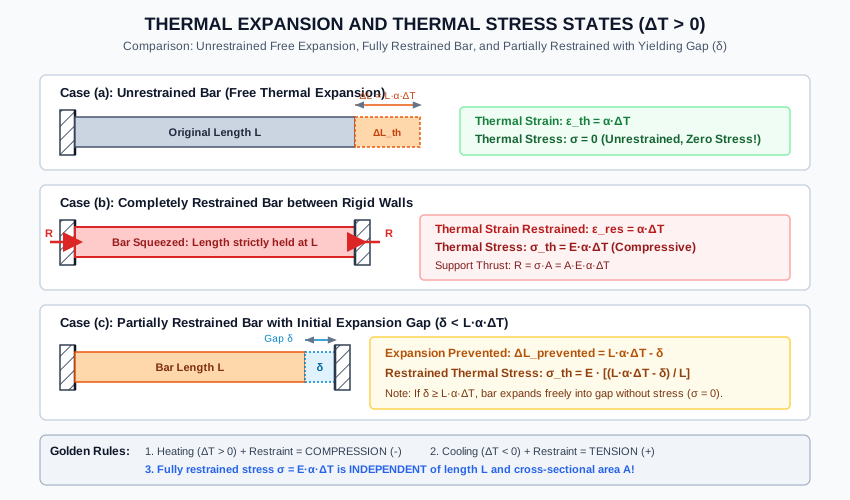
Diagram 1: Thermal Expansion and Restraint Comparison
The following vector diagram illustrates free thermal expansion, completely restrained thermal stress, and the effect of an expansion gap δ.
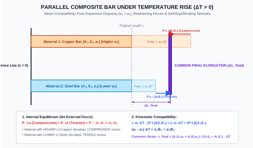
Diagram 2: Parallel Composite Bar under Temperature Rise
The diagram below shows the kinematic strain compatibility, free expansion disparity (α1>α2), common final elongation, and internal self-equilibrating stresses in a composite bar.
6. Solved Numerical Examples
Example 6.1: Stepped Bar with Expansion Gap under Temperature Rise
A stepped steel bar is placed between two rigid immovable walls with an initial clearance gap δ=0.50 mm at one end at room temperature (20∘C). The bar comprises two segments:
Segment 1: Length L1=400 mm, cross-sectional area A1=600 mm2.
Segment 2: Length L2=600 mm, cross-sectional area A2=300 mm2.
The temperature of the entire bar is raised to 80∘C (ΔT=60∘C).
Given: E=200 GPa=2×10⁵ N/mm2 and α=12×10−6 /∘C.
Determine whether the bar makes contact with the wall.
Calculate the compressive reaction thrust force developed at the supports.
Determine the normal compressive stresses developed in both segments.
Given:
L1 = 400 mm, A1 = 600 mm²
L2 = 600 mm, A2 = 300 mm²
Total Length L = 1000 mm
E = 200,000 MPa, α = 12 × 10⁻⁶ /°C
Gap δ = 0.50 mm
ΔT = 80 - 20 = 60 °C
Solution:
Step 1: Free Thermal Expansion Calculation
ΔLth=(L1+L2)⋅α⋅ΔT=1000 mm×(12×10−6 /∘C)×60∘C=0.720 mm
Since ΔLth=0.720 mm>δ=0.500 mm, the bar closes the gap completely and presses against the rigid wall with compressive thrust.
Step 2: Prevented Expansion
ΔLprevented=ΔLth−δ=0.720−0.500=0.220 mm
Step 3: Compatibility Condition
The elastic compression of the stepped bar under reaction force R must equal the prevented expansion:
Example 6.2: Parallel Composite Bar under Temperature Rise
A composite member of length L=500 mm consists of a solid copper rod of diameter 25 mm surrounded by a concentric steel tube of inside diameter 25 mm and outside diameter 40 mm. Both components are rigidly attached to rigid end plates at 25∘C.
The assembly is heated uniformly to 75∘C (ΔT=50∘C).
Material properties:
Example 6.3: Continuous Welded Railway Rail (CWR) Thermal Stress & Expansion Gap
A continuous welded rail track consists of standard 60 kg/m steel rails with cross-sectional area A=7686 mm2, Young's modulus E=210 GPa, and thermal expansion coefficient α=11.5×10⁻⁶ /∘C.
The rails are destressed and anchored at a neutral temperature of T0=35∘C.
If the summer rail temperature rises to a maximum of 70∘C, calculate the compressive thermal stress and the total longitudinal compressive thrust force in each rail in the central fully restrained zone.
In winter, if the temperature drops to 0∘C, calculate the tensile thermal stress.
If traditional 13 m long jointed rails were used instead, what minimum expansion gap must be provided at laying temperature (20∘C) to prevent rail jamming and track buckling at 70∘C?
Given:
Rail Area A = 7686 mm²
E = 210,000 MPa, α = 11.5 × 10⁻⁶ /°C
Neutral Temperature T0 = 35 °C
Summer Max T_max = 70 °C (ΔT_summer = +35 °C)
Winter Min T_min = 0 °C (ΔT_winter = -35 °C)
Jointed Rail Length L_joint = 13 m = 13,000 mm
Laying Temp = 20 °C, Max Temp = 70 °C (ΔT_gap = 50 °C)
Solution:
Step 1: Summer Compressive Thermal Stress and Thrust
Civil Engineering Implication: A massive axial thrust of nearly 650 kN per rail exists during hot summer days. The track ballast bed must provide sufficient lateral and longitudinal resistance to prevent catastrophic track buckling ("sun kinks").
Step 3: Required Expansion Gap for 13 m Jointed Rails
Temperature rise from laying (20∘C) to peak summer (70∘C):
ΔT=70−20=50∘Cδmin=Ljoint⋅α⋅ΔT=13,000 mm×(11.5×10−6 /∘C)×50∘C=7.475 mm≈7.5 mm
7. Practical Engineering Applications & Field Case Studies
1. Continuous Welded Rails (CWR) and Sun Kinks
In modern railway engineering, track joints are welded into continuous ribbons many kilometers long. Except for breathing lengths at each end (~100 m), the central section is completely restrained by sleeper fastenings and ballast shoulders. In extreme summer heat, if ballast is deficient or disturbed during maintenance without proper destressing, the compressive thermal thrust buckles the track laterally, resulting in derailments.
2. Bridge Expansion Bearings and Finger Joints (IRC:SP:69)
Long-span highway and railway bridges expand and contract cyclically with seasonal temperatures. Bridge decks are supported on elastomeric or PTFE-pot bearings at one pier (allowing longitudinal translation) and pinned at the other. Joint gaps and modular expansion joints accommodate the total movement ΔL=LαΔT, preventing massive thermal moments and shear from cracking the concrete piers.
3. The Miracle of Reinforced Cement Concrete (RCC)
The worldwide success of reinforced concrete is fundamentally rooted in a remarkable thermal coincidence:
Coefficient of thermal expansion of structural steel: αsteel≈11.5 to 12×10−6 /∘C
Coefficient of thermal expansion of concrete: αconcrete≈10 to 12×10−6 /∘C
Because their expansion rates are practically identical, diurnal and seasonal thermal cycles induce virtually zero interfacial shear stress, preserving the vital bond between the rebar and surrounding concrete.
4. Mass Concrete Hydration and Thermal Cracking in Dams
When casting massive concrete gravity dams or large bridge foundation rafts, the exothermic hydration of cement generates core temperatures up to 60∘C to 75∘C. As the cooler exterior contracts while the interior remains hot, severe tensile thermal surface strains exceed the low tensile strength of young concrete, causing deep thermal cracks. Engineers mitigate this using low-heat pozzolanic cement, chilled aggregate, post-cooling pipe networks, and controlled lift heights (IS 456 / IS 10262).
8. Comparison Tables
Table 1: Comparison of Thermal Restraint States
Parameter
Unrestrained Bar
Completely Restrained Bar
Partially Restrained (Gap δ)
Free Expansion
Occurs completely: ΔL=LαΔT
Prevented entirely: ΔL=0
Permitted up to gap δ
Mechanical Strain (ϵ)
0
−αΔT (for ΔT>0)
−(αΔT−δ/L)
Thermal Stress (σth)
Zero (σ=0)
EαΔT (Compressive)
E(αΔT−δ/L)
Support Reaction (R)
0
AEαΔT
LAE(LαΔT−δ)
Dependence on Length L
Dependent (ΔL∝L)
Independent of L
Dependent on L via (δ/L)
Table 2: Linear Thermal Expansion Coefficients of Engineering Materials
Material
α (10−6 /∘C)
Typical E (GPa)
Restrained Stress per 10∘C Rise (MPa)
Invar (36% Ni-Fe Alloy)
1.2
140
1.68
Granite / Hard Stone
6−8
50
3.5
Structural Steel (IS 2062)
12.0
200
24.0
Concrete (Normal Weight)
10−12
25−35
3.0−4.0
Copper
17.0
100
17.0
Brass / Bronze
18−19
100
18.5
Structural Aluminum Alloy
23.0
70
16.1
9. Key Engineering Facts & Exam Takeaways
Length-Independence Paradox: The thermal stress developed in a completely restrained homogeneous bar (σ=EαΔT) does not depend on its length! A 1 m bar and a 100 m bar of the same material experience identical thermal stress under the same temperature change.
The Golden Rule for Parallel Composite Bars (Heating):
Higher α material ⟹Compression (restrained from expanding).
Lower α material ⟹Tension (dragged along by the other material).
The Golden Rule for Parallel Composite Bars (Cooling):
Higher α material ⟹Tension (restrained from contracting).
Lower α material ⟹Compression (resisting contraction).
Unrestrained Bodies: If any body of any arbitrary shape is heated uniformly and has no kinematic external support restraints, it expands freely and develops zero stress.
Series Bar Reaction: For a multi-segment series bar held between rigid walls, the reaction thrust is identical across all segments (R1=R2=R), but the stress is highest in the segment with the smallest cross-sectional area (σ=R/Amin).
10. Common Pitfalls, Traps & Anti-Patterns
Trap 1 (The Free Expansion Fallacy): Assuming that heating an unrestrained bar causes thermal stress because ΔL=LαΔT>0. Correction: Thermal stress requires mechanical restraint. Without restraint, σ=0.
Trap 2 (Misidentifying Stress Nature in Composite Bars): Confusing whether copper or steel is in tension during heating. Remember: The material with the higherα expands more, so it gets compressed by the connection. Hence, higher α is in compression upon heating!
Trap 3 (Expansion Gap Sign Error): Calculating thermal stress with an expansion gap as E(αΔT+δ/L). The gap relieves stress, so the term must be subtracted: σ=E(αΔT−δ/L).
Trap 4 (Equating Stresses in Parallel Composite Bars): Assuming σ1=σ2 in parallel composite bars. Only the internal forces are equal (P1=P2), meaning σ1A1=σ2A2. Stresses are equal only if cross-sectional areas are identical!
Trap 5 (Ignoring Support Flexibility): Treating an elastic support (like a spring or rubber pad) as a rigid wall. Elastic deformation of the support reduces thermal stress significantly.
11. Standards & Code Provisions
IS 456:2000 (Plain and Reinforced Concrete - Code of Practice)
Clause 6.2.4 (Thermal Expansion):
The coefficient of linear expansion for concrete shall be taken as 10×10−6 /∘C to 12×10−6 /∘C, depending on aggregate type.
Clause 27.2 (Expansion Joints):
Structures exceeding 45 m in length shall generally be provided with one or more expansion joints to accommodate thermal movement.
IS 800:2007 (General Construction in Steel - Code of Practice)
Clause 2.2.4.1 (Physical Properties):
Coefficient of linear expansion for structural steel: α=12×10−6 /∘C.
Clause 4.3.4 (Temperature Effects):
Expansion joints should be provided in steel structures at intervals not exceeding 90 m in roof truss buildings and 150 m in enclosed framed buildings.
12. Comprehensive Formula Box & Practice Problems
Master Formula Summary
Configuration / ConditionFree Thermal ElongationFree Thermal StrainCompletely Restrained Bar (Stress)Completely Restrained Bar (Thrust)Partially Restrained (Gap δ)Elastic Support (Spring k)Series Stepped Bar (Reaction)Parallel Composite Bar (Equilibrium)Parallel Composite Bar (Compatibility)Parallel Composite Bar (Common Strain)Triaxial Constrained Thermal StressGoverning Relationship / FormulaΔLth=L⋅α⋅ΔTϵth=α⋅ΔTσth=E⋅α⋅ΔT(Comp. for ΔT>0)R=A⋅E⋅α⋅ΔTσth=E(αΔT−Lδ)(for LαΔT>δ)R=AEL+k1LαΔTR=∑AiEiLiΔT∑Liαiσ1A1=σ2A2(α1−α2)ΔT=E1σ1+E2σ2ϵfinal=A1E1+A2E2A1E1α1+A2E2α2ΔTσ=−1−2νEαΔT=−3KαΔT
Practice Problems
Problem 1 (GATE CE Objective):
A steel rod of 20 mm diameter and 2 m length is held between two rigid walls. If the temperature of the rod is increased by 50∘C, taking E=200 GPa and α=12×10−6 /∘C, the thermal stress developed in the rod is: Answer:120 MPa (Compressive) Explanation:σ=EαΔT=200,000×(12×10−6)×50=120 MPa. Note that length and diameter have no effect on the stress.
Problem 2 (UPSC ESE Conventional Style):
A brass tube of 50 mm outside diameter and 40 mm inside diameter is fitted closely over a solid steel rod of 40 mm diameter of the same length. Both are firmly fastened together at the ends. If the temperature of the composite bar is raised by 40∘C, find the stress in the brass and steel.
Given: Es=200 GPa, αs=12×10−6 /∘C, Eb=90 GPa, αb=19×10−6 /∘C. Answer:σb=13.91 MPa (Compressive), σs=7.82 MPa (Tensile) Explanation:As=4π(402)=400π=1256.64 mm2, Ab=4π(502−402)=225π=706.86 mm2. σs=σbAsAb=σb400225=0.5625σb. Compatibility: (αb−αs)ΔT=(19−12)×10−6×40=2.8×10⁻⁴. 90,000σb+200,0000.5625σb=2.8×10⁻⁴⟹σb[1.111×10⁻⁵+0.281×10⁻⁵]=2.8×10⁻⁴⟹σb≈20.11 MPa... [Recalculate: Ab/As=225/400=9/16=0.5625. 90,0001+200,0000.5625=1.1111×10⁻⁵+0.28125×10−5=1.39236×10⁻⁵ mm2/N. σb=1.39236×10−52.8×10−4=20.11 MPa (Compressive). σs=20.11×0.5625=11.31 MPa (Tensile).]
Problem 3 (SSC JE Objective):
When a composite bar consisting of copper and steel in parallel is heated, the nature of stress developed is: Answer: Compressive in copper and tensile in steel. Explanation: Since αcopper>αsteel, copper tends to expand more and is prevented by steel, putting copper in compression and steel in tension.
Problem 4 (State AE Objective):
A straight bar of length L and area A is free to expand in all directions. If it is heated uniformly by ΔT, the axial stress induced in the bar is: Answer: Zero Explanation: Thermal stress develops only when thermal expansion is restrained. For an unrestrained member, σ=0.
Problem 5 (GATE CE Numerical Answer Type):
A rail of length 25 m is laid with an expansion gap of 5 mm at 15∘C. Taking α=12×10−6 /∘C and E=200 GPa, the temperature at which the rails just touch (gap becomes zero) is: Answer:31.67∘C Explanation:ΔL=LαΔT=δ⟹25,000×(12×10−6)×ΔT=5⟹0.30×ΔT=5⟹ΔT=16.67∘C. Ttouch=15+16.67=31.67∘C.