Moment-Area Theorems (Mohr's Theorems) & Conjugate Beam Method
In this chapter (4 topics)
On this page
- 1. Topic Metadata & Scope
- 2. Physical Mechanics & Theoretical Foundation
- 2.1 The Geometric Revolution in Deflection Analysis
- 3. Mathematical Derivations: Mohr's First Theorem (Slope Theorem)
- 3.1 Differential Angle Between Adjacent Normals
- 3.2 Integration Between Points A and B
- 3.3 Formal Statement of Mohr's First Theorem
- 4. Mathematical Derivations: Mohr's Second Theorem (Deflection Theorem)
- 4.1 Concept of Tangential Deviation (tB/A)
- 4.2 Integration for Total Deviation
- 4.3 Formal Statement of Mohr's Second Theorem
- 4.4 The Critical Asymmetry: tB/A ≠ tA/B
- 5. Analysis of Non-Prismatic Beams with Stepped Flexural Rigidity
- 6. The Conjugate Beam Method (Mohr's Analogy)
- 6.1 Fundamental Mathematical Analogy
- 6.2 The Two Master Theorems of Conjugate Beam
- 6.3 Support Transformation Rules (Real longleftrightarrow Conjugate)
- 7. SVG Technical Diagrams & Visual Explanations
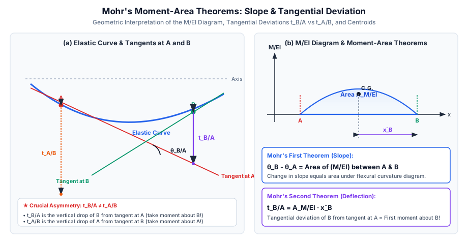
- 7.1 Mohr's Moment-Area Theorems & Tangential Deviations
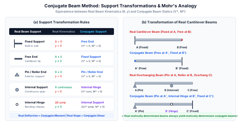
- 7.2 Conjugate Beam Support Transformation Analogy
- 8. Step-by-Step Solved Numerical Examples
- Problem 1: Non-Prismatic Stepped Cantilever Beam (GATE CE Pattern)
- Problem 2: Conjugate Beam Method for Overhanging Beam (UPSC ESE Pattern)
- Problem 3: Moment-Area for Symmetrical Circular Bending (State AE Pattern)
- 9. Comparative Analysis & Summary Matrix
- 10. Key Takeaways & Exam-Oriented Highlights
- 11. Common Traps, Pitfalls & Counter-Intuitive Exam Scenarios
- 12. Standard Code Provisions & Objective Practice Problems
- Reference Code Clauses
- Objective Practice Problems
1. Topic Metadata & Scope
| Attribute | Specification |
|---|---|
| Topic ID | SOM-07-03 |
| Chapter | Chapter 07: Deflection of Beams (07_deflection_of_beams) |
| Subject | Strength of Materials (Solid Mechanics) |
| Target Examinations | GATE CE, UPSC ESE, SSC JE, State AE, RRB JE |
| Prerequisites | SOM-07-01 (Differential Equation of Elastic Curve), SOM-03-03 (Bending Moment Diagrams), SOM-04-02 (Non-Prismatic Cross-Sections) |
| Authoritative Reference Codes | IS 456:2000 Cl. 23.2, IS 800:2007 Table 6, Eurocode 3 Part 1-1 |
| Key Terminology | Christian Otto Mohr, Moment-Area theorems, diagram, elastic curvature area, tangential deviation ( vs ), centroid location (), Conjugate Beam Method (Mohr's Analogy), elastic loading (), conjugate shear (), conjugate moment (), support transformation rules |
2. Physical Mechanics & Theoretical Foundation
2.1 The Geometric Revolution in Deflection Analysis
While the double integration and Macaulay methods approach beam deflections via differential equations, Christian Otto Mohr (1868) demonstrated that beam deflections and rotations can be computed purely through geometry and statics:
- Curvature as Distributed Elastic Weight: The term is the curvature of the beam.
- Deflection as Cumulative Curvature: Bending slope is the cumulative area of this curvature, and vertical displacement is the cumulative first moment of this curvature area.
- Power in Non-Prismatic Beams: In real bridge girders, stepped building columns, and flitched structural members where flexural rigidity changes abruptly, solving differential equations is algebraically painful due to varying . The Moment-Area method handles stepped with trivial geometric ease simply by dividing the local bending moment by the local value of .
3. Mathematical Derivations: Mohr's First Theorem (Slope Theorem)
3.1 Differential Angle Between Adjacent Normals
Consider an elemental length of a beam subjected to bending moment . The neutral axis bends into an arc of radius , subtending an angle :
From the Euler-Bernoulli flexure formula ():
3.2 Integration Between Points and
Integrating both sides between two points and along the beam axis:
3.3 Formal Statement of Mohr's First Theorem
Mohr's 1st Theorem: The change in slope (angle of rotation) between the tangents drawn to the elastic curve at any two points and is equal to the total area of the diagram between those two points.
- Sign Convention:
- Sagging (positive) bending moment creates positive area (tangent rotates counter-clockwise relative to tangent at ).
- Hogging (negative) bending moment creates negative area (tangent rotates clockwise).
4. Mathematical Derivations: Mohr's Second Theorem (Deflection Theorem)
4.1 Concept of Tangential Deviation ()
Draw a tangent to the elastic curve at point and extend it beneath point . The vertical distance from point on the elastic curve to this extended tangent line is called the tangential deviation of with respect to , denoted as .
For an elemental segment at distance from point :
- The elemental angle of bend is .
- Projecting this angle over the horizontal lever arm to point produces an elemental vertical intercept:
4.2 Integration for Total Deviation
Integrating from to :
By definition of the first moment of an area:
where:
- is the area of the diagram between sections and .
- is the horizontal distance from the centroid of this area to point (the point whose deviation is being measured).
4.3 Formal Statement of Mohr's Second Theorem
Mohr's 2nd Theorem: The tangential deviation of a point on the elastic curve with respect to the tangent drawn at point is equal to the first moment of the diagram area between and , taken about point .
4.4 The Critical Asymmetry:
One of the most frequent errors in competitive examinations is confusing with :
- : Vertical distance of point from the tangent at . Moment is taken about ().
- : Vertical distance of point from the tangent at . Moment is taken about ().
- In general:
5. Analysis of Non-Prismatic Beams with Stepped Flexural Rigidity
When a beam has a sudden step-change in cross-section (e.g., from to ):
- The bending moment remains continuous across the step (unless an external couple acts there).
- The diagram exhibits an immediate step-jump:
- The area of the diagram is computed by dividing it into standard geometric sub-areas (rectangles, triangles, parabolas) on each side of the step, and applying Mohr's theorems directly without any differential equation matching!
6. The Conjugate Beam Method (Mohr's Analogy)
6.1 Fundamental Mathematical Analogy
Consider the two pairs of differential equations:
Notice the mathematical identity:
- If we construct an imaginary, fictitious beam (called the Conjugate Beam) of the same span length as the real beam, and load it with an elastic distributed load :
- The internal Shear Force in the conjugate beam is governed by , which is mathematically identical to !
- The internal Bending Moment in the conjugate beam is governed by , which is mathematically identical to !
6.2 The Two Master Theorems of Conjugate Beam
6.3 Support Transformation Rules (Real Conjugate)
To ensure the conjugate beam reproduces the exact slope and deflection boundary conditions of the real beam, its supports must be transformed:
  ┌────────────────────────────────┬──────────────────────────────────┬─────────────────────────────────┐
  │ Real Beam Support Condition    │ Real Kinematic State             │ Conjugate Beam Support Required │
  ├────────────────────────────────┼──────────────────────────────────┼─────────────────────────────────┤
  │ Fixed Support (Built-in)       │ Deflection y = 0, Slope θ = 0    │ Free End (M* = 0, V* = 0)       │
  ├────────────────────────────────┼──────────────────────────────────┼─────────────────────────────────┤
  │ Free End (Cantilever tip)      │ Deflection y ≠ 0, Slope θ ≠ 0    │ Fixed Support (M* ≠ 0, V* ≠ 0)  │
  ├────────────────────────────────┼──────────────────────────────────┼─────────────────────────────────┤
  │ Pinned / Roller at End         │ Deflection y = 0, Slope θ ≠ 0    │ Pinned / Roller at End          │
  ├────────────────────────────────┼──────────────────────────────────┼─────────────────────────────────┤
  │ Internal Continuous Roller     │ Deflection y = 0, θ continuous   │ Internal Hinge (M* = 0, V* cont)│
  ├────────────────────────────────┼──────────────────────────────────┼─────────────────────────────────┤
  │ Internal Hinge                 │ Deflection y ≠ 0, Δθ jump        │ Internal Roller (M* ≠ 0, ΔV*)   │
  └────────────────────────────────┴──────────────────────────────────┴─────────────────────────────────┘
[!TIP] A statically determinate real beam always transforms into a statically determinate conjugate beam! For example, a real cantilever (fixed at , free at ) becomes a conjugate cantilever (free at , fixed at ).
7. SVG Technical Diagrams & Visual Explanations
7.1 Mohr's Moment-Area Theorems & Tangential Deviations
The diagram below details the elastic curve, tangents, subtended rotation , tangential deviations vs , and the centroidal projection of the diagram:
7.2 Conjugate Beam Support Transformation Analogy
The diagram below presents the transformation matrix between real beam boundary conditions and their conjugate beam counterparts, featuring worked structural layouts:
8. Step-by-Step Solved Numerical Examples
Problem 1: Non-Prismatic Stepped Cantilever Beam (GATE CE Pattern)
Statement:
A non-prismatic cantilever beam of total span is rigidly built-in at () and carries a concentrated vertical load at its free tip (). The flexural rigidity of the beam is stepped:
- Fixed end to midspan (): Flexural rigidity is ().
- Midspan to free tip (): Flexural rigidity is ().
Using Mohr's Moment-Area theorems, determine:
- The slope at the free tip ().
- The vertical deflection at the free tip ().
Solution:
Step 1: Bending Moment Values
Taking coordinate measuring from free tip () towards fixed end ():
- At free tip ():
- At junction ():
- At fixed wall ():
Step 2: Construct the Diagram
-
Right Segment ( to , rigidity ):
- At :
- At (right side):
- Shape is a triangle of base and height :
- Centroid of from tip :
-
Left Segment ( to , rigidity ):
- At (left side):
- At :
- Shape is a trapezoid of length , which we divide into a rectangle and a triangle:
- Rectangle Area ():
- Triangle Area ():
Step 3: Tip Slope via Mohr's First Theorem
Because the beam is built-in at , the tangent at is horizontal ():
Step 4: Tip Deflection via Mohr's Second Theorem
Since the tangent at is horizontal, the vertical deflection at is identical to the tangential deviation :
Substituting :
Problem 2: Conjugate Beam Method for Overhanging Beam (UPSC ESE Pattern)
Statement:
A beam has a main span supported on a pin at and a roller at , with an overhanging span . A concentrated load acts downwards at the overhanging tip . Flexural rigidity is constant.
Using the Conjugate Beam Method:
- Construct the conjugate beam including its transformed supports.
- Determine the slope at the left support ().
- Compute the vertical deflection at the overhanging tip ().
Solution:
Step 1: Real Beam Statics
- Taking moments about :
- Equilibrium in :
- Bending Moment Diagram:
- At :
- At : (Hogging)
- At :
- The BMD is triangular over and triangular over , with a peak hogging moment of at support .
Step 2: Formulate the Conjugate Beam
- Support Transformations:
- Real Support (End Pin) Conjugate Support remains a Pin Support.
- Real Support (Internal Continuous Roller) Conjugate Support transforms into an Internal Hinge!
- Real Tip (Free End) Conjugate Tip transforms into a Fixed Support!
- Conjugate Loading:
- Because real moment is negative (hogging), the elastic load acts downwards:
- Segment (): Triangular downward load from at to at .
- Segment (): Triangular downward load from at to at .
- Because real moment is negative (hogging), the elastic load acts downwards:
Step 3: Slope at Real Support
The slope in the real beam equals the shear force in the conjugate beam:
- In the conjugate beam, hinge transmits zero bending moment ( for span ):
Step 4: Deflection at Overhanging Tip
The vertical deflection in the real beam equals the bending moment at fixed support of the conjugate beam:
- Shear transmitted across internal hinge from span : Therefore, an upward shear force of acts on segment at hinge (downward reaction on segment ).
- Taking moments about fixed support for cantilever :
Substituting :
Problem 3: Moment-Area for Symmetrical Circular Bending (State AE Pattern)
Statement:
A simply supported beam of span is subjected to equal and opposite clockwise and counter-clockwise couples at its left and right ends, inducing pure sagging bending across the whole span. Given flexural rigidity , determine:
- The end rotation using Mohr's 1st Theorem.
- The central deflection using Mohr's 2nd Theorem.
Solution:
Step 1: Geometry of the Diagram
Under equal end couples, the bending moment is constant: .
- The diagram is a perfect rectangle of length and height .
- By symmetry, the slope at midspan is zero: .
Step 2: End Slope via Mohr's 1st Theorem
Applying Mohr's 1st theorem between support and midspan ():
Step 3: Central Deflection via Mohr's 2nd Theorem
Because the tangent at midspan is perfectly horizontal, the vertical deflection at midspan equals the tangential deviation of support from the midspan tangent:
Here, the area between and is a rectangle of width :
The centroid of this rectangle from support is:
9. Comparative Analysis & Summary Matrix
| Attribute / Parameter | Mohr's Moment-Area Method | Conjugate Beam Method | Macaulay's Method |
|---|---|---|---|
| Originator & Year | Christian Otto Mohr (1868) | Christian Otto Mohr (1868) | W. H. Macaulay (1919) |
| Mathematical Basis | Geometric integration of | Static equilibrium of fictitious beam | Singularity step functions |
| Calculates Directly | Relative slope & deviation | Absolute slope () & deflection () | Closed-form continuous equation |
| Non-Prismatic Stepped Beams | Extremely Simple (step areas) | Very Simple (stepped loading) | Difficult (requires variable coefficient ODE) |
| Overhanging Beams | Requires careful geometric sketching | Superior (internal hinge at support) | Simple via continuation trick |
| Statically Indeterminate Beams | Used for prop reactions via compatibility | Conjugate beam becomes unstable/determinate | Used with redundant prop reactions |
10. Key Takeaways & Exam-Oriented Highlights
- Mohr's 1st Theorem: diagram between and .
- Mohr's 2nd Theorem: (first moment of area taken about point ).
- Cantilever Trick: Since a fixed support has and the tangent is horizontal, and .
- Simply Supported Midspan Trick: For symmetric beams, , so , and .
- Conjugate Beam Twin Identities:
- Support Inversion: Fixed becomes Free; Free becomes Fixed; Internal Support becomes Internal Hinge.
11. Common Traps, Pitfalls & Counter-Intuitive Exam Scenarios
- Trap 1: Centroid Distance to Wrong Point in Mohr's 2nd Theorem:
Misconception: Calculating by taking the centroid distance to instead of .
Correction: In , the deviation is measured at point , so moments must be taken about point (). Taking moments about gives , which is completely different! - Trap 2: Assuming Equals Deflection in Simply Supported Beams:
Misconception: Thinking for a simply supported beam.
Correction: At support , deflection is zero (). is only the vertical distance between the support and the tangent drawn at . The deflection at any interior point requires geometric proportions: . - Trap 3: Forgetting to Divide Moment by in Non-Prismatic Beams:
Misconception: Using the raw bending moment area and dividing by an average .
Correction: In stepped beams, each segment's area must be divided by its own specific value (). - Trap 4: Conjugate Beam Internal Hinge vs Internal Support:
Misconception: Replacing a real internal hinge with an internal hinge in the conjugate beam.
Correction: A real internal hinge allows a slope discontinuity () with continuous deflection, which corresponds to a shear step () with continuous moment in the conjugate beam—meaning it must be replaced by an internal roller support!
12. Standard Code Provisions & Objective Practice Problems
Reference Code Clauses
- IS 456:2000 Cl. 23.2 & IS 800:2007 Table 6:
Permissible deflection limits require verified structural calculations. Moment-area and conjugate beam methods are recognized by standard design offices as the primary hand-calculation tools for checking serviceability deflections in non-prismatic girders and bridge superstructures.
Objective Practice Problems
Problem 1 (GATE CE)
A cantilever beam of length has flexural rigidity for the left half () and flexural rigidity for the right half (). A concentrated moment acts at the free tip (). The rotation at the free tip is:
- (A)
- (B)
- (C)
- (D)
Answer: (B)
Solution:
Bending moment is uniform across the whole span: .
The diagram consists of two rectangles:
Left half ( to ): Height , Area .
Right half ( to ): Height , Area .
By Mohr's 1st Theorem, tip slope .
Problem 2 (UPSC ESE)
In the Conjugate Beam Method, an internal hinge in the real beam transforms into:
- (A) A free end in the conjugate beam
- (B) An internal roller support in the conjugate beam
- (C) A fixed support in the conjugate beam
- (D) An internal hinge in the conjugate beam
Answer: (B)
Solution:
In a real beam, an internal hinge allows a slope discontinuity () while maintaining zero bending moment and non-zero continuous deflection (). In the conjugate beam, this requires an internal support where shear has a step discontinuity () and bending moment is continuous non-zero.
Problem 3 (SSC JE / RRB JE)
According to Mohr's Second Theorem, the tangential deviation of point on the elastic curve from the tangent drawn at point () is:
- (A) The area of the diagram between and
- (B) The moment of the diagram area between and about point
- (C) The moment of the diagram area between and about point
- (D) The product of slopes at and
Answer: (C)
Solution:
, which is the first moment of the area taken about the point being measured (point ).
Problem 4 (GATE CE)
A cantilever beam of span is subjected to a uniformly distributed load over its entire length. The deflection of the free end is . If the flexural rigidity of the beam is doubled (), the new deflection will be:
- (A)
- (B)
- (C)
- (D)
Answer: (B)
Solution:
. Doubling halves the deflection ().
Problem 5 (State AE / ESE)
The conjugate beam of a real beam that is simply supported at both ends is:
- (A) Fixed at both ends
- (B) Cantilever beam
- (C) Simply supported at both ends
- (D) Free at both ends
Answer: (C)
Solution:
At exterior pin and roller supports, real deflection () and slope (). The conjugate boundary condition that has zero bending moment and non-zero shear force is also a pin or roller support. Hence, a simply supported real beam transforms into a simply supported conjugate beam!