Transformation of Plane Stress & Stresses on Oblique Planes
In this chapter (5 topics)
On this page
- 1. Metadata & Syllabus Mapping
- Official Examination Syllabus Mapping
- 2. Introduction & Physical Mechanics
- The Concept of Plane Stress
- Why Oblique Plane Analysis is Critical in Engineering
- 3. Mathematical Formulations & Derivations
- 3.1 Equilibrium of an Oblique Triangular Wedge Element
- 3.2 Derivation of Normal Stress (σθ)
- 3.3 Derivation of Tangential Shear Stress (τθ)
- 3.4 Stresses on Perpendicular Plane (θ + 90°) & The First Stress Invariant (I1)
- 💎 The First Stress Invariant Theorem
- 3.5 Important Canonical Special Cases
- 4. Engineering Assumptions & Limitations
- 5. Technical Diagrams
- Diagram 1: Equilibrium of Oblique Wedge Element
- Diagram 2: Plane Stress Transformation via Coordinate Rotation
- 6. Solved Numerical Examples
- Example 1.1: General Biaxial Stress State with In-Plane Shear
- Example 1.2: Stresses on a Spiral Welded Pressure Vessel Seam
- Example 1.3: Reverse Stress Determination from Oblique Measurements
- 7. Practical Engineering Applications & Field Case Studies
- 1. Spiral Welded Steel Penstocks and Piles (IS 3589 / IS 2825)
- 2. Scarf and Finger Joints in Structural Timber (IS 883:1994)
- 3. Lüders Lines in Civil Structural Steel (IS 2062)
- 8. Comparison Tables
- Table 1: Summary of Stresses on Oblique Planes for Canonical Stress States
- Table 2: Plane Stress vs. Plane Strain Comparison
- 9. Key Engineering Facts & Exam Takeaways
- 10. Common Pitfalls, Traps & Anti-Patterns
- 11. Standards & Code Provisions
- IS 800:2007 (General Construction in Steel - Code of Practice)
- IS 2825 (Code for Unfired Pressure Vessels)
- 12. Comprehensive Formula Box & Practice Problems
- Master Formula Summary
- Practice Problems
1. Metadata & Syllabus Mapping
| Attribute | Specification |
|---|---|
| Topic ID | SOM-02-01 |
| Module / Subject | Subject 02: Strength of Materials (notes/strength_of_materials/) |
| Chapter | Chapter 02: Principal Stresses and Strains (02_principal_stresses_and_strains) |
| Target Examinations | GATE CE, UPSC ESE, SSC JE, RRB JE, State AE, State JE |
| Prerequisites | SOM-01-01 (Stress and Strain), SOM-01-03 (Elastic Constants) |
| Primary Code References | IS 800:2007 (Steel Design - Combined Stresses & Welds), IS 2825 (Unfired Pressure Vessels) |
| Verification Gate | Level 1 through Level 7 Quality Standards |
Official Examination Syllabus Mapping
Website note: this mapping is from the author’s notes. It has not been checked against the official notification for each examination; confirm the current syllabus with the examining body.
- GATE Civil Engineering: Solid Mechanics — Transformation of plane stress; stresses on inclined/oblique planes; stress invariants; pure shear transformation.
- UPSC ESE (Engineering Services): Paper-I Building Materials and Structural Analysis — Analysis of state of stress; Cauchy stress formulas; transformation of components under rotation of axes.
- SSC JE / RRB JE / State AE: Normal and tangential stresses on oblique sections; maximum shear stress planes in uniaxial tension; complementary shear stresses.
2. Introduction & Physical Mechanics
In civil engineering structures, structural members are rarely subjected to pure unidirectional tension or compression. Beams under bending experience simultaneous longitudinal normal stresses and transverse shear stresses; shafts transmit torque causing shear; and thin-walled cylindrical pipes and pressure vessels experience biaxial normal hoop and longitudinal stresses.
The Concept of Plane Stress
A solid body is in a state of Plane Stress in the -plane if the stress components perpendicular to that plane are identically zero:
Thus, the state of stress at any point is completely characterized by just three independent components:
- Normal stress along the -axis:
- Normal stress along the -axis:
- In-plane shear stress: (with by moment equilibrium)
Why Oblique Plane Analysis is Critical in Engineering
Although internal stresses are originally computed on Cartesian reference planes ( and ), materials do not necessarily fail along the coordinate axes:
- Ductile materials (e.g., structural mild steel) fail primarily by shear slip along planes experiencing maximum shear stress (e.g., at to the tensile axis).
- Brittle materials (e.g., concrete, cast iron, masonry) fail by cleavage along planes experiencing maximum principal tensile stress.
- Fabricated connections (such as spiral welded steel pipes or glued timber scarf joints) have oriented planes of relative weakness that do not align with the global axes.
Therefore, determining the normal stress () and tangential shear stress () acting across an arbitrary plane inclined at an angle is fundamental to structural design.
3. Mathematical Formulations & Derivations
3.1 Equilibrium of an Oblique Triangular Wedge Element
Consider an infinitesimal right-triangular wedge cut from a body in plane stress:
              A (Top vertex)
             /|
            / |  Vertical face: area dAx = dA · cos θ
           /  |  Stresses: σx (normal), τxy (shear)
          /   |
         /    |
        /     |
       /______| B (Right-angle vertex)
      C
     Horizontal face: area dAy = dA · sin θ
     Stresses: σy (normal), τxy (shear)

     Oblique Hypotenuse Face AC:
     Area = dA
     Angle θ: measured counterclockwise from the vertical plane AB to the cut AC
     Normal vector n: makes angle θ with the positive x-axis
     Tangential vector t: parallel to the cut plane AC
Step 1: Area Relations
Let the area of the inclined oblique face be . From simple trigonometry:
- Area of the vertical face (normal in direction):
- Area of the horizontal face (normal in direction):
Step 2: Surface Forces Acting on Wedge Faces
Force is stress multiplied by cross-sectional area:
- On vertical face ():
- Normal force in direction:
- Shear force in direction:
- On horizontal face ():
- Normal force in direction:
- Shear force in direction:
- On oblique face ():
- Normal force along normal axis :
- Tangential force along tangential axis :
3.2 Derivation of Normal Stress ()
Summing all forces acting on the wedge along the outward normal direction ():
Substitute the force expressions:
Cancel throughout:
Using trigonometric double-angle identities:
Rearranging into average stress and deviatoric stress terms:
3.3 Derivation of Tangential Shear Stress ()
Summing forces along the tangential direction (), taking positive in the direction of increasing :
Substitute forces:
Cancel throughout:
Using identities and :
3.4 Stresses on Perpendicular Plane () & The First Stress Invariant ()
Consider the plane mutually perpendicular to the oblique cut, oriented at :
Substituting into Eq. (1.4):
Now, add Eq. (1.4) and Eq. (1.7):
💎 The First Stress Invariant Theorem
For any state of plane stress, the sum of normal stresses on any two mutually perpendicular planes is a constant, independent of the orientation angle :
Furthermore, substituting into the shear stress equation Eq. (1.6):
This confirms the complementary nature of shear stresses on perpendicular planes.
3.5 Important Canonical Special Cases
Case I: Pure Uniaxial Tension ()
- At (vertical plane): , .
- At (horizontal plane): , .
- At :
Physical Engineering Fact: In a standard tensile test of mild steel, the maximum shear stress develops on planes inclined at to the tensile load axis. Since ductile metals yield by slip of atomic planes along maximum shear planes, yielding begins along visible bands (Lüders Bands), resulting in the classic Cup-and-Cone ductile fracture.
Case II: Biaxial Hydrostatic / Equal Tension ()
Observation: When normal stresses in two perpendicular directions are equal and shear is zero, every plane is subjected to the same normal stress and zero shear stress! The state of stress is completely isotropic in-plane.
Case III: Pure Shear ()
- At : (Maximum tensile normal stress), .
- At (or ): (Maximum compressive normal stress), .
Physical Engineering Fact: Pure shear is completely equivalent to equal biaxial tension and compression acting at ! When a piece of brittle chalk or a cast-iron circular bar is twisted to failure in torsion (pure shear), it fractures along a crisp helical surface because brittle materials are weakest in tension.
4. Engineering Assumptions & Limitations
- Continuum Element: The triangular wedge is differential (), ensuring stress gradients across the face vanish and the stress state is homogeneous throughout the wedge.
- Plane Stress State: The through-thickness stress and out-of-plane shear stresses are zero. This strictly holds for thin plates, sheets, and thin-walled hollow shells without out-of-plane surface traction.
- Equilibrium in Undeformed State: Displacements and rotations under load are small such that the geometry of the triangle does not distort significantly prior to equilibrium analysis.
- Sign Convention Consistency: The derivation assumes is measured counterclockwise from the vertical plane (). If an examination problem defines from the horizontal plane or longitudinal axis, must be replaced by .
5. Technical Diagrams
Diagram 1: Equilibrium of Oblique Wedge Element
The following vector diagram details the wedge geometry, differential area components, and force equilibrium along normal () and tangential () axes.
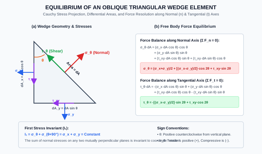
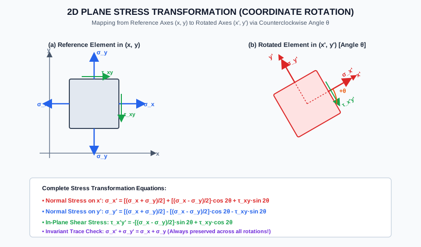
Diagram 2: Plane Stress Transformation via Coordinate Rotation
The diagram below shows the transformation from reference axes to rotated axes by counterclockwise angle , illustrating the stress components and the invariant trace property.
6. Solved Numerical Examples
Example 1.1: General Biaxial Stress State with In-Plane Shear
At a critical point in a structural steel web of an I-girder, the state of plane stress consists of:
- Tensile stress along horizontal axis:
- Compressive stress along vertical axis:
- Shear stress:
Determine:
- The normal and shear stresses acting on an oblique plane inclined at counterclockwise to the vertical plane.
- The normal stress on the plane perpendicular to the oblique plane ().
- Verify the First Stress Invariant ().
Given:
σx = +100 MPa
σy = -40 MPa
τxy = +40 MPa
θ = 30° (counterclockwise from vertical plane) ==> 2θ = 60°
Solution:
Step 1: Compute Average and Half-Difference Stresses
Step 2: Trigonometric Terms for
Step 3: Normal Stress on Oblique Plane ()
Step 4: Shear Stress on Oblique Plane ()
(The negative sign indicates the shear stress acts opposite to the positive tangential direction .)
Step 5: Normal Stress on Perpendicular Plane ()
Step 6: Invariant Verification
Example 1.2: Stresses on a Spiral Welded Pressure Vessel Seam
A thin-walled cylindrical penstock of diameter is fabricated from steel plate by welding along a spiral seam. Under service internal water pressure:
- Circumferential hoop stress: (Tension)
- Longitudinal axial stress: (Tension)
- Shear stress on axial/circumferential planes:
The spiral weld seam makes an angle with the transverse (vertical) section of the cylinder.
Calculate the normal stress and shear stress acting across the weld seam.
Given:
σx = 60 MPa (longitudinal)
σy = 120 MPa (circumferential)
τxy = 0
θ = 25° ==> 2θ = 50°
Solution:
Step 1: Stresses and Trigonometry
Step 2: Normal Stress on the Weld Seam ()
Step 3: Shear Stress on the Weld Seam ()
Civil Engineering Insight: Notice that the normal tensile stress acting across the spiral weld () is 41% lower than the maximum hoop stress () that would act across a straight longitudinal weld! This is precisely why high-pressure penstocks, spiral piles, and gas pipelines are manufactured using helical/spiral welding.
Example 1.3: Reverse Stress Determination from Oblique Measurements
During field strain gauge monitoring of a bridge gusset plate:
- On the vertical plane (): Normal stress is and shear stress is .
- On a plane inclined at counterclockwise to the vertical plane, the normal stress is measured as .
Determine:
- The normal stress acting on the horizontal plane ().
- The shear stress acting on the plane.
Given:
σx = 80 MPa
τxy = 30 MPa
σ_45° = 90 MPa at θ = 45°
Solution:
Step 1: Apply Transformation Equation at
For , :
Substitute into Eq. (1.4):
Step 2: Solve for
Step 3: Shear Stress on Plane ()
7. Practical Engineering Applications & Field Case Studies
1. Spiral Welded Steel Penstocks and Piles (IS 3589 / IS 2825)
In water supply mains and hydroelectric penstocks, the internal fluid pressure produces hoop stress and longitudinal stress . If a longitudinal straight seam weld were used, the weld would have to carry 100% of the peak hoop stress . By winding the steel plate into a spiral at an angle , the normal stress on the weld seam drops to , significantly reducing the risk of catastrophic seam split.
2. Scarf and Finger Joints in Structural Timber (IS 883:1994)
Wood has high tensile strength parallel to the grain () but very low shear strength () and negligible tensile strength perpendicular to grain. When splicing timber beams, butt joints fail. Engineers use inclined scarf joints inclined at slope or (). The transformation equations ensure that the normal tensile stress perpendicular to the glue line and shear along the glue line remain well below adhesive capacities.
3. Lüders Lines in Civil Structural Steel (IS 2062)
When structural steel yield plates undergo monotonic tension, diagonal striations appear on the mill scale at an angle of roughly to the load axis. This is a direct physical manifestation of Eq. (1.12): occurs at . Because iron crystal lattices slip through dislocation movement on planes of maximum shear, yield initiation always follows these paths.
8. Comparison Tables
Table 1: Summary of Stresses on Oblique Planes for Canonical Stress States
| Stress State | Given Stresses | Normal Stress | Shear Stress | Maximum Shear |
|---|---|---|---|---|
| Uniaxial Tension | at | |||
| Uniaxial Compression | at | |||
| Pure Shear | at | |||
| Equal Biaxial Tension | (Constant) | (Zero everywhere) | Zero on all planes | |
| Equal & Opposite Biaxial | at |
Table 2: Plane Stress vs. Plane Strain Comparison
| Feature | Plane Stress State () | Plane Strain State () |
|---|---|---|
| Physical Geometry | Thin plates, thin shells, web plates | Thick bodies, long retaining walls, gravity dams, tunnels |
| Out-of-Plane Stress | ||
| Out-of-Plane Strain | ||
| Stress Transformation | Identical in-plane formulas apply | Identical in-plane formulas apply |
9. Key Engineering Facts & Exam Takeaways
- Sum of Normal Stresses is Constant: On any two planes at to each other, . If you know , and , you can immediately find without using trigonometry!
- Pure Shear on Planes: In pure uniaxial tension , the shear stress on the plane is , and the normal stress on that same plane is also .
- Pure Shear Principal Tension: In a state of pure shear , the maximum tensile normal stress is equal to and occurs at .
- Isotropic State: For and , shear stress is zero on all planes. Mohr's circle degenerates into a single point on the -axis.
- Angle Doubling: In all transformation equations, the physical angle appears doubled as . A rotation of in real physical space corresponds to in the equations.
10. Common Pitfalls, Traps & Anti-Patterns
- Trap 1 (Reference Plane Angle Confusion): Measuring from the horizontal axis instead of the vertical plane. If an exam problem states: "a plane inclined at to the horizontal", then its angle with the vertical is ! Always sketch the wedge normal.
- Trap 2 (Sign of Shear Stress ): Forgetting the negative sign in the first term of .
- Trap 3 (Sign of Given ): When is compressive, substituting a positive value. If , then , which turns into !
- Trap 4 (Confusing Stress with Force on Oblique Plane): Adding stresses directly instead of multiplying by area components (). Stresses are tensor quantities and cannot be resolved as vector forces without accounting for differential face areas.
11. Standards & Code Provisions
IS 800:2007 (General Construction in Steel - Code of Practice)
- Clause 10.5.10 (Combined Stresses in Welds):
Where butt or fillet welds are subject to combined normal stress () and shear stress (), the equivalent equivalent stress shall not exceed the design strength: - Clause 10.5.7 (Design of Oblique Fillet Welds):
Fillet welds loaded obliquely to their longitudinal axis must be proportioned using the effective throat area and resolved vector components.
IS 2825 (Code for Unfired Pressure Vessels)
- Allows a reduced joint efficiency factor () for spiral submerged-arc welded seams compared to longitudinal seams (), exploiting the lower normal stress on the inclined weld seam.
12. Comprehensive Formula Box & Practice Problems
Master Formula Summary
Practice Problems
-
Problem 1 (GATE CE Objective):
A prismatic bar is subjected to pure uniaxial tensile stress . The plane across which the normal stress and shear stress are equal in magnitude is inclined to the tensile axis at an angle of:
Answer:
Explanation: and . Equating: . -
Problem 2 (SSC JE Objective):
At a point in a strained material, the normal stresses on two mutually perpendicular planes are (tensile) and (compressive). What is the sum of normal stresses on any other pair of mutually perpendicular planes?
Answer:
Explanation: By the first stress invariant . -
Problem 3 (UPSC ESE Style):
A state of pure shear stress acts on an element. The normal stress on a plane inclined at to the shear plane is:
Answer: (Tensile)
Explanation: . -
Problem 4 (State AE Objective):
A wooden tie member is spliced using a glued scarf joint inclined at to the longitudinal axis. If the member carries a tensile stress of , the shear stress acting along the glue line is:
Answer:
Explanation: Angle of cut to the vertical cross section is . . -
Problem 5 (GATE CE Numerical Answer Type):
In a plane stress problem, , , and . The normal stress on a plane inclined at counterclockwise to the vertical plane is .
Answer:
Explanation: .