Losses of Prestress
In this chapter (4 topics)
On this page
- 1. Introduction & Classification of Prestress Losses
- 2. Loss Due to Elastic Shortening of Concrete
- 2.1 Pre-Tensioned Members
- 2.2 Post-Tensioned Members
- 3. Loss Due to Creep of Concrete
- 3.1 Creep Coefficient Method (IS 1343:2012 Cl. 6.2.5)
- 3.2 Specific Creep Strain Method
- 4. Loss Due to Drying Shrinkage of Concrete
- 4.1 Shrinkage Strain Formulation (IS 1343:2012 Cl. 6.2.4)
- 5. Loss Due to Relaxation of Steel
- 5.1 Factors Influencing Relaxation
- 5.2 Code Provisions (IS 1343:2012 Table 4)
- 6. Loss Due to Friction (Post-Tensioned Members Only)
- 6.1 Components of Friction
- 6.2 Governing Differential Formulation
- 6.3 Angular Change for Parabolic Tendons
- 6.4 Jacking Methods: One-End vs Both-Ends Jacking
- 7. Loss Due to Anchorage Slip (Post-Tensioned Members Only)
- 7.1 Uniform Anchorage Slip Formulation
- 7.2 The Inverse Length Law
- 8. Worked Numerical Examples with Complete Step-by-Step Verification
- Problem 1: Pre-Tensioned Beam Comprehensive Loss Estimation
- Problem 2: Post-Tensioned Cable Friction & Anchorage Slip Verification
- Problem 3: Sequential vs Simultaneous Tensioning in Multi-Tendon Girders
- 9. Comparative Technical Summary: Loss Allocation
- 10. Construction Practices & Site Pitfalls
- 11. Competitive Examination Traps & Problem-Solving Shortcuts
- 12. Practice Problems & Examination Review Exercises
- Level 1: Objective Conceptual (SSC JE / RRB JE)
- Level 2: Multi-Concept Analytical (GATE CE)
- Level 3: Conventional Design Problem (UPSC ESE Mains)
- 13. Complete Topic Architecture & Upstream/Downstream Dependencies
- 14. Verification & Standards References
1. Introduction & Classification of Prestress Losses
In prestressed concrete design, the initial jacking force () applied by the hydraulic jack is never permanently retained by the structural member. From the instant of prestress transfer through the entire service life of the structure, the prestressing force diminishes continuously due to a combination of instantaneous elastic deformations, mechanical anchorage movements, and long-term rheological properties of concrete and steel.
                           TAXONOMY OF PRESTRESS LOSSES
                                        │
         ┌──────────────────────────────┴──────────────────────────────┐
         ▼                                                             ▼
   IMMEDIATE LOSSES                                           TIME-DEPENDENT LOSSES
   (Occur at transfer / jacking)                             (Develop gradually over months/years)
         │                                                             │
         ├──────────────────────────────┐                              ├──────────────────────────────┐
         ▼                              ▼                              ▼                              ▼
   Elastic Shortening              Friction                       Creep of Concrete             Relaxation of Steel
   • Pre-tensioned: Full           • Post-tensioned only          • Sustained fc                • Constant strain
   • Post-tensioned: Sequential    • Curvature (μ·α)              • θ = 1.6 @ 28d               • 1.5% to 8% loss
     or zero if simultaneous         + Wobble (k·x)               • Δfs = θ·m·fc
                                        │                                                             │
                                        ▼                                                             ▼
                                 Anchorage Slip                                                Drying Shrinkage
                                 • Post-tensioned only                                         • Pre: εcs = 0.00030
                                 • Wedge draw-in (Δ/L)                                         • Post: 0.0002/log(t+2)
Accurate estimation of prestress loss is vital for structural safety and serviceability:
- Underestimating losses leads to unexpected tensile cracking, excessive sagging deflections, and potential fatigue failure under service loads.
- Overestimating losses results in excessive upward camber, unnecessary steel consumption, and high compressive stresses causing top fiber crushing at transfer.
2. Loss Due to Elastic Shortening of Concrete
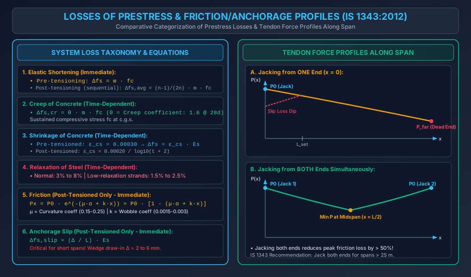
When the prestress force is transferred to the concrete, the concrete compresses and shortens elastically. Because bonded steel must shorten by the identical strain, it suffers an immediate drop in tensile stress.
2.1 Pre-Tensioned Members
In pre-tensioning, tendons are tensioned against external abutments before casting. When the tendons are severed at transfer, the concrete shortens instantly under the applied compressive thrust:
- Strain in concrete at the centroid of the prestressing steel (c.g.s):
- By strain compatibility, the elastic strain loss in the steel is identical: .
- Loss of stress in the prestressing steel:
where:
- is the modular ratio.
- is the compressive stress in concrete at the level of the steel centroid immediately after transfer: ().
2.2 Post-Tensioned Members
The occurrence of elastic shortening loss in post-tensioned members depends strictly on the sequence of jacking:
-
Simultaneous Tensioning of All Tendons: If all cables are tensioned simultaneously using synchronized jacks, the concrete shortens during the jacking operation while the jacks maintain the tension. The jack pressure gauges read the force after the elastic shortening of concrete has already taken place.
-
Sequential (Successive) Tensioning of Identical Tendons: When tendons are tensioned and anchored one by one:
- Tendon 1: Stretched and locked. When Tendon 2 is tensioned, the concrete shortens, causing loss in Tendon 1. When Tendon 3 is tensioned, Tendon 1 shortens again. Thus, Tendon 1 suffers shortening due to all subsequent tendons.
- Tendon : Suffers loss caused by the subsequent tendons.
- Tendon (the last tendon): Stretched against concrete that has already shortened under the previous tendons. Tendon experiences ZERO elastic shortening loss!
Let the stress increment in concrete at the steel level caused by tensioning each tendon be . The loss in the -th tendon is:
The average loss of prestress across all tendons is:
For a large number of tendons (), . Thus, the average elastic shortening loss in sequentially tensioned post-tensioned beams is approximately half of that in pre-tensioned beams:
3. Loss Due to Creep of Concrete
Concrete under sustained compressive stress undergoes progressive, time-dependent inelastic strain known as creep.
3.1 Creep Coefficient Method (IS 1343:2012 Cl. 6.2.5)
The creep strain is proportional to the elastic strain under sustained stress:
where is the creep coefficient (ratio of ultimate creep strain to elastic strain).
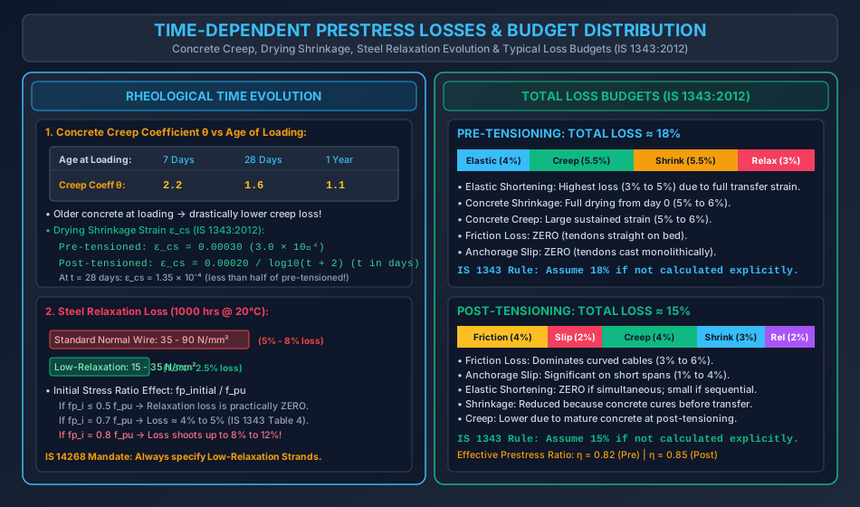
Per IS 1343:2012 / IS 456:2000 (Table 2), the creep coefficient depends on the age of concrete at the time of loading:
- At 7 days:
- At 28 days:
- At 1 year:
The loss of stress in the prestressing steel due to concrete creep is:
where is the sustained compressive stress in concrete at the c.g.s. under prestress plus permanent dead load.
3.2 Specific Creep Strain Method
In international practice (and older versions of IS 1343), creep is expressed in terms of specific creep (ultimate creep strain per unit sustained stress, typically ):
4. Loss Due to Drying Shrinkage of Concrete
Drying shrinkage is the decrease in concrete volume caused by moisture evaporation, occurring independently of external stress.
4.1 Shrinkage Strain Formulation (IS 1343:2012 Cl. 6.2.4)
The magnitude of shrinkage loss depends fundamentally on whether the structure is pre-tensioned or post-tensioned:
-
Pre-Tensioned Members: Because concrete is cast directly around tensioned steel on Day 0, the steel experiences the entire drying shrinkage strain from the initial setting of concrete through its design life:
-
Post-Tensioned Members: Post-tensioning tendons are stressed only after the concrete has hardened and cured (often at ). All shrinkage occurring prior to transfer does NOT cause loss of prestress! Only residual shrinkage taking place after transfer affects the tendon. Per IS 1343:2012:
where is the age of concrete at transfer in days.
- For transfer at :
(Crucial Finding: Post-tensioned members suffer less than half the shrinkage loss of pre-tensioned members).
5. Loss Due to Relaxation of Steel
Relaxation is the loss of tensile stress in high-strength steel held under constant strain over time (the metallurgical counterpart to concrete creep).
5.1 Factors Influencing Relaxation
- Initial Stress Level (): Below , relaxation is negligible. Above , relaxation increases exponentially with the initial stress ratio.
- Type of Steel: Low-relaxation (stabilized) strands manufactured under simultaneous heat treatment and high tension exhibit less than one-third the relaxation of standard cold-drawn wires.
- Temperature: Elevated temperatures dramatically accelerate relaxation.
5.2 Code Provisions (IS 1343:2012 Table 4)
For relaxation after 1000 hours at :
- Standard Normal Relaxation Steel: ( of initial stress).
- Low-Relaxation Strands (IS 14268): ( of initial stress).
6. Loss Due to Friction (Post-Tensioned Members Only)
In post-tensioned construction, friction between the tensioned tendon and the interior surface of the sheathing duct impedes the transmission of jacking force along the span.
6.1 Components of Friction
Friction arises from two distinct physical sources:
- Curvature Effect (Intentional Curvature): When a cable is deliberately profiled into a curve (e.g. parabolic trajectory to balance uniform gravity loads), the normal radial contact pressure between the curved tendon and duct generates frictional resistance: where is the coefficient of friction ( for steel tendon in metallic duct; in plastic HDPE duct), and is the cumulative angular change of the tendon profile in radians.
- Wobble / Wave Effect (Unintentional Misalignment): Even in nominally straight ducts, construction tolerances, formwork sagging, and concrete vibration cause unintentional localized deviations ("waves") in duct alignment: where is the wobble coefficient (friction per unit length, typically ), and is the distance from the jacking end in meters.
6.2 Governing Differential Formulation
Consider a differential segment of a curved tendon at distance from the jacking end, subtending an angle :
Integrating from the jack () to distance ():
When , the series expansion provides an accurate, widely used approximation:
6.3 Angular Change for Parabolic Tendons
For a parabolic tendon with central dip spanning length :
The slope at the end ():
- Angular change from end to midspan ():
- Total angular change from end to end ():
6.4 Jacking Methods: One-End vs Both-Ends Jacking
- Jacked from ONE End: The tendon force decays continuously across the entire span . The minimum prestressing force occurs at the far dead end ():
- Jacked from BOTH Ends Simultaneously: Tendon force is maximum () at both ends. The minimum force occurs symmetrically at the midspan (): Advantage: Jacking from both ends cuts the peak friction loss by more than , ensuring uniform compressive precompression across the girder.
7. Loss Due to Anchorage Slip (Post-Tensioned Members Only)
When the hydraulic tensioning jack releases the tendon, the conical wedges or split grips draw inward into the anchorage plate by a distance (wedge draw-in or slip) before biting tightly into the tendon steel.
7.1 Uniform Anchorage Slip Formulation
Let be the anchorage slip (typically to for wedge anchors; for threaded Macalloy bars):
- Average strain reduction across member length :
- Uniform loss of stress in the steel:
7.2 The Inverse Length Law
Because slip loss is inversely proportional to span length :
- For a short precast beam () with and :
- For a long bridge girder () with the same :
Rule of Thumb: In short post-tensioned members (), anchorage slip is the single most destructive loss mechanism. Threaded bar systems (Macalloy/Dywidag) must be used instead of wedge grips to eliminate slip.
8. Worked Numerical Examples with Complete Step-by-Step Verification
Problem 1: Pre-Tensioned Beam Comprehensive Loss Estimation
Statement:
A pre-tensioned concrete beam of cross-section spans . It is prestressed with high-tensile wires of total area located at an eccentricity below the centroidal axis. The initial stress in the wires immediately after transfer is . Concrete grade is M40 (), and steel modulus .
Given:
- Concrete shrinkage strain:
- Creep coefficient:
- Relaxation of steel: of initial stress
- Concrete density:
Calculate each individual loss of prestress, total loss in and percentage, and the final effective prestress force.
Solution:
Step 1: Section Properties & Initial Prestress Force:
- Cross-sectional area: .
- Moment of inertia:
- Initial prestress force:
- Self-weight per meter:
- Midspan bending moment due to self-weight:
Step 2: Concrete Stress at Steel Centroid ():
- Modular ratio:
- Stress components at steel level ( below centroid) at midspan:
- Net stress in concrete at level of steel:
Step 3: Loss Computations:
- Elastic Shortening Loss:
- Creep Loss:
- Drying Shrinkage Loss:
- Relaxation of Steel Loss:
Step 4: Total Loss & Effective Prestress:
- Total stress loss:
- Total percentage loss:
- Effective prestress remaining:
- Final effective prestress force:
Problem 2: Post-Tensioned Cable Friction & Anchorage Slip Verification
Statement:
A post-tensioned bridge girder of span is prestressed with a parabolic cable having an initial jacking force at the active jack. The tendon has a central dip of below the centroid at midspan, and aligns with the centroid at both ends.
Given:
- Friction coefficient:
- Wobble coefficient:
- Anchorage slip at jack:
- Steel modulus:
(a) If tensioned from ONE end only, calculate the prestress force at midspan and at the far dead end before anchorage slip.
(b) Compare the maximum friction loss if the cable is jacked from BOTH ends simultaneously.
(c) Determine the loss of prestress stress due to the anchorage slip over the span.
Solution:
Step 1: Tendon Geometry & Slope:
- Slope of parabolic profile at end ():
- Total angular change from end to end: .
Step 2: Case (a) - Jacking from ONE End Only (x = 0):
- At Midspan ():
- Angular change to midspan: .
- Total friction exponent:
- Prestress force at midspan:
- Friction loss at midspan:
- At Far Dead End ():
- Angular change across span: .
- Total friction exponent:
- Prestress force at far end:
- Friction loss at far end:
Step 3: Case (b) - Jacking from BOTH Ends Simultaneously:
- With jacks applied at both ends, the tendon force is symmetric.
- Maximum force exists at both ends ( and ).
- The minimum force occurs at midspan (), which is identical to .
- Comparison: Jacking from both ends reduces the maximum friction loss from () to (), saving over half of the friction loss across the critical central span.
Step 4: Case (c) - Anchorage Slip Loss:
- Slip over length :
Problem 3: Sequential vs Simultaneous Tensioning in Multi-Tendon Girders
Statement:
A post-tensioned bridge girder is prestressed with 4 identical cables, each stressed to an initial stress of . The cables are positioned symmetrically near the bottom of the section. The modular ratio is . Tensioning of any single cable induces an average compressive stress of in the concrete at the level of the cables.
(a) Determine the loss of prestress due to elastic shortening in each of the 4 cables when they are tensioned sequentially one by one in the order 1, 2, 3, 4.
(b) Calculate the average loss across all cables and compare with the theoretical formula.
(c) State the loss if all 4 cables are tensioned simultaneously.
Solution:
Step 1: Sequential Shortening Action:
- Total sustained concrete compressive stress when all 4 cables are stressed:
- Modular ratio: .
- Cable 1: Tensioned first. It undergoes shortening when Cable 2, Cable 3, and Cable 4 are subsequent tensioned (experiences 3 increments):
- Cable 2: Tensioned second. It undergoes shortening when Cable 3 and Cable 4 are tensioned (experiences 2 increments):
- Cable 3: Tensioned third. It undergoes shortening only when Cable 4 is tensioned (experiences 1 increment):
- Cable 4: Tensioned last. Because all other cables are already locked and no further tensioning occurs:
Step 2: Average Loss & Formula Verification:
- Average loss by direct summation:
- Theoretical formula check:
Step 3: Simultaneous Tensioning:
- If all 4 cables are pulled by 4 synchronized jacks at the same time:
9. Comparative Technical Summary: Loss Allocation
| Loss Mechanism | Pre-Tensioning System | Post-Tensioning System | Primary Design Variables |
|---|---|---|---|
| 1. Elastic Shortening | Significant () | Zero (simultaneous) or (sequential) | , concrete stress at c.g.s. |
| 2. Creep of Concrete | High () | Moderate () | Creep coefficient , sustained |
| 3. Shrinkage of Concrete | High () | Low () | Age at transfer , ambient humidity |
| 4. Relaxation of Steel | to of | to of | Steel grade (IS 14268 low relaxation), |
| 5. Friction | ZERO (straight cables) | Substantial () | Curvature , wobble , single vs double jacking |
| 6. Anchorage Slip | ZERO (monolithic bond) | High in short spans () | Wedge draw-in , span length |
| Total Typical Loss | (IS 1343 default) | (IS 1343 default) | Effective prestress ratio |
10. Construction Practices & Site Pitfalls
-
Ignoring Anchorage Slip in Short Spans (): Site Disaster: Using standard wedge grips with draw-in on short transfer girders (), causing over loss from slip alone and triggering premature flexural cracking. Remedy: Use threaded anchor bar systems (Macalloy/Dywidag) where draw-in slip is exactly zero, or shim the jacks to compensate for wedge seating.
-
Duct Damage & High Wobble Friction: Site Failure: Workers stepping on corrugated sheathing ducts during concrete placement, or tying ducts at excessive spacing (), leading to high duct wobble () and preventing full tendon elongation. Remedy: Support ducts on rigid reinforcement chairs spaced c/c; inspect ducts under low air pressure prior to concreting.
-
Wrong Tendon Tensioning Sequence: Pitfall: In a 4-cable post-tensioned beam, tensioning all lower cables first without considering intermediate eccentricities can induce excessive tensile stress and longitudinal cracking in the top flange at transfer. Remedy: Follow a staggered, symmetrical tensioning pattern (e.g. diagonal pairs or alternating top and bottom tendons).
11. Competitive Examination Traps & Problem-Solving Shortcuts
-
The Sequential Post-Tensioning Trap (GATE CE):
- A question asks: "A post-tensioned beam has 5 identical cables tensioned one by one. The ratio of average elastic shortening loss to the loss in a pre-tensioned beam with the same and is:"
- Formula: !
- Trap: Students instinctively answer (half), missing the discrete finite-tendon factor .
-
Simultaneous Tensioning Trap (ESE / SSC JE):
- Question asks: "In a post-tensioned member where all tendons are tensioned simultaneously, the loss of prestress due to elastic shortening of concrete is:"
- Answer: ZERO. The concrete shortens against the jack pressure before locking.
-
Pre-Tensioning Friction & Slip Trap (State AE / RRB JE):
- Question asks: "Calculate the loss due to friction and anchorage slip in a pre-tensioned railway sleeper."
- Answer: ZERO. Both friction and anchorage slip losses are physically impossible in pre-tensioning (wires are straight on long beds and cast monolithically in concrete).
-
Shrinkage Strain Value Trap:
- Pre-tensioned: (constant).
- Post-tensioned: (time-dependent).
12. Practice Problems & Examination Review Exercises
Level 1: Objective Conceptual (SSC JE / RRB JE)
-
Which of the following losses of prestress does NOT occur in a pre-tensioned concrete member?
- (A) Elastic shortening of concrete
- (B) Creep of concrete
- (C) Anchorage slip
- (D) Relaxation of steel
Answer: (C)
-
As per IS 1343:2012, if the age of concrete at transfer in a post-tensioned member is 28 days, the drying shrinkage strain is approximately:
- (A)
- (B)
- (C)
- (D)
Answer: (B)
-
For a parabolic tendon of span and central sag , the angular change between the two ends is:
- (A)
- (B)
- (C)
- (D)
Answer: (C)
Level 2: Multi-Concept Analytical (GATE CE)
- A post-tensioned beam of span is prestressed with 3 identical cables tensioned sequentially. The modular ratio is , and each cable induces stress in concrete at the c.g.s. The loss of prestress in the first cable tensioned is:
- (A)
- (B)
- (C)
- (D)
Solution: Cable 1 suffers loss due to the subsequent 2 cables (Cables 2 & 3).
. Correct choice is (B).
Level 3: Conventional Design Problem (UPSC ESE Mains)
- A post-tensioned prestressed concrete girder of I-section spans and carries an effective prestress force at midspan. The cable profile is parabolic with at midspan and concentric at the supports. (a) Calculate the initial jacking force required if the cable is jacked from both ends simultaneously (). (b) If an anchorage slip of occurs at both jacks upon release (), determine the loss of prestress stress due to slip and the length of the slip setback zone (). (c) Draw the variation of prestressing force along the span before and after anchorage slip.
13. Complete Topic Architecture & Upstream/Downstream Dependencies
                       REINFORCED & PRESTRESSED CONCRETE
                                     │
           ┌─────────────────────────┴─────────────────────────┐
           ▼                                                   ▼
Topic 10-01: Fundamentals & Systems                 Topic 10-02: Losses of Prestress
(Materials, Pre vs Post-tensioning,                 (Elastic, Creep, Shrinkage,
 Anchorages, Permissible Stresses)                  Relaxation, Friction, Slip)
                                                               │
           ┌───────────────────────────────────────────────────┼───────────────────────────────────┐
           ▼                                                   ▼                                   ▼
Topic 10-03: Analysis & Design of Beams             Effective Prestress Ratio           Topic 10-04: End Block Design
(Stress, Internal Couple, Load Balancing)           η = (1 - Loss Ratio)                (Bursting tension Fbst)
                                                    η ≈ 0.82 (Pre) | 0.85 (Post)
- Upstream Dependencies:
RCC-10-01: Materials properties (), pre-tensioning vs post-tensioning distinctions, and anchorage mechanisms.SOM-01-01&SOM-01-06: Elastic strain, Hooke's law, and time-dependent strain deformations.
- Downstream Dependencies:
RCC-10-03: Service flexural stress calculations require the exact effective prestress ratio .RCC-10-04: Anchorage bursting forces and transmission length are calculated using the transfer prestress force .
14. Verification & Standards References
- Bureau of Indian Standards:
- IS 1343: 2012 – Prestressed Concrete - Code of Practice (Second Revision) (Clauses 6.2.4, 6.2.5, 19.5, and Table 4).
- IS 456: 2000 (Reaffirmed 2021) – Plain and Reinforced Concrete - Code of Practice (Table 2 for Creep Coefficients).
- IS 14268: 2022 – Uncoated Stress Relieved Low Relaxation Seven-Ply Strand for Prestressed Concrete - Specification.
- Core Textbooks & Reference Manuals:
- Krishna Raju, N., Prestressed Concrete, 6th Edition, Tata McGraw-Hill Education (Chapter 4: Losses of Prestress).
- Lin, T.Y., and Burns, N.H., Design of Prestressed Concrete Structures, 3rd Edition, John Wiley & Sons.
- Pandit, G.S., and Gupta, S.P., Prestressed Concrete, CBS Publishers.