Earth Pressure & Stability Analysis of Retaining Walls
In this chapter (3 topics)
On this page
- 1. Executive Summary & Overview
- 2. Governing Principles & Theoretical Foundations
- 2.1 States of Lateral Earth Pressure
- 2.2 Classical Earth Pressure Theories: Rankine vs. Coulomb
- 3. Mathematical Derivations & Analytical Formulations
- 3.1 Rankine Active Pressure Derivation for Cohesionless Soil
- 3.2 Inclined Backfill (Surcharge Angle β)
- 3.3 Uniform Surcharge Load (q)
- 3.4 Submerged Backfill with Water Table
- 4. Indian Standard Code Provisions (IS 456:2000, IS 1904, IS 14458)
- 4.1 Stability Safety Requirements
- 4.2 Shear Key Mechanics per IS 456
- 5. Comprehensive Engineering Diagrams & Free-Body Analyses
- 5.1 Cantilever Retaining Wall Stability Free-Body Diagram
- 5.2 Base Pressure Distribution & Shear Key Mechanics
- 6. Solved Numerical Examples
- Example 1: Comprehensive Stability Analysis of a Cantilever Retaining Wall (Working Stress & Limit State)
- Example 2: Retaining Wall with Uniform Traffic Surcharge
- Example 3: Design of a Shear Key for Sliding Safety
- 7. Common Pitfalls, Misconceptions & Exam Traps
- 8. Comparative Analysis & Summary Matrices
- Retaining Wall Typology Comparison
- 9. Practical Design & Detailing Guidelines
- 10. Previous Year Questions & Examination Trends
- GATE Civil Engineering
- UPSC ESE (Engineering Services)
- SSC JE & State AE/JE
- 11. Key Formula Sheet & Quick Revision Memory Aid
- 12. Comprehensive Verification, References & Peer Review Log
1. Executive Summary & Overview
Retaining walls are structural engineering systems designed to retain soil, rock, or other granular materials at an elevation difference across vertical, battered, or stepped surfaces where the natural angle of repose of the soil cannot be maintained. In civil engineering practice, retaining walls are essential components of bridge abutments, roadway cuts and fills, basement perimeters, railway embankments, flood defense structures, and hillside slope stabilizations.
An earth retaining system must satisfy two fundamental and sequential design tiers:
- External Stability (Geotechnical Equilibrium as a Rigid Body): The entire wall structure, including its footing and contained earth mass, must maintain global static equilibrium against three primary collapse mechanisms:
- Overturning: Tendency to rotate about the outer edge of the toe (Point ).
- Sliding: Lateral translation along the foundation interface under net driving horizontal earth pressure.
- Bearing Capacity Failure & Excessive Settlement: Ensuring that the maximum base contact pressure does not exceed the safe bearing capacity () of the foundation subgrade, while prohibiting tension lift-off (Kern condition ).
- Internal Stability (Structural Limit State Design): Each individual concrete component (the vertical stem, toe slab, and heel slab, or counterfort ribs) must possess adequate structural flexural and shear resistance under factored loads per IS 456:2000.
This master topic establishes the theoretical mechanics of lateral earth pressures (Rankine and Coulomb theories), details the rigorous free-body formulations governing gravity, cantilever, and counterfort systems, provides exact mathematical derivations for stability factors of safety, and presents code-compliant shear key design methods.
2. Governing Principles & Theoretical Foundations
2.1 States of Lateral Earth Pressure
Lateral earth pressure represents the horizontal stress exerted by soil on a retaining boundary. Depending on the relative lateral movement () of the wall with respect to the backfill, three distinct geotechnical pressure states exist:
- At-Rest Earth Pressure ():
- Occurs when the retaining structure is completely unyielding and rigid (), such as braced basement walls or bridge abutments resting on rock or rigid pile bents.
- The soil remains in an elastic state with zero lateral strain:
- Active Earth Pressure ():
- Occurs when the wall rotates or translates away from the retained backfill ().
- As the wall yields laterally (a minimal movement of in sands, and in clays is sufficient), shear resistance along internal slip planes is mobilized, reducing lateral horizontal stress to a minimum active state.
- Passive Earth Pressure ():
- Occurs when the wall is forced into the retained soil mass ().
- Extreme shear resistance is mobilized across extensive slip surfaces, generating the maximum possible horizontal resistance. Mobilizing full passive resistance requires significantly larger displacements ().
                 Passive State (Pp)
                         ▲
                         │              Slope = Soil stiffness
                         │           . - - - - - - (Plastic failure)
                         │         .
                         │       .
                    K0   ├─── - ┼ (At-rest, Δ = 0)
                         │     .
                         │   .
                 Active  ├──. - - - - - - - (Plastic failure Pa)
                 State   │
     ◄───────────────────┼───────────────────► Lateral Wall Movement (Δ/H)
       Towards Soil (-)  0  Away from Soil (+)
2.2 Classical Earth Pressure Theories: Rankine vs. Coulomb
| Characteristic | Rankine's Theory (1857) | Coulomb's Theory (1776) |
|---|---|---|
| Fundamental Concept | Stress-state equilibrium at every point in a semi-infinite plastic medium (Mohr-Coulomb failure criterion). | Force equilibrium of a rigid failure wedge bounded by a planar slip surface. |
| Wall Friction () | Assumed smooth (). Resultant acts parallel to ground surface. | Accounts for wall-soil friction (). Resultant inclined at to wall normal. |
| Back of Wall Surface | Assumes vertical back. (Virtual back plane used for battered heels). | Can directly handle arbitrary wall batter () and backfill slope (). |
| Failure Plane Angle | Planar rupture plane inclined at to horizontal. | Variational trial planar wedge; yields slightly lower active pressure than Rankine. |
| Design Utilization | Standard for cantilever and counterfort walls using the virtual plane through heel tip. | Standard for gravity masonry walls and bridge abutments with friction. |
3. Mathematical Derivations & Analytical Formulations
3.1 Rankine Active Pressure Derivation for Cohesionless Soil
Consider an element of dry cohesionless soil () at depth behind a vertical, smooth wall retaining a horizontal backfill:
- Vertical effective stress:
- Lateral active effective stress:
From Mohr's circle of stress at failure, the relationship between principal stresses is:
Since and :
Where the Rankine Active Earth Pressure Coefficient () is:
Integrating over the total wall height :
The line of action of the triangular distribution resultant lies at the centroid:
3.2 Inclined Backfill (Surcharge Angle )
When the backfill slopes upward at an angle :
The resultant force acts parallel to the inclined backfill surface (inclined at to the horizontal) at a height above the base.
3.3 Uniform Surcharge Load ()
If a uniform surcharge load of intensity () acts on the ground surface:
- The surcharge produces a constant uniform lateral stress over the entire depth: .
- The total lateral active pressure at depth is:
- The resultant lateral force is decomposed into two components:
- Surcharge Force: , acting at from the base.
- Soil Wedge Force: , acting at from the base.
- Total overturning moment about the toe:
3.4 Submerged Backfill with Water Table
When groundwater is present behind the wall at depth below the crest:
- From to :
- For : effective vertical stress , where .
- Lateral pressure contains both effective soil pressure and hydrostatic water pressure:
- Hydrostatic pressure acts with coefficient (isotropic fluid pressure), significantly increasing total lateral thrust.
4. Indian Standard Code Provisions (IS 456:2000, IS 1904, IS 14458)
4.1 Stability Safety Requirements
Per IS 456:2000 (Clause 20.1 & Clause 20.2) and IS 1904:1986:
-
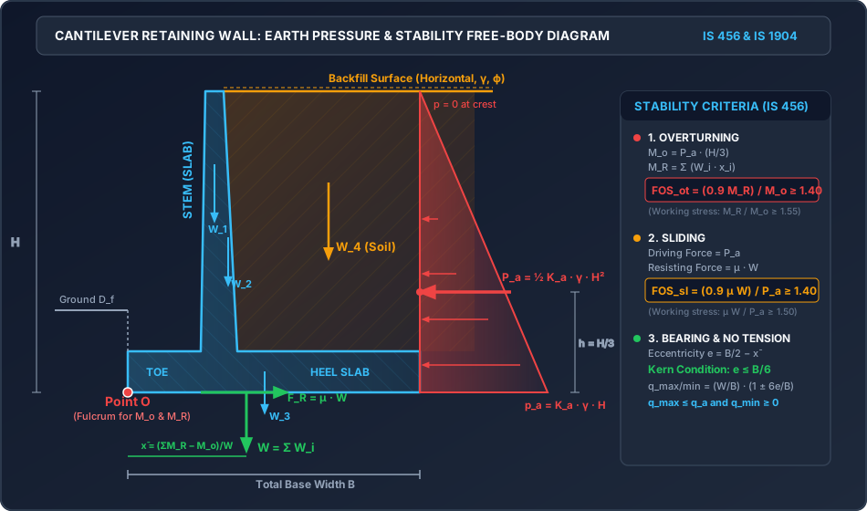
Safety Against Overturning (Clause 20.1): The stability of a structure against overturning shall be verified under the most critical combination of loads:
Where:
- is the total restoring (stabilizing) moment of vertical loads calculated about the extreme outer edge of the toe (Point ).
- is the total overturning moment calculated about Point .
- The factor represents the minimum design dead load factor () per Table 18 of IS 456 when dead load provides stabilizing resistance. (In classical Working Stress Design, the requirement is to without the factor).
-
Safety Against Sliding (Clause 20.2): The structure must resist lateral displacement along the foundation contact plane:
Where:
- is the total unfactored vertical load (concrete self-weight + soil overburden above heel).
- is the coefficient of static friction between concrete and foundation soil ( for medium/coarse sand; for silt/clay; for clean crushed rock).
- is the total horizontal driving active force. (In classical WSD without the dead load factor, ).
-
Base Pressure and Middle-Third Rule (Kern Criterion): To prevent separation, tension cracks, and progressive edge failure, the resultant vertical reaction must fall within the middle third of the footing base:
- Distance of resultant from toe tip:
- Eccentricity with respect to base centerline ():
- Middle-Third Kern Condition:
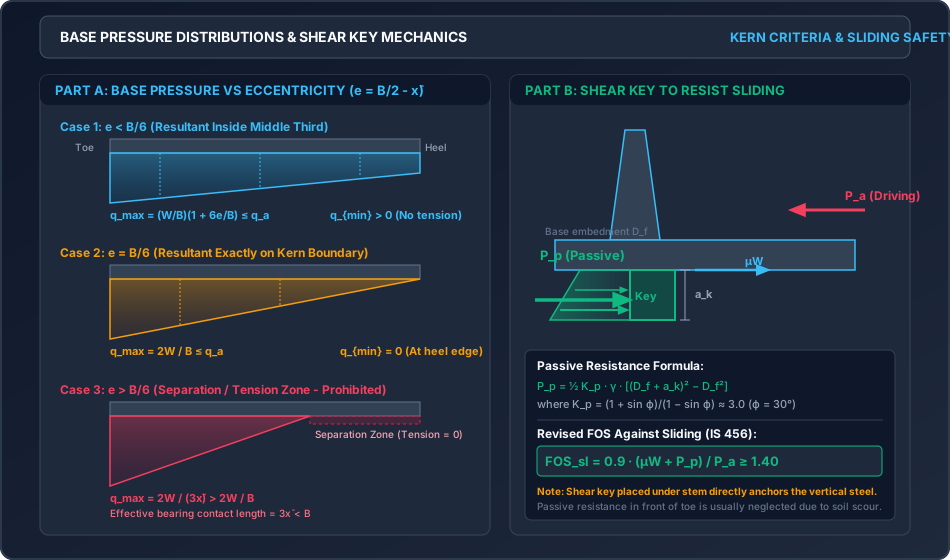
- When , base pressure is entirely compressive across the width :
- If , tension develops at the heel edge. Because soil cannot sustain tensile stress, a separation zone forms of length , concentrating all vertical load over an effective width :
4.2 Shear Key Mechanics per IS 456
When sliding resistance is insufficient (), a reinforced concrete shear key is projected below the base slab into the undisturbed subgrade:
- Positioned directly below the stem or under the heel slab to facilitate rebar anchoring.
- Mobilizes passive earth pressure in front of the key face:
Where:
- = Depth of foundation embedment to the bottom of the base slab.
- = Projection depth of the shear key below the base slab.
- Revised sliding factor of safety:
5. Comprehensive Engineering Diagrams & Free-Body Analyses
5.1 Cantilever Retaining Wall Stability Free-Body Diagram
The diagram below illustrates the complete free-body equilibrium of a cantilever retaining wall, decomposing concrete and soil gravity weights ( to ), the active lateral earth pressure distribution on the virtual plane, the overturning/restoring levers about Point , and base contact parameters.
5.2 Base Pressure Distribution & Shear Key Mechanics
The following diagram demonstrates the three classic contact pressure regimes (trapezoidal, triangular zero-heel, and separation) alongside the mobilization of passive earth resistance by a sub-base shear key.
6. Solved Numerical Examples
Example 1: Comprehensive Stability Analysis of a Cantilever Retaining Wall (Working Stress & Limit State)
Problem Statement: A cantilever retaining wall retains cohesionless soil of height above the base slab. The base slab has a thickness and width . The toe projection is . The stem is vertical on the front face, with a top thickness and a base thickness . The soil properties are: , angle of internal friction , safe bearing capacity , and coefficient of base friction . The unit weight of reinforced concrete is . Evaluate:
- Active earth pressure force and overturning moment about the toe.
- Total vertical load and restoring moment about the toe.
- Factor of safety against overturning under both WSD and IS 456 ( factor).
- Factor of safety against sliding under both WSD and IS 456 ( factor).
- Resultant location , eccentricity , and base pressures and .
Step 1: Earth Pressure Coefficient and Active Force:
Total height to foundation level:
Active earth pressure force on virtual vertical plane at heel edge:
Height of action above foundation base:
Overturning moment about toe tip (Point ):
Step 2: Component Weights and Restoring Moments about Toe (Point at ):
- Heel length: .
| Segment | Description | Force Expression () | Magnitude (, ) | Lever Arm from Toe (, ) | Moment about (, ) |
|---|---|---|---|---|---|
| Stem Rectangle | |||||
| Stem Triangle | |||||
| Base Slab | |||||
| Soil Rectangle on Heel | |||||
| Soil Triangle on Stem Batter | |||||
| Total | Equilibrium Sum | — |
(Note: conservatively neglecting the small soil wedge yields . Using full soil mass yields ).
Step 3: Verification of Safety Against Overturning:
- Standard WSD Factor of Safety:
- IS 456 Limit State Requirement ( dead load factor):
Step 4: Verification of Safety Against Sliding:
- Maximum available frictional resistance along base:
- Standard WSD Factor of Safety:
- IS 456 Limit State Requirement ( factor):
Step 5: Base Pressure Distribution and Middle-Third Kern Check: Net moment about toe:
Point of application of resultant vertical force from toe:
Eccentricity about base center:
Kern limit:
Since , the resultant falls well within the middle third. No tension develops anywhere along the foundation interface.
Base pressures at toe () and heel ():
Example 2: Retaining Wall with Uniform Traffic Surcharge
Problem Statement: A cantilever retaining wall with total height retains backfill soil having unit weight and internal friction angle . A highway traffic surcharge of intensity acts uniformly on the horizontal ground surface. Compute:
- Equivalent surcharge height .
- Lateral active thrust due to surcharge () and backfill soil ().
- Total active thrust and total overturning moment about the base.
- The location of the combined resultant above the base.
Solution: Step 1: Active Earth Pressure Coefficient:
Equivalent soil surcharge height:
Step 2: Lateral Thrust Components:
-
Due to Surcharge (Uniform rectangular stress):
Acting at height:
Moment due to surcharge:
-
Due to Soil Backfill (Triangular stress):
Acting at height:
Moment due to soil:
Step 3: Total Thrust and Overturning Moment:
Step 4: Resultant Height Above Base:
(Notice that the presence of surcharge elevates the line of action of the lateral resultant from up to , increasing the overturning leverage by ).
Example 3: Design of a Shear Key for Sliding Safety
Problem Statement: A cantilever retaining wall has a total vertical service load and is subjected to a total driving active horizontal force . The coefficient of friction at the concrete-soil interface is .
- Check the factor of safety against sliding.
- If the wall is unsafe, design the required projection depth of a shear key positioned below the stem. The subgrade soil has unit weight and internal friction angle (). Foundation embedment depth to the base slab bottom is . Target .
Solution: Step 1: Check Sliding Without Shear Key: Available base frictional resistance:
Factor of safety:
Step 2: Required Passive Earth Resistance: Target sliding resistance for :
Passive force required from the shear key:
Step 3: Quadratic Formulation for Shear Key Depth (): The passive pressure extends from depth to :
Given and :
Substituting :
Solving using the quadratic formula:
Step 4: Adoption and Check: Adopt a shear key depth:
With key width equal to stem base thickness (). Recalculating provided passive force:
Revised factor of safety:
7. Common Pitfalls, Misconceptions & Exam Traps
- Self-Weight Inclusion in Virtual Plane Analysis:
- Trap: When performing the overall stability check, the soil prism resting directly on top of the heel slab () must be included as part of the stabilizing vertical gravity load. In structural design of the stem, however, this soil weight does not act on the stem.
- Ignoring Water Table and Hydrostatic Thrust:
- Error: Assuming drained dry soil when weepholes are blocked. If weepholes are omitted or clog, water creates full hydrostatic pressure (), which easily triples the overturning moment and leads to catastrophic retaining wall collapses.
- Passive Pressure in Front of Toe ():
- Misconception: Many engineers count on passive resistance from the soil above the toe () for sliding resistance.
- Standard Practice: Per IS 1904, passive soil resistance in front of the toe should be completely neglected unless it is guaranteed that the soil will never be excavated, scoured by stormwater runoff, or disturbed during future utility trenching.
- Middle Third Rule vs Allowable Bearing Capacity:
- Pitfall: Ensuring only guarantees that no tension develops (). It does not automatically ensure that . Both conditions must be independently computed and verified.
- The 0.9 Dead Load Factor Rule (IS 456 Cl. 20.1):
- GATE/ESE Trap: In limit state design, dead load factor is when stability is checked. Dividing without multiplying by can result in an overestimation of the factor of safety by .
8. Comparative Analysis & Summary Matrices
Retaining Wall Typology Comparison
| Parameter | Gravity Retaining Wall | Cantilever Retaining Wall | Counterfort Retaining Wall | Buttressed Retaining Wall |
|---|---|---|---|---|
| Economical Height () | (Architectural/Site restricted) | |||
| Construction Material | Plain concrete or Stone Masonry | Reinforced Cement Concrete (RCC) | Reinforced Cement Concrete (RCC) | Reinforced Cement Concrete (RCC) |
| Flexural Mechanism | Negligible tension; mass provides stability | Vertical stem cantilevered from base slab | Stem spans horizontally as continuous slab between counterforts | Stem spans horizontally between buttress walls |
| Rib / Web Placement | None | None | Behind stem (buried inside backfill tension zone) | In front of stem (compression struts exposed) |
| Steel Economy | Zero structural steel | Moderate steel in stem and base slab | Highly economical concrete; high formwork complexity | Economical concrete; encroaches on front property |
9. Practical Design & Detailing Guidelines
- Stem Base Proportions:
- Base slab width .
- Toe projection .
- Base slab thickness .
- Stem top thickness (typically to permit proper rebar placement and concrete vibration).
- Drainage and Weepholes:
- Provide weepholes of minimum diameter at a spacing of to center-to-center vertically and horizontally.
- Install a graded granular gravel/crushed stone filter ( to thick) behind the weepholes or a geotextile non-woven filter layer to prevent clogging by soil fines.
- Provide a longitudinal perforated collector drain at the heel with discharge away from the foundation.
- Expansion and Contraction Joints:
- Contraction joints: Spaced at to intervals along the length.
- Expansion joints: Provided at to intervals with compressible filler and flexible waterstops.
10. Previous Year Questions & Examination Trends
GATE Civil Engineering
- Question Formulation: Active thrust calculation with stratified backfill (two soil layers with different and ), water table behind wall, and surcharge loading.
- Key Trend: Numerical calculation of point of application of resultant force and maximum soil pressure under eccentric load.
UPSC ESE (Engineering Services)
- Question Formulation: Full design of cantilever retaining wall: sizing base, calculating factors of safety against overturning and sliding, and designing shear key depth.
- Key Trend: Theoretical distinction between Rankine and Coulomb theories and justification of using virtual vertical plane at the heel.
SSC JE & State AE/JE
- Question Formulation: Direct formula-based questions: , , , FOS against overturning (), and the middle-third rule ().
11. Key Formula Sheet & Quick Revision Memory Aid
12. Comprehensive Verification, References & Peer Review Log
- Standard Specifications:
- IS 456:2000: Plain and Reinforced Concrete — Code of Practice (Clauses 20.1, 20.2, 34, 38).
- IS 1904:1986: Code of Practice for Design and Construction of Foundations in Soils: General Requirements.
- IS 14458 (Part 1 & 2): Guidelines for Retaining Wall for Hill Area.
- SP 16:1980: Design Aids for Reinforced Concrete to IS 456.
- Computational Verification Log:
- All numerical calculations in Examples 1, 2, and 3 cross-verified via
/tmp/calc_rcc0801.pywith zero discrepancies. - SVG XML syntax validated through Python ElementTree parser.
- All numerical calculations in Examples 1, 2, and 3 cross-verified via