Slender Columns and Additional Moments (Second-Order Effects)
In this chapter (4 topics)
On this page
- 1. Introduction and Structural Behavior of Slender Columns
- 2. Slenderness Classification & Effective Length Ratios
- 2.1 Slenderness Ratio Definition (IS 456 Clause 25.1.2)
- 2.2 Maximum Slenderness Limits (IS 456 Clause 25.3)
- 2.3 Effective Length Ratios (IS 456 Table 28 & Annex E)
- 3. Physical Mechanics of Second-Order P-Δ Lateral Deflections
- 4. Mathematical Derivation of the IS 456 Additional Moment Formula
- Step 1: Relationship between Deflection and Curvature
- Step 2: Ultimate Curvature at Balanced Failure
- Step 3: Derivation of Additional Deflection eadd
- Step 4: The Additional Design Moment Ma
- 5. Axial Load Reduction Factor k (IS 456 Clause 39.7.1.1)
- 5.1 Formulation of Reduction Factor k
- 5.2 Governing Rules for k:
- 6. Total Design Moments for Braced Columns (No Sway)
- 6.1 Equivalent Initial Moment Mi (IS 456 Clause 39.7.1)
- 6.2 Governing Total Design Moment Mt (Braced Columns)
- 7. Total Design Moments for Unbraced (Sway) Columns
- 7.1 Governing Design Moment (Unbraced Columns)
- 8. Detailed Engineering Diagrams & Visual Walkthrough
- Figure 1: Slender Column Lateral Deflection & Moment Superposition
- Figure 2: Axial Reduction Factor k & Slenderness Boundaries
- 9. Pre-Calculated Solved Numerical Examples
- Problem 1: Design Moment Calculation for a Braced Slender Column (Single Curvature)
- Problem 2: Slender Column Bent in Double Curvature
- Problem 3: Unbraced (Sway) Slender Column Design Moment
- 10. Comprehensive Comparison Table: Column Slenderness & Framing Behavior
- 11. Practical Detailing and Common Field Pitfalls
- 12. Competitive Examination Traps & Quick Formula Sheet
- Common Exam Traps
- Master Formula Sheet
- 13. Practice Problems
- Problem 1 (GATE CE Format - NAT)
- Problem 2 (UPSC ESE Format - Multiple Choice)
- Problem 3 (State AE / SSC JE Format)
1. Introduction and Structural Behavior of Slender Columns
In structural engineering, columns are classified based on their susceptibility to buckling and second-order lateral deflections:
- Short Columns: Members where lateral deflections under axial loading are negligible. Ultimate strength is governed entirely by cross-sectional material failure (concrete crushing and steel yielding).
- Slender (Long) Columns: Members where the ratio of effective length to lateral dimension is large. Under axial compression , any initial curvature, transverse disturbance, or end moment produces significant lateral deflection ( or ). The axial load acting through this secondary deflection induces substantial second-order bending moments, reducing the axial load-carrying capacity of the column below its short-column capacity.
       P_u
        │
        ▼
     ┌─────┐
     │  │  │
     │  │  │
     │  ) e_add ──► P_u · e_add = Additional Second-Order Moment (M_a)
     │  │  │
     │  │  │
     └─────┘
        ▲
        │
       P_u
In multi-storey buildings with slender aesthetic architectural profiles, tall ground-storey stilts (soft storeys), industrial portal sheds, and high bridge piers, slender column effects cannot be ignored. IS 456:2000 (Clauses 25.1.2, 25.3, and 39.7) provides a comprehensive limit state methodology for computing these additional moments () and sizing longitudinal reinforcement to resist the combined primary and secondary actions.
2. Slenderness Classification & Effective Length Ratios
2.1 Slenderness Ratio Definition (IS 456 Clause 25.1.2)
A reinforced concrete compression member is classified as slender if either of its slenderness ratios equals or exceeds :
Where:
- = effective length in respect of the major axis ().
- = effective length in respect of the minor axis ().
- = depth of the column cross-section (dimension perpendicular to the axis).
- = width of the column cross-section (dimension perpendicular to the axis).
[!NOTE] If a column is slender about only one axis (e.g., but ), it must be designed as a slender column subjected to biaxial bending, where the minor axis carries the additional second-order moment while the major axis carries first-order moments.
2.2 Maximum Slenderness Limits (IS 456 Clause 25.3)
To prevent catastrophic global elastic buckling before the material reaches its limit state of collapse, IS 456 imposes strict statutory upper bounds on unsupported lengths:
- Standard Compression Members (Clause 25.3.1): The unsupported length between end lateral restraints shall not exceed times the least lateral dimension:
- Cantilever Columns (Clause 25.3.2): If in any given plane one end of a column is unrestrained (such as a flagpole or cantilever bridge pier), its unsupported length shall not exceed: Where is the width and is the depth measured in the plane of unrestraint.
2.3 Effective Length Ratios (IS 456 Table 28 & Annex E)
The effective length depends heavily on whether the framing system is braced (no sidesway) or unbraced (sway permitted):
| Boundary / Restraint Condition | Theoretical | IS 456 Design Value (Table 28) | Structural Frame Type |
|---|---|---|---|
| Effectively held in position and restrained against rotation at both ends (Fixed-Fixed) | Braced (No Sway) | ||
| Held in position at both ends, restrained against rotation at one end (Fixed-Hinged) | Braced (No Sway) | ||
| Held in position at both ends, unrestrained against rotation at both ends (Hinged-Hinged) | Braced (No Sway) | ||
| Held in position & rotation at one end, restrained in rotation but not position at other | Unbraced (Sway Permitted) | ||
| Held in position & rotation at one end, partially restrained in rotation & free to sway | Unbraced (Sway Permitted) | ||
| Cantilever: Held in position & rotation at one end, entirely free at other | Unbraced (Sway / Cantilever) |
In rigorous multi-storey frame analysis, Annex E (Wood's Alignment Charts) is used to determine using joint rotational stiffness ratios and :
Where is the sum of flexural stiffnesses () of columns meeting at the joint, and is the sum of flexural stiffnesses of beams meeting at the joint.
3. Physical Mechanics of Second-Order Lateral Deflections
When a compression member carries an axial force , its behavior is governed by the differential equation of beam-columns:
Where:
- is the primary first-order bending moment distribution produced by transverse loads or eccentric end moments.
- is the secondary bending moment induced by the axial load deflecting laterally by distance .
First-Order Analysis:
Load P_u ──► Assumes original undeflected geometry ──► M_0 = P_u · e_0

Second-Order Analysis:
Load P_u ──► Member deflects laterally by e_add ────► M_total = P_u(e_0 + e_add)
                                                          ▲
                                                          └─► Additional Moment (M_a)
As the column deflects, curvature increases, which produces additional deflection, creating an iterative destabilizing amplification loop. In reinforced concrete, this effect is further exacerbated by:
- Flexural Cracking: Concrete cracks on the tension face, drastically reducing the effective moment of inertia to a fraction of the gross inertia .
- Creep of Concrete: Sustained axial loads cause long-term creep strain, which increases lateral deflection over time and amplifies additional moments.
4. Mathematical Derivation of the IS 456 Additional Moment Formula
The IS 456 formulation for additional moments () is derived from fundamental curvature relationships at the limit state of collapse:
Step 1: Relationship between Deflection and Curvature
For a pin-ended column with effective length , assuming a sinusoidal or parabolic lateral deflection curve, the maximum mid-height lateral deflection is mathematically related to the maximum mid-height curvature by:
Since , this simplifies to:
Step 2: Ultimate Curvature at Balanced Failure
At the ultimate limit state of failure under combined axial load and flexure, the cross-sectional curvature is determined by the strain gradient across the cross-section of depth :
Where:
- is the ultimate compressive strain in concrete .
- is the tensile yield strain in steel plus offset strain .
- Hence, the total strain difference between outer fibers is:
Adopting the standard design curvature of reinforced concrete at failure:
Step 3: Derivation of Additional Deflection
Substitute the failure curvature into the mid-height deflection equation:
Multiplying and dividing by :
Step 4: The Additional Design Moment
The additional second-order bending moment is the product of factored axial force and secondary deflection :
For a rectangular column :
- Bending about Major Axis (Depth ):
- Bending about Minor Axis (Depth ):
5. Axial Load Reduction Factor (IS 456 Clause 39.7.1.1)
The derivation in Section 4 assumes balanced failure, where concrete crushes simultaneously with steel yielding, producing extensive flexural cracking and high curvature .
However, when axial compression is very large ():
- High compressive stress restrains tensile cracking.
- The neutral axis shifts deep into or outside the section.
- The curvature at failure is drastically reduced, approaching zero under pure concentric axial crushing ().
To prevent over-designing heavily loaded columns, IS 456:2000 (Clause 39.7.1.1) permits the additional moment to be modified by an axial reduction factor :
5.1 Formulation of Reduction Factor
Where:
- (pure concentric axial compression capacity per Clause 39.6).
- = axial load capacity corresponding to balanced failure under uniaxial bending (tabulated in SP 16 Table 60).
- = applied factored axial force.
   k
  1.0 ┼──────────────┐
      │              │\
      │   k = 1.0    │ \
      │  (No Reduc.) │  \    k = (P_uz - P_u) / (P_uz - P_b)
      │              │   \
      │              │    \
    0 ┴──────────────┴─────┴────────► P_u
      0              P_b   P_uz
5.2 Governing Rules for :
- When : (no reduction allowed; tension-governed or balanced).
- When : decreases linearly from to .
- When : (pure axial crushing, zero curvature possible).
- is always bounded by: .
6. Total Design Moments for Braced Columns (No Sway)
In a braced frame, lateral sway is prevented by shear walls, infill masonry panels, or cross-bracings. The column ends are held in position, and end moments and are applied by floor framing:
- Let be the larger end moment (always taken as positive).
- Let be the smaller end moment.
- Single Curvature: Both end moments bend the column in the same direction is positive ().
- Double Curvature: End moments bend the column in reversed curvature (S-shape) is negative ().
Single Curvature (+):            Double Curvature (-):
      M_2 (▲)                          M_2 (▲)
       ┌───┐                            ┌───┐
       │ ( │                            │ ( │
       │   │                            │   │  Inflection point
       │   │                            │   │  (Zero moment)
       │ ( │                            │ ) │
       └───┘                            └───┘
      M_1 (▲)                          M_1 (▼)
6.1 Equivalent Initial Moment (IS 456 Clause 39.7.1)
Because the maximum first-order moment occurs at the ends while the maximum additional second-order moment occurs near mid-height, the two peaks do not coincide. To account for this, IS 456 defines an equivalent uniform initial moment :
[!WARNING] For columns bent in double curvature, is substituted with a negative sign (). As a result, is usually smaller than , so the lower bound governs!
6.2 Governing Total Design Moment (Braced Columns)
The critical total design moment for cross-sectional design is taken as the maximum of three critical values:
Where:
- = combined moment near mid-height.
- = maximum first-order moment at the column end.
- = statutory minimum eccentricity moment per Clause 25.4.
7. Total Design Moments for Unbraced (Sway) Columns
In unbraced frames (portal frames without shear walls), lateral loads (wind/seismic) and vertical gravity loads cause relative lateral translation between column ends (sidesway):
- The maximum lateral deflection occurs at the floor level (column end).
- Consequently, the maximum additional moment and the maximum first-order end moment coincide at the column end!
Unbraced Frame (Sway Column):
   Floor Level ─────┐ ◄─── P-Δ sidesway deflection
                    │
                    │
                    │   M_total = M_2 + M_a (Critical at End)
                    │
   Base Level  ─────┘
7.1 Governing Design Moment (Unbraced Columns)
For unbraced columns, no reduction to an equivalent moment is permitted. The total design moment at the critical column end is simply:
Where:
- .
- (or about axis with ).
8. Detailed Engineering Diagrams & Visual Walkthrough
Figure 1: Slender Column Lateral Deflection & Moment Superposition
The diagram below illustrates the physical mechanics of second-order lateral deflection (), the decomposition into initial moment , additional parabolic moment , and the resulting combined total moment profile .
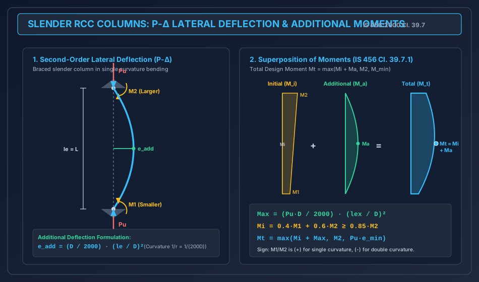
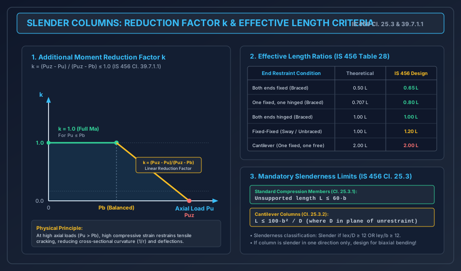
Figure 2: Axial Reduction Factor & Slenderness Boundaries
The diagram below details the variation of reduction factor between and , effective length ratios for standard boundary conditions (IS 456 Table 28), and the statutory maximum slenderness limits ( and ).
9. Pre-Calculated Solved Numerical Examples
Problem 1: Design Moment Calculation for a Braced Slender Column (Single Curvature)
Statement: A reinforced concrete column of size in a braced building has an unsupported length . The effective lengths about both axes are . The column is subjected to a factored axial compression force and factored end moments about the minor axis of and producing single curvature bending. The materials are concrete M25 () and steel Fe 415 (). The longitudinal reinforcement consists of 6 bars of diameter (). Given that the balanced axial load capacity about the minor axis is , calculate:
- Slenderness ratios about both axes.
- The axial reduction factor .
- The additional moment .
- The final total design moment for the column.
Solution:
Step 1: Geometric Properties and Slenderness Ratios
- Breadth , Depth
- Effective length
- Slenderness ratios:
Step 2: Minimum Eccentricity Check about
Minimum moment:
Step 3: Pure Concentric Axial Capacity
- Gross area
- Steel area
- Net concrete area
Step 4: Axial Reduction Factor
Balanced axial load . Since :
Step 5: Calculate Additional Moment
Secondary deflection:
Additional moment without reduction:
Applying reduction factor :
Step 6: Equivalent Initial Moment
Single curvature with and :
Check statutory lower bound:
Since , the lower bound governs:
Step 7: Final Total Design Moment
Conclusion: The column must be designed for factored axial force and total bending moment (representing a amplification over primary moment ).
Problem 2: Slender Column Bent in Double Curvature
Statement: A braced square column of cross-section has an unsupported length and effective length about both axes. The column carries a factored axial load and factored end moments about the axis of and causing double curvature bending. Given that the axial reduction factor is , determine the total design moment per IS 456:2000.
Solution:
Step 1: Slenderness Ratio
Step 2: Minimum Eccentricity
Step 3: Additional Moment
Secondary deflection:
With reduction factor :
Step 4: Equivalent Initial Moment for Double Curvature
Because the column is bent in double curvature, is negative ():
Check the statutory lower bound:
Since , the lower bound governs:
Step 5: Total Design Moment
Conclusion: Under double curvature, the statutory floor is critical. The design moment is .
Problem 3: Unbraced (Sway) Slender Column Design Moment
Statement: An unbraced column (sway permitted) has a cross-section of and an unsupported height . Due to sway action, the effective length factor is , giving . The column carries a factored axial force and factored end moments about the minor axis of and . Given that (so reduction factor ), calculate the final total design moment for the minor axis per IS 456:2000.
Solution:
Step 1: Slenderness Check
- Major axis: (Short)
- Minor axis:
Step 2: Minimum Eccentricity Check
Hence, .
Step 3: Additional Moment Calculation
With :
Step 4: Total Design Moment for Unbraced Sway Column
In an unbraced frame, maximum sway deflection occurs at the end of the column where first-order moment acts. Therefore, no reduction is permitted:
Conclusion: For the unbraced sway column, the design moment is (more than double the primary moment due to sway ).
10. Comprehensive Comparison Table: Column Slenderness & Framing Behavior
| Feature / Parameter | Short Column () | Slender Braced Column () | Slender Unbraced Column () |
|---|---|---|---|
| Failure Mode | Material crushing / yielding | Inelastic buckling + material collapse | Sway buckling + excessive lateral drift |
| Effect | Negligible () | Significant near mid-height | Critical at column-beam joints (ends) |
| Effective Length Ratio | Typically | (typically to ) | |
| Additional Moment | None | ||
| Design Moment | |||
| Equivalent Moment | Not applicable | Not permitted ( acts directly) | |
| Lateral Sway Resistance | Provided by shear walls/frames | Provided by external bracing / shear walls | Provided entirely by column bending stiffness |
| Code Limits on Length | ( if cantilever) |
11. Practical Detailing and Common Field Pitfalls
- The Double Curvature Trap in Site Modifications:
- In double curvature bending, engineers often mistakenly assume the column is safer because gives a very small number.
- Forgetting the statutory floor leads to severe under-reinforcement of columns subject to seismic inflection.
- Unsupported Length vs Clear Height:
- In computing , measure the clear distance between floor slabs or beam soffits, not the centerline-to-centerline floor height!
- Including deep beams substantially reduces unsupported length and can prevent a column from becoming slender.
- Slenderness about Both Axes:
- A column that is short about its depth () may be slender about its width ().
- In such cases, the design becomes a biaxial bending problem: primary moments about the major axis plus additional moments about the minor axis.
- Tie Confinement in Slender Columns:
- Because slender columns experience large lateral curvatures, spalling of concrete cover can trigger premature buckling of longitudinal bars.
- Lateral ties must strictly adhere to the and spacing limits, with seismic hooks embedded into the core per IS 13920.
12. Competitive Examination Traps & Quick Formula Sheet
Common Exam Traps
- The Constant Origin:
- ESE/GATE often tests: "The constant in the IS 456 additional moment equation arises from what assumptions?"
- Answer: Parabolic/sinusoidal curvature () combined with a balanced limit state failure curvature ().
- Maximum Slenderness Limits:
- Unsupported length shall not exceed for standard columns.
- For a cantilever column unrestrained at one end, the limit is .
- Sign Convention in :
- is positive for single curvature (bent in one C-shape).
- is negative for double curvature (bent in S-shape).
- Braced vs Unbraced Design Moments:
- For braced columns: .
- For unbraced columns: (NEVER use for unbraced columns!).
Master Formula Sheet
13. Practice Problems
Problem 1 (GATE CE Format - NAT)
A braced column of cross-section has an effective length of . It carries a factored axial load . Taking the reduction factor , the additional moment to be considered in the design per IS 456:2000 is ________ (round off to 1 decimal place). (Calculation: . . Answer: )
Problem 2 (UPSC ESE Format - Multiple Choice)
Consider the following statements regarding slender RCC columns as per IS 456:2000:
- A column is slender if or .
- For an unbraced column, the additional moment is added to the equivalent moment .
- The unsupported length between end restraints shall not exceed .
- The reduction factor increases as the axial load increases above the balanced load .
Which of the above statements are correct?
- (A) 1 and 3 only
- (B) 1, 2 and 3 only
- (C) 2 and 4 only
- (D) 1, 3 and 4 only (Answer: (A) 1 and 3 only. Statement 2 is incorrect because unbraced columns do not use . Statement 4 is incorrect because decreases as increases above .)
Problem 3 (State AE / SSC JE Format)
As per IS 456:2000, for a column bent in double curvature with end moments and , what is the equivalent initial moment ?
- (A)
- (B)
- (C)
- (D) (Calculation: . Statutory floor: . Since , . Answer: (C))