RCC-08-02 Chapter 08 · Design of Retaining Walls

Design of Cantilever Retaining Walls (Stem, Heel & Toe Slab Proportioning)

1. Executive Summary & Overview

The cantilever retaining wall is the most widely constructed reinforced concrete retaining structure for retained earth heights varying between 3.0 m3.0\text{ m} and 6.0 m6.0\text{ m} (and up to 7.0 m7.0\text{ m} under favorable soil conditions). Economically superior to unreinforced gravity walls, a cantilever wall achieves overall geotechnical stability by utilizing the gravitational weight of the backfill soil itself resting directly upon its elongated heel slab, thereby resisting lateral active earth pressures without requiring massive concrete cross-sections.

Structurally, a cantilever retaining wall behaves as an assembly of three distinct cantilever elements rigidly connected at a common monolithic joint:

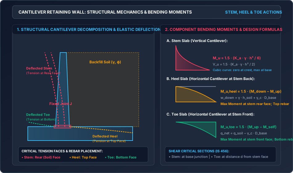
  1. Vertical Stem: A vertical cantilever slab fixed at its junction with the base slab, resisting lateral active earth pressure from the backfill. Bending creates tension at the rear (soil) face, requiring vertical flexural reinforcement anchored securely into the base foundation.
  2. Heel Slab: A horizontal cantilever projecting behind the stem, supporting the heavy overburden of backfill soil and its own dead weight against the upward bearing reaction of the subgrade. Net downward loading causes the heel to deflect downwards, creating tension at its top face, requiring primary longitudinal reinforcement placed along the upper surface.
  3. Toe Slab: A horizontal cantilever projecting in front of the stem, subjected to high upward subgrade reaction stresses partially counteracted by the slab's self-weight. Net upward pressure causes the toe to deflect upwards, creating tension at its bottom face, requiring primary flexural reinforcement placed along the lower surface.

This master topic establishes the structural limit state design methodologies per IS 456:2000, derives the governing moments, shears, and curtailment laws, demonstrates step-by-step reinforcement detailing per SP 34, and provides three fully verified numerical design problems.


2. Governing Principles & Theoretical Foundations

                           Stem Crest (Min 150-200 mm)
                                   ┌───┐
                                   │   │
                                   │   │ ◄─── Granular Backfill (γ, φ)
                                   │   │      Active Earth Pressure
                                   │   │      pa(y) = Ka * γ * y
                         Stem      │   │
                         Slab      │   │
                                   │   │
       Natural Ground              │   │
             ▼                     │   │
     ═════════════                 │   │
     Toe Projection                │   │      Virtual Vertical Plane
          ┌────────────────────────┘   └────────────────────────┐
          │                                                     │
          │                   BASE SLAB (Thickness D)           │
          └────────────────────────┬───┬────────────────────────┘
                                   └───┘
                                 Shear Key
            ◄─────── b_toe ───────►◄─t─►◄─────── b_heel ───────►
            ◄─────────────────────── B ────────────────────────►

2.1 Proportioning Guidelines for Cantilever Walls

To initiate structural design, empirical rules derived from geotechnical equilibrium are used to determine initial trial dimensions:

  1. Total Height (HH): H=h+DfH = h + D_f Where hh is the clear height of earth to be retained above ground level, and DfD_f is the minimum foundation depth given by Rankine's formula: Df=qaγ(1−sin⁡ϕ1+sin⁡ϕ)2D_f = \frac{q_a}{\gamma} \left(\frac{1 - \sin\phi}{1 + \sin\phi}\right)^2
  2. Base Slab Width (BB): B≈0.40H to 0.70H(Typically 0.50H to 0.60H for level backfill)B \approx 0.40 H \text{ to } 0.70 H \quad (\text{Typically } 0.50 H \text{ to } 0.60 H \text{ for level backfill})
  3. Toe Projection (btoeb_{\text{toe}}): btoe≈13B to 14Bb_{\text{toe}} \approx \frac{1}{3} B \text{ to } \frac{1}{4} B
  4. Base Slab Thickness (DbaseD_{\text{base}}): Dbase≈110H to 112H(Minimum 300 mm to 450 mm)D_{\text{base}} \approx \frac{1}{10} H \text{ to } \frac{1}{12} H \quad (\text{Minimum } 300\text{ mm to } 450\text{ mm})
  5. Stem Base Thickness (tbott_{\text{bot}}): Equal to or slightly less than base slab thickness DbaseD_{\text{base}}, verified by maximum flexural cantilever moment and shear stress.
  6. Stem Top Thickness (ttopt_{\text{top}}): Minimum 150 mm150\text{ mm} (preferably 200 mm200\text{ mm}) to accommodate double-layer reinforcement, internal weepholes, and concrete vibration needles.

3. Mathematical Derivations & Analytical Formulations

3.1 Design of the Vertical Stem

The stem functions as a vertical cantilever slab fixed at the base junction (y=0y = 0 at top of base slab, y=hy = h at crest).

  • Service Lateral Thrust at Base (y=0y = 0): Pa=12Kaγh2P_a = \frac{1}{2} K_a \gamma h^2
  • Service Bending Moment at Base: M=Pa×(h3)=16Kaγh3M = P_a \times \left(\frac{h}{3}\right) = \frac{1}{6} K_a \gamma h^3
  • Factored Design Bending Moment (MuM_u): Per IS 456 (Table 18, Load factor γf=1.5\gamma_f = 1.5): Mu=1.50×(16Kaγh3)=0.25Kaγh3M_u = 1.50 \times \left(\frac{1}{6} K_a \gamma h^3\right) = 0.25 K_a \gamma h^3
  • Factored Design Shear Force (VuV_u): Vu=1.50×(12Kaγh2)=0.75Kaγh2V_u = 1.50 \times \left(\frac{1}{2} K_a \gamma h^2\right) = 0.75 K_a \gamma h^2
Required Effective Depth (dd):

Equating MuM_u to the limiting moment of resistance (Mu,lim⁡M_{u,\lim}) for a balanced section:

Mu,lim⁡=Ru,max⁡bd2M_{u,\lim} = R_{u,\max} b d^2

Where Ru,max⁡=0.36fckxu,max⁡d(1−0.416xu,max⁡d)R_{u,\max} = 0.36 f_{ck} \frac{x_{u,\max}}{d}\left(1 - 0.416 \frac{x_{u,\max}}{d}\right):

  • For Fe 250: Ru,max⁡=0.148fckR_{u,\max} = 0.148 f_{ck}
  • For Fe 415: Ru,max⁡=0.138fckR_{u,\max} = 0.138 f_{ck}
  • For Fe 500: Ru,max⁡=0.133fckR_{u,\max} = 0.133 f_{ck}

For a unit width strip (b=1000 mmb = 1000\text{ mm}):

dreq=MuRu,max⁡bd_{\text{req}} = \sqrt{\frac{M_u}{R_{u,\max} b}}
Tension Reinforcement (AstA_{st}):

From the quadratic flexure equation:

Mu=0.87fyAstd(1−Astfybdfck)M_u = 0.87 f_y A_{st} d \left(1 - \frac{A_{st} f_y}{b d f_{ck}}\right) Ast=0.5fckfy[1−1−4.6Mufckbd2]bdA_{st} = \frac{0.5 f_{ck}}{f_y} \left[ 1 - \sqrt{1 - \frac{4.6 M_u}{f_{ck} b d^2}} \right] b d
Curtailment of Stem Reinforcement:

Because the bending moment in the cantilever stem decreases cubically from the base to the top (Mu(z)∝z3M_u(z) \propto z^3, where z=h−yz = h - y is the depth from the crest), continuing all main vertical reinforcement to the top is highly uneconomical.

  • Let 50%50\% of the vertical bars be curtailed at height y1y_1 from the base.
  • Theoretical cut-off point occurs where the moment capacity of 50%50\% steel equals the factored moment: Mu(y1)=0.50Mu,baseM_u(y_1) = 0.50 M_{u,\text{base}} 16Kaγ(h−y1)3=0.50(16Kaγh3)\frac{1}{6} K_a \gamma (h - y_1)^3 = 0.50 \left(\frac{1}{6} K_a \gamma h^3\right) (h−y1)3=0.50h3  ⟹  h−y1=h23≈0.7937h(h - y_1)^3 = 0.50 h^3 \implies h - y_1 = \frac{h}{\sqrt[3]{2}} \approx 0.7937 h y1,theo=h(1−123)≈0.2063hy_{1,\text{theo}} = h \left(1 - \frac{1}{\sqrt[3]{2}}\right) \approx 0.2063 h
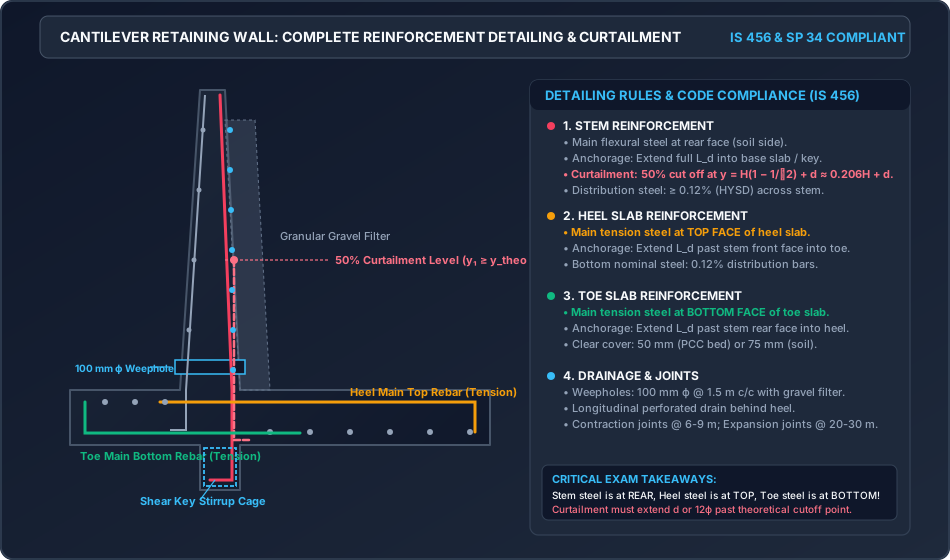
  • Actual Curtailment Level (IS 456 Cl. 26.2.3.1): Bars must extend beyond the theoretical cut-off point by a distance equal to the effective depth dd or 12ϕ12\phi, whichever is greater: y1,actual=y1,theo+max⁡(d,12ϕ)y_{1,\text{actual}} = y_{1,\text{theo}} + \max(d, 12\phi)

3.2 Design of the Heel Slab

The heel slab acts as a horizontal cantilever projecting behind the stem, fixed at the stem rear face.

  • Downward Pressures:
    1. Soil overburden: wsoil=γhsoilw_{\text{soil}} = \gamma h_{\text{soil}}
    2. Slab self-weight: wslab=γcDbasew_{\text{slab}} = \gamma_c D_{\text{base}} Total downward pressure: wdown=wsoil+wslabw_{\text{down}} = w_{\text{soil}} + w_{\text{slab}}
  • Upward Pressure: Linear subgrade soil reaction varying from qstem,rearq_{\text{stem,rear}} at the junction to qheel,tipq_{\text{heel,tip}} at the outer heel edge.
  • Net Upward Soil Up-thrust: Rup=qstem,rear+qheel,tip2⋅bheelR_{\text{up}} = \frac{q_{\text{stem,rear}} + q_{\text{heel,tip}}}{2} \cdot b_{\text{heel}} Acting at distance xˉup\bar{x}_{\text{up}} from the stem rear face.
  • Net Factored Bending Moment at Stem Rear Face (Mu,heelM_{u,\text{heel}}): Mdown=wdownbheel22M_{\text{down}} = w_{\text{down}} \frac{b_{\text{heel}}^2}{2} Mnet=Mdown−RupxˉupM_{\text{net}} = M_{\text{down}} - R_{\text{up}} \bar{x}_{\text{up}} Mu,heel=1.50×Mnet(Hogging moment, tension at top)M_{u,\text{heel}} = 1.50 \times M_{\text{net}} \quad (\text{Hogging moment, tension at top})
  • Primary Steel Placement: Main flexural tension steel is placed along the TOP FACE of the heel slab and anchored past the stem junction with full development length LdL_d.

3.3 Design of the Toe Slab

The toe slab acts as a horizontal cantilever projecting in front of the stem, fixed at the stem front face.

  • Upward Pressure: Linear soil reaction varying from qtoe,tipq_{\text{toe,tip}} at the extreme toe edge to qstem,frontq_{\text{stem,front}} at the stem front face.
  • Downward Pressure: Self-weight of toe slab: wself=γcDbasew_{\text{self}} = \gamma_c D_{\text{base}}.
  • Net Service Bending Moment at Stem Front Face (MtoeM_{\text{toe}}): Mtoe=∫0btoe[q(x)−wself]x dxM_{\text{toe}} = \int_0^{b_{\text{toe}}} [q(x) - w_{\text{self}}] x \, dx Mu,toe=1.50×Mtoe(Sagging moment, tension at bottom)M_{u,\text{toe}} = 1.50 \times M_{\text{toe}} \quad (\text{Sagging moment, tension at bottom})
  • Primary Steel Placement: Main flexural tension steel is placed along the BOTTOM FACE of the toe slab and anchored past the stem into the heel slab.
  • Critical Section for Shear in Toe: Per IS 456 Clause 34.2.4.1(a), the critical section for wide-beam shear is located at a distance dd from the front face of the stem. τv=Vu,dbd≤τc\tau_v = \frac{V_{u,d}}{b d} \le \tau_c

4. Indian Standard Code Provisions (IS 456:2000, SP 16, SP 34)

4.1 Minimum Reinforcement Requirements

  1. Vertical and Horizontal Distribution Steel (Clause 26.5.2.1):
    • For High Yield Strength Deformed (HYSD) bars (Fe 415 / Fe 500): Ast,min⁡=0.12% of gross cross-sectional area (0.0012bD)A_{st,\min} = 0.12\% \text{ of gross cross-sectional area } (0.0012 b D)
    • For Mild Steel (Fe 250): Ast,min⁡=0.15% of gross cross-sectional area (0.0015bD)A_{st,\min} = 0.15\% \text{ of gross cross-sectional area } (0.0015 b D)
    • Temperature and shrinkage steel is distributed uniformly across both faces.
  2. Maximum Bar Spacing (Clause 26.3.3):
    • Main bars: ≤3d\le 3d or 300 mm300\text{ mm}, whichever is smaller.
    • Distribution bars: ≤5d\le 5d or 450 mm450\text{ mm}, whichever is smaller.

4.2 Anchorage and Development Length (LdL_d)

Per Clause 26.2.1:

Ld=ϕσs4τbd=0.87fyϕ4(1.6τbd,plain)L_d = \frac{\phi \sigma_s}{4 \tau_{bd}} = \frac{0.87 f_y \phi}{4 (1.6 \tau_{bd,\text{plain}})}
  • For M25 concrete and Fe 415 steel: τbd=1.4×1.6=2.24 N/mm2  ⟹  Ld=0.87×4154×2.24ϕ≈40.3ϕ\tau_{bd} = 1.4 \times 1.6 = 2.24\text{ N/mm}^2 \implies L_d = \frac{0.87 \times 415}{4 \times 2.24} \phi \approx 40.3 \phi.
  • For M25 concrete and Fe 500 steel: Ld≈47.0ϕL_d \approx 47.0 \phi.
  • All stem vertical bars must be extended into the base slab / shear key by at least LdL_d beyond the junction.

4.3 Permissible Shear Stress (τc\tau_c)

Per Clause 40.2 and Table 19 of IS 456:

  • Nominal shear stress: τv=Vubd\tau_v = \frac{V_u}{b d}.
  • In slabs and retaining wall stems, design shear strength τc\tau_c should exceed τv\tau_v without requiring shear stirrups, because providing stirrups in thin slabs is practically difficult.
  • If τv>τc\tau_v > \tau_c, increase the slab thickness (DD) rather than providing shear reinforcement.

5. Comprehensive Engineering Diagrams & Structural Cross-Sections

5.1 Cantilever Retaining Wall Structural Action & Moments

The diagram below illustrates the structural actions, deflected shapes, fixed joint conditions, and bending moment diagrams for the stem, heel, and toe cantilevers.

Cantilever Retaining Wall Structural Action and Bending Moments

5.2 Complete Reinforcement Detailing & Curtailment (SP 34)

The diagram below provides the comprehensive structural detailing cross-section, including main steel at rear, top, and bottom faces, 50% stem curtailment elevation, shear key reinforcement, weepholes, and granular filters.

Cantilever Retaining Wall Reinforcement Detailing and Curtailment

6. Solved Numerical Examples

Example 1: Comprehensive Structural Design of Vertical Stem with Rebar Curtailment

Problem Statement: A cantilever retaining wall retains backfill soil of height h=4.80 mh = 4.80\text{ m} above the base slab. The backfill soil has unit weight γ=18.0 kN/m3\gamma = 18.0\text{ kN/m}^3 and angle of internal friction ϕ=30∘\phi = 30^\circ. Design the vertical stem using M25 grade concrete and Fe 415 steel.

  1. Determine the design factored bending moment MuM_u and shear force VuV_u at the base of the stem.
  2. Determine the required effective depth for flexure and adopt a practical stem base thickness.
  3. Calculate the required flexural tension steel (AstA_{st}) and determine the spacing for 16 mmϕ16\text{ mm}\phi bars.
  4. Verify the nominal shear stress against τc\tau_c (IS 456 Table 19).
  5. Determine the theoretical and actual curtailment height for cutting off 50%50\% of the vertical reinforcement.

Solution: Step 1: Lateral Earth Pressure and Factored Actions:

Ka=1−sin⁡30∘1+sin⁡30∘=13K_a = \frac{1 - \sin 30^\circ}{1 + \sin 30^\circ} = \frac{1}{3}

Service active earth thrust on stem:

Pa=12Kaγh2=12×13×18.0×(4.80)2=3.0×23.04=69.12 kN/mP_a = \frac{1}{2} K_a \gamma h^2 = \frac{1}{2} \times \frac{1}{3} \times 18.0 \times (4.80)^2 = 3.0 \times 23.04 = 69.12\text{ kN/m}

Height of action above stem base:

zˉ=h3=4.803=1.60 m\bar{z} = \frac{h}{3} = \frac{4.80}{3} = 1.60\text{ m}

Service bending moment at stem base:

M=Pa×zˉ=69.12×1.60=110.592 kNm/mM = P_a \times \bar{z} = 69.12 \times 1.60 = 110.592\text{ kNm/m}

Factored design actions (γf=1.5\gamma_f = 1.5):

Mu=1.50×110.592=165.888 kNm/mM_u = 1.50 \times 110.592 = 165.888\text{ kNm/m} Vu=1.50×69.12=103.68 kN/mV_u = 1.50 \times 69.12 = 103.68\text{ kN/m}

Step 2: Effective Depth and Stem Thickness: For M25 concrete and Fe 415 steel:

Ru,max⁡=0.138fck=0.138×25.0=3.45 N/mm2R_{u,\max} = 0.138 f_{ck} = 0.138 \times 25.0 = 3.45\text{ N/mm}^2

For a 1.0 m1.0\text{ m} strip (b=1000 mmb = 1000\text{ mm}):

dreq=Mu×106Ru,max⁡b=165.888×1063.45×1000=48083.5=219.28 mmd_{\text{req}} = \sqrt{\frac{M_u \times 10^6}{R_{u,\max} b}} = \sqrt{\frac{165.888 \times 10^6}{3.45 \times 1000}} = \sqrt{48083.5} = 219.28\text{ mm}

To satisfy deflection serviceability and avoid shear stirrups, adopt an overall stem base thickness:

Dbot=400 mmD_{\text{bot}} = 400\text{ mm}

With clear cover =50 mm= 50\text{ mm} and bar diameter ϕ=16 mm\phi = 16\text{ mm}:

dprov=400−50−162=342.0 mm(≫219.3 mm, Section is under-reinforced)d_{\text{prov}} = 400 - 50 - \frac{16}{2} = 342.0\text{ mm} \quad (\gg 219.3\text{ mm, Section is under-reinforced})

Adopt stem top thickness ttop=200 mmt_{\text{top}} = 200\text{ mm}.

Step 3: Flexural Tension Reinforcement (AstA_{st}): From the quadratic limit state equation:

Ast=0.5×25415[1−1−4.6×165.888×10625×1000×(342)2]×1000×342A_{st} = \frac{0.5 \times 25}{415} \left[ 1 - \sqrt{1 - \frac{4.6 \times 165.888 \times 10^6}{25 \times 1000 \times (342)^2}} \right] \times 1000 \times 342 Ast=0.03012×[1−1−0.26085]×342000=0.03012×[1−0.85974]×342000A_{st} = 0.03012 \times [1 - \sqrt{1 - 0.26085}] \times 342000 = 0.03012 \times [1 - 0.85974] \times 342000 Ast,req=1444.77 mm2/mA_{st,\text{req}} = 1444.77\text{ mm}^2\text{/m}

Minimum steel:

Ast,min⁡=0.0012×1000×400=480.0 mm2/m<1444.77 mm2/m[OK]A_{st,\min} = 0.0012 \times 1000 \times 400 = 480.0\text{ mm}^2\text{/m} < 1444.77\text{ mm}^2\text{/m} \quad \text{[OK]}

Using 16 mmϕ16\text{ mm}\phi bars (ab=201.06 mm2a_b = 201.06\text{ mm}^2):

Spacing s=1000×201.061444.77=139.16 mm\text{Spacing } s = \frac{1000 \times 201.06}{1444.77} = 139.16\text{ mm}

Provide 16 mmϕ16\text{ mm}\phi bars @ 130 mm130\text{ mm} c/c (Ast,prov=1546.6 mm2/mA_{st,\text{prov}} = 1546.6\text{ mm}^2\text{/m}). Reinforcement percentage:

pt=1546.61000×342×100=0.452%p_t = \frac{1546.6}{1000 \times 342} \times 100 = 0.452\%

Step 4: Shear Stress Check at Base:

τv=Vu×103bd=103.68×1031000×342=0.303 N/mm2\tau_v = \frac{V_u \times 10^3}{b d} = \frac{103.68 \times 10^3}{1000 \times 342} = 0.303\text{ N/mm}^2

From IS 456 Table 19 for M25 concrete and pt=0.45%p_t = 0.45\%:

τc=0.464 N/mm2\tau_c = 0.464\text{ N/mm}^2

Since τv=0.303 N/mm2≤τc=0.464 N/mm2\tau_v = 0.303\text{ N/mm}^2 \le \tau_c = 0.464\text{ N/mm}^2, the stem is fully safe in shear without shear reinforcement.

Step 5: Curtailment of 50% Vertical Steel: Theoretical height y1,theoy_{1,\text{theo}} where moment capacity drops to 50%50\%:

y1,theo=h(1−123)=4.80×(1−0.7937)=0.990 m from basey_{1,\text{theo}} = h \left(1 - \frac{1}{\sqrt[3]{2}}\right) = 4.80 \times (1 - 0.7937) = 0.990\text{ m from base}

Extension required beyond theoretical cutoff (Cl. 26.2.3.1):

Δ=max⁡(d,12ϕ)=max⁡(0.342 m,12×0.016 m)=0.342 m\Delta = \max(d, 12\phi) = \max(0.342\text{ m}, 12 \times 0.016\text{ m}) = 0.342\text{ m}

Actual cut-off level above base:

y1,actual=0.990+0.342=1.332 my_{1,\text{actual}} = 0.990 + 0.342 = 1.332\text{ m}

Adopt cut-off for alternate bars (50% steel) at 1.40 m1.40\text{ m} above the base slab. The remaining 50% (16 mmϕ16\text{ mm}\phi @ 260 mm260\text{ mm} c/c) continue to the top of the stem.


Example 2: Structural Design of the Heel Slab

Problem Statement: For the retaining wall designed in Example 1, the base slab has a thickness Dbase=450 mmD_{\text{base}} = 450\text{ mm} (d=392 mmd = 392\text{ mm}) and heel projection bheel=2.00 mb_{\text{heel}} = 2.00\text{ m}. The height of soil overburden is 4.80 m4.80\text{ m} (γ=18.0 kN/m3\gamma = 18.0\text{ kN/m}^3). From stability analysis, the upward soil reaction under the heel slab varies linearly from qstem,rear=70.0 kPaq_{\text{stem,rear}} = 70.0\text{ kPa} at the stem rear face to qheel,tip=40.0 kPaq_{\text{heel,tip}} = 40.0\text{ kPa} at the heel outer edge. Design the flexural tension reinforcement and verify the shear stress for the heel slab using M25 concrete and Fe 415 steel.

Solution: Step 1: Downward and Upward Load Components on Heel:

  • Soil weight: wsoil=4.80×18.0=86.40 kPaw_{\text{soil}} = 4.80 \times 18.0 = 86.40\text{ kPa}
  • Slab self-weight: wslab=0.45×25.0=11.25 kPaw_{\text{slab}} = 0.45 \times 25.0 = 11.25\text{ kPa}
  • Total downward pressure: wdown=86.40+11.25=97.65 kPaw_{\text{down}} = 86.40 + 11.25 = 97.65\text{ kPa}

Downward cantilever action about stem rear face:

Wdown=wdown×bheel=97.65×2.00=195.30 kN/mW_{\text{down}} = w_{\text{down}} \times b_{\text{heel}} = 97.65 \times 2.00 = 195.30\text{ kN/m} Mdown=Wdown×bheel2=195.30×1.00=195.30 kNm/mM_{\text{down}} = W_{\text{down}} \times \frac{b_{\text{heel}}}{2} = 195.30 \times 1.00 = 195.30\text{ kNm/m}

Upward soil reaction about stem rear face:

Rup=70.0+40.02×2.00=110.00 kN/mR_{\text{up}} = \frac{70.0 + 40.0}{2} \times 2.00 = 110.00\text{ kN/m}

Centroid from stem rear face:

xˉup=bheel3(qstem+2qtipqstem+qtip)=2.003×(70.0+2×40.070.0+40.0)=2.003×150.0110.0=0.909 m\bar{x}_{\text{up}} = \frac{b_{\text{heel}}}{3} \left(\frac{q_{\text{stem}} + 2 q_{\text{tip}}}{q_{\text{stem}} + q_{\text{tip}}}\right) = \frac{2.00}{3} \times \left(\frac{70.0 + 2 \times 40.0}{70.0 + 40.0}\right) = \frac{2.00}{3} \times \frac{150.0}{110.0} = 0.909\text{ m} Mup=Rup×xˉup=110.00×0.909=100.00 kNm/mM_{\text{up}} = R_{\text{up}} \times \bar{x}_{\text{up}} = 110.00 \times 0.909 = 100.00\text{ kNm/m}

Step 2: Net Factored Design Actions at Stem Rear Face:

Mnet,service=Mdown−Mup=195.30−100.00=95.30 kNm/m(Hogging)M_{\text{net,service}} = M_{\text{down}} - M_{\text{up}} = 195.30 - 100.00 = 95.30\text{ kNm/m} \quad (\text{Hogging}) Vnet,service=Wdown−Rup=195.30−110.00=85.30 kN/mV_{\text{net,service}} = W_{\text{down}} - R_{\text{up}} = 195.30 - 110.00 = 85.30\text{ kN/m}

Factored actions:

Mu,heel=1.50×95.30=142.95 kNm/mM_{u,\text{heel}} = 1.50 \times 95.30 = 142.95\text{ kNm/m} Vu,heel=1.50×85.30=127.95 kN/mV_{u,\text{heel}} = 1.50 \times 85.30 = 127.95\text{ kN/m}

Step 3: Flexural Reinforcement (Top Face of Heel): Effective depth: dheel=450−50−8=392 mmd_{\text{heel}} = 450 - 50 - 8 = 392\text{ mm}.

Ast=0.5×25415[1−1−4.6×142.95×10625×1000×(392)2]×1000×392A_{st} = \frac{0.5 \times 25}{415} \left[ 1 - \sqrt{1 - \frac{4.6 \times 142.95 \times 10^6}{25 \times 1000 \times (392)^2}} \right] \times 1000 \times 392 Ast=0.03012×[1−1−0.17117]×392000=0.03012×[1−0.91040]×392000A_{st} = 0.03012 \times [1 - \sqrt{1 - 0.17117}] \times 392000 = 0.03012 \times [1 - 0.91040] \times 392000 Ast,req=1057.37 mm2/mA_{st,\text{req}} = 1057.37\text{ mm}^2\text{/m}

Using 16 mmϕ16\text{ mm}\phi bars (ab=201.06 mm2a_b = 201.06\text{ mm}^2):

Spacing s=1000×201.061057.37=190.15 mm\text{Spacing } s = \frac{1000 \times 201.06}{1057.37} = 190.15\text{ mm}

Provide 16 mmϕ16\text{ mm}\phi bars @ 150 mm150\text{ mm} c/c at the TOP FACE of the heel slab (Ast,prov=1340.4 mm2/mA_{st,\text{prov}} = 1340.4\text{ mm}^2\text{/m}).

pt=1340.41000×392×100=0.342%p_t = \frac{1340.4}{1000 \times 392} \times 100 = 0.342\%

Step 4: Shear Stress Check at Stem Face:

τv=Vu,heel×103bd=127.95×1031000×392=0.326 N/mm2\tau_v = \frac{V_{u,\text{heel}} \times 10^3}{b d} = \frac{127.95 \times 10^3}{1000 \times 392} = 0.326\text{ N/mm}^2

From IS 456 Table 19 for M25 concrete and pt=0.34%p_t = 0.34\%:

τc=0.400 N/mm2\tau_c = 0.400\text{ N/mm}^2

Since τv=0.326 N/mm2≤τc=0.400 N/mm2\tau_v = 0.326\text{ N/mm}^2 \le \tau_c = 0.400\text{ N/mm}^2, the heel slab is SAFE in shear.


Example 3: Structural Design of the Toe Slab

Problem Statement: For the same retaining wall, the toe slab has projection btoe=1.00 mb_{\text{toe}} = 1.00\text{ m} and thickness Dbase=450 mmD_{\text{base}} = 450\text{ mm} (d=392 mmd = 392\text{ mm}). The upward soil bearing reaction under the toe varies from qtoe,tip=140.0 kPaq_{\text{toe,tip}} = 140.0\text{ kPa} at the toe edge to qstem,front=110.0 kPaq_{\text{stem,front}} = 110.0\text{ kPa} at the front face of the stem. Design the bottom flexural reinforcement and perform the wide-beam shear check at the critical section located at distance dd from the front face of the stem.

Solution: Step 1: Net Upward Pressure on Toe:

  • Downward self-weight: wself=0.45×25.0=11.25 kPaw_{\text{self}} = 0.45 \times 25.0 = 11.25\text{ kPa}
  • Net upward pressure at toe tip: pnet,tip=140.0−11.25=128.75 kPap_{\text{net,tip}} = 140.0 - 11.25 = 128.75\text{ kPa}
  • Net upward pressure at stem front face: pnet,stem=110.0−11.25=98.75 kPap_{\text{net,stem}} = 110.0 - 11.25 = 98.75\text{ kPa}

Step 2: Service and Factored Bending Moment at Stem Front Face: Total upward shear force at stem face:

Vservice=128.75+98.752×1.00=113.75 kN/mV_{\text{service}} = \frac{128.75 + 98.75}{2} \times 1.00 = 113.75\text{ kN/m}

Centroid from stem front face:

xˉ=1.003(98.75+2×128.7598.75+128.75)=1.003×356.25227.50=0.522 m\bar{x} = \frac{1.00}{3} \left(\frac{98.75 + 2 \times 128.75}{98.75 + 128.75}\right) = \frac{1.00}{3} \times \frac{356.25}{227.50} = 0.522\text{ m}

Service moment:

M=Vservice×xˉ=113.75×0.522=59.38 kNm/m(Sagging)M = V_{\text{service}} \times \bar{x} = 113.75 \times 0.522 = 59.38\text{ kNm/m} \quad (\text{Sagging})

Factored actions:

Mu,toe=1.50×59.38=89.06 kNm/mM_{u,\text{toe}} = 1.50 \times 59.38 = 89.06\text{ kNm/m} Vu,toe=1.50×113.75=170.62 kN/mV_{u,\text{toe}} = 1.50 \times 113.75 = 170.62\text{ kN/m}

Step 3: Flexural Reinforcement (Bottom Face of Toe):

Ast=0.5×25415[1−1−4.6×89.06×10625×1000×(392)2]×1000×392A_{st} = \frac{0.5 \times 25}{415} \left[ 1 - \sqrt{1 - \frac{4.6 \times 89.06 \times 10^6}{25 \times 1000 \times (392)^2}} \right] \times 1000 \times 392 Ast=0.03012×[1−1−0.10664]×392000=0.03012×[1−0.94518]×392000A_{st} = 0.03012 \times [1 - \sqrt{1 - 0.10664}] \times 392000 = 0.03012 \times [1 - 0.94518] \times 392000 Ast,req=647.00 mm2/mA_{st,\text{req}} = 647.00\text{ mm}^2\text{/m}

Using 16 mmϕ16\text{ mm}\phi bars (ab=201.06 mm2a_b = 201.06\text{ mm}^2):

Spacing s=1000×201.06647.00=310.7 mm\text{Spacing } s = \frac{1000 \times 201.06}{647.00} = 310.7\text{ mm}

Per IS 456, maximum spacing =3d=3×392=1176 mm= 3d = 3 \times 392 = 1176\text{ mm} or 300 mm300\text{ mm}. Provide 16 mmϕ16\text{ mm}\phi bars @ 200 mm200\text{ mm} c/c at the BOTTOM FACE of the toe slab (Ast,prov=1005.3 mm2/mA_{st,\text{prov}} = 1005.3\text{ mm}^2\text{/m}).

pt=1005.31000×392×100=0.256%p_t = \frac{1005.3}{1000 \times 392} \times 100 = 0.256\%

Step 4: Wide-Beam Shear Check at Critical Section (dd from stem face): Distance of critical section from the outer toe tip:

xcrit=btoe−d=1.00−0.392=0.608 mx_{\text{crit}} = b_{\text{toe}} - d = 1.00 - 0.392 = 0.608\text{ m}

Net pressure at the critical section (linear interpolation):

pnet,crit=128.75−(128.75−98.75)×(0.6081.00)=128.75−30.0×0.608=110.51 kPap_{\text{net,crit}} = 128.75 - (128.75 - 98.75) \times \left(\frac{0.608}{1.00}\right) = 128.75 - 30.0 \times 0.608 = 110.51\text{ kPa}

Service shear force at critical section:

Vcrit=128.75+110.512×0.608=119.63×0.608=72.73 kN/mV_{\text{crit}} = \frac{128.75 + 110.51}{2} \times 0.608 = 119.63 \times 0.608 = 72.73\text{ kN/m}

Factored shear force:

Vu,crit=1.50×72.73=109.10 kN/mV_{u,\text{crit}} = 1.50 \times 72.73 = 109.10\text{ kN/m}

Nominal shear stress:

τv=Vu,crit×103bd=109.10×1031000×392=0.278 N/mm2\tau_v = \frac{V_{u,\text{crit}} \times 10^3}{b d} = \frac{109.10 \times 10^3}{1000 \times 392} = 0.278\text{ N/mm}^2

From IS 456 Table 19 for M25 concrete and pt=0.26%p_t = 0.26\%:

τc=0.350 N/mm2\tau_c = 0.350\text{ N/mm}^2

Since τv=0.278 N/mm2≤τc=0.350 N/mm2\tau_v = 0.278\text{ N/mm}^2 \le \tau_c = 0.350\text{ N/mm}^2, the toe slab is COMPLETELY SAFE in shear.


7. Common Pitfalls, Misconceptions & Exam Traps

  1. Rebar Placement Confusion (The #1 Retaining Wall Trap):
    • Stem: Main steel is at the REAR FACE (in contact with retained backfill).
    • Heel: Main steel is at the TOP FACE (because downward soil weight dominates).
    • Toe: Main steel is at the BOTTOM FACE (because upward soil pressure dominates).
    • Exam Trap: Placing heel reinforcement at the bottom face will lead to catastrophic tensile rupture and wall failure.
  2. Curtailment Extension Rule (dd or 12ϕ12\phi):
    • Mistake: Cutting off stem bars exactly at the theoretical height y1,theo≈0.206hy_{1,\text{theo}} \approx 0.206 h.
    • Code Mandate: Per IS 456 Cl. 26.2.3.1, bars must continue past the theoretical cutoff by max⁡(d,12ϕ)\max(d, 12\phi). Omitting this extension causes premature shear-flexure diagonal tension cracking.
  3. Critical Section for Toe Shear vs Stem Shear:
    • Stem: Critical shear section is at the junction with the base slab (y=0y = 0).
    • Toe: Critical shear section is at distance dd from the front face of the stem.
  4. Distribution Reinforcement Direction:
    • Horizontal bars in the stem are distribution/shrinkage steel (0.12%0.12\%), while vertical bars are main structural steel. In a one-way slab, main steel spans the short direction; in a retaining wall stem, the vertical height is the cantilever span!

8. Comparative Analysis & Summary Matrices

Component Structural Design Parameters

Parameter Vertical Stem Heel Slab Toe Slab
Span Direction Vertical Cantilever Horizontal Cantilever Horizontal Cantilever
Fixed Boundary Top of base slab Rear face of stem Front face of stem
Dominant Loading Lateral active earth pressure Downward soil & slab weight Upward soil contact pressure
Bending Moment Sense Tension at Rear Face Tension at Top Face Tension at Bottom Face
Main Steel Location Vertical rebar along rear face Longitudinal rebar at top face Longitudinal rebar at bottom face
Shear Critical Plane Base junction (y=0y = 0) Stem rear face Distance dd from stem front face
Minimum Steel 0.12%0.12\% HYSD (0.15%0.15\% Mild) 0.12%0.12\% HYSD (0.15%0.15\% Mild) 0.12%0.12\% HYSD (0.15%0.15\% Mild)

9. Practical Design & Detailing Guidelines

  1. Stem Front Face Taper:
    • Provide a front face batter of 1 in 481\text{ in }48 to 1 in 241\text{ in }24 so that the wall appears truly vertical after under-load cantilever rotation.
  2. Transverse Dowels and Shear Key Detailing:
    • Extend vertical stem bars into the sub-base shear key to provide rigid monolithic anchorage.
    • Provide closed stirrups in the shear key (≥8 mmϕ\ge 8\text{ mm}\phi @ 200 mm200\text{ mm} c/c) to resist passive thrust shear.
  3. Weepholes and Filtering:
    • Install 100 mmϕ100\text{ mm}\phi PVC weepholes with a minimum slope of 1:201:20 towards the front.
    • Enclose the back of weepholes with 0.1 m30.1\text{ m}^3 of graded gravel wrapped in non-woven geotextile to prevent soil migration.

GATE Civil Engineering

  • Frequent Problems:
    • Factored cantilever moment at the base of the stem: Mu=1.5(Kaγh36)M_u = 1.5 \left(\frac{K_a \gamma h^3}{6}\right).
    • Identification of tension fibers: Stem (rear), Heel (top), Toe (bottom).
    • Theoretical curtailment calculation for 50%50\% cut-off (y=h(1−1/23)y = h(1 - 1/\sqrt[3]{2})).

UPSC ESE (Engineering Services)

  • Frequent Problems:
    • Complete 20-mark design question: Proportioning stem, heel, and toe, designing flexural steel, and sketching SP 34 cross-sectional reinforcement details.
    • Critical shear calculation in the toe slab at distance dd from stem face.

SSC JE & State AE/JE

  • Frequent Problems:
    • Value of minimum steel in stem (0.12%0.12\% for HYSD).
    • Maximum spacing of distribution bars (5d5d or 450 mm450\text{ mm}).
    • Location of critical shear plane in toe slab (dd from column/stem face).

11. Key Formula Sheet & Quick Revision Memory Aid

Mu,stem=1.50×Kaγh36=0.25Kaγh3Vu,stem=1.50×Kaγh22=0.75Kaγh2dreq=MuRu,max⁡by1,theo=h(1−123)≈0.206hy1,actual=y1,theo+max⁡(d,12ϕ)Mu,heel=1.50[wdownbheel22−Rupxˉup](Top Tension)Mu,toe=1.50[∫0btoe[q(x)−wself]x dx](Bottom Tension)Vu,toe,crit=Factored net shear at distance d from front faceAst,min⁡=0.0012bD(HYSD Fe 415 / Fe 500)\begin{aligned} M_{u,\text{stem}} &= 1.50 \times \frac{K_a \gamma h^3}{6} = 0.25 K_a \gamma h^3 \\ V_{u,\text{stem}} &= 1.50 \times \frac{K_a \gamma h^2}{2} = 0.75 K_a \gamma h^2 \\ d_{\text{req}} &= \sqrt{\frac{M_u}{R_{u,\max} b}} \\ y_{1,\text{theo}} &= h \left(1 - \frac{1}{\sqrt[3]{2}}\right) \approx 0.206 h \\ y_{1,\text{actual}} &= y_{1,\text{theo}} + \max(d, 12\phi) \\ M_{u,\text{heel}} &= 1.50 \left[ w_{\text{down}} \frac{b_{\text{heel}}^2}{2} - R_{\text{up}} \bar{x}_{\text{up}} \right] \quad (\text{Top Tension}) \\ M_{u,\text{toe}} &= 1.50 \left[ \int_0^{b_{\text{toe}}} [q(x) - w_{\text{self}}] x \, dx \right] \quad (\text{Bottom Tension}) \\ V_{u,\text{toe,crit}} &= \text{Factored net shear at distance } d \text{ from front face} \\ A_{st,\min} &= 0.0012 b D \quad (\text{HYSD Fe 415 / Fe 500}) \end{aligned}

12. Comprehensive Verification, References & Peer Review Log

  1. Standard Specifications:
    • IS 456:2000: Plain and Reinforced Concrete — Code of Practice (Clauses 26.2, 26.3, 26.5.2, 34.2, 40, Table 19).
    • SP 16:1980: Design Aids for Reinforced Concrete to IS 456.
    • SP 34:1987: Handbook on Concrete Reinforcement and Detailing (Section 9: Retaining Walls).
  2. Computational Verification Log:
    • All numerical values in Examples 1, 2, and 3 verified using /tmp/calc_rcc0802.py with exact agreement across moments, steel areas, shear stresses, and cutoff elevations.
    • SVG XML syntax validated through Python ElementTree parser.