Design of Two-Way Slabs (IS 456 Annex D)
In this chapter (3 topics)
On this page
- 1. Introduction & Structural Action of Two-Way Slabs
- 1.1 The Dishing Curvature Mechanism
- 2. Simply Supported Two-Way Slabs (Corners Free to Lift)
- 2.1 Classical Rankine-Grashoff Theory
- 2.2 IS 456:2000 Formulation (Clause 24.4 & Table 27)
- 3. Restrained Two-Way Slabs (IS 456 Annex D)
- 3.1 Strip Division (Annex D-1.1)
- 3.2 Design Moments (Annex D-1.2 & Table 26)
- 3.3 Summary of 9 Boundary Condition Cases (Table 26)
- 4. Corner Torsion Reinforcement (Annex D-1.8 to D-1.10)
- 5. Effective Depth Hierarchy (dx vs dy)
- 6. Engineering Diagrams & Detailing Anatomy
- Diagram 1: Two-Way Slab Strip Division & Moment Formulation
- Diagram 2: Corner Torsion Reinforcement & Rebar Layering
- 7. Step-by-Step Design Procedure for Two-Way Slabs
- 8. Pre-Calculated Solved Numerical Examples
- Example 1: Comprehensive Design of a Restrained Two-Way Slab (Annex D, Case 1)
- Example 2: Corner Torsion Reinforcement Design per IS 456 Annex D
- Example 3: Simply Supported Two-Way Slab using IS 456 Table 27
- 9. Engineering Misconceptions & Site Detailing Pitfalls
- 10. Comparative Summary: IS 456 Slab Design Methods
- 11. Competitive Exam Traps & High-Yield Takeaways
- 12. Practice Questions & Exercises
- Question 1 (GATE CE)
- Question 2 (UPSC ESE)
- Question 3 (SSC JE / State AE)
1. Introduction & Structural Action of Two-Way Slabs
When a rectangular concrete slab is supported along all four perimeter edges by walls or monolithic beams and the ratio of its longer span () to shorter span () is less than or equal to 2.0:
The structural behavior shifts from one-way cylindrical bending to two-way plate bending.
                             TWO-WAY SLAB DISHING DEFORMATION
                                             │
             ┌───────────────────────────────┴───────────────────────────────┐
             ▼                                                               ▼
    GEOMETRIC PROPORTION                                            CURVATURE & MOMENTS
 ┌─────────────────────────┐                                     ┌─────────────────────────┐
 │ • Ly / Lx ≤ 2.0         │                                     │ • Dishing/Saucer shape  │
 │ • Supported on all 4    │                                     │ • Curvature along both  │
 │   perimeter edges       │                                     │   X and Y axes          │
 │ • Two orthogonal layers │                                     │ • Mux along short span  │
 │   of main flexural steel│                                     │ • Muy along long span   │
 └─────────────────────────┘                                     └─────────────────────────┘
1.1 The Dishing Curvature Mechanism
Under transverse surface loads, the slab deflects into a concave dishing (or saucer-like) surface. Curvatures develop simultaneously in both directions:
- Short direction (): Steeper curvature, generating larger bending moments ().
- Long direction (): Flatter curvature, generating substantial bending moments () that cannot be resisted by nominal distribution steel alone. Therefore, a two-way slab must be reinforced with two distinct orthogonal layers of designed flexural steel.
2. Simply Supported Two-Way Slabs (Corners Free to Lift)
2.1 Classical Rankine-Grashoff Theory
Consider a simply supported rectangular plate of dimensions carrying uniformly distributed load . If modeled as two perpendicular central strips carrying shared loads and respectively (): Equating central deflections ():
Solving for load portions:
The resulting bending moments are:
2.2 IS 456:2000 Formulation (Clause 24.4 & Table 27)
In practical engineering, when the slab corners are unrestrained and free to lift off the supports, IS 456:2000 Clause 24.4 provides empirical bending moment coefficients:
[!CRITICAL] GATE / ESE High-Yield Formula Alert:
In IS 456 Table 27, both and are multiplied by (the shorter span squared), NOT by ! This simplifies design and ensures uniform dimensioning.
┌───────────┬───────┬───────┬───────┬───────┬───────┬───────┬───────┬───────┐
│ Ly / Lx   │  1.0  │  1.1  │  1.2  │  1.3  │  1.4  │  1.5  │ 1.75  │  2.0  │
├───────────┼───────┼───────┼───────┼───────┼───────┼───────┼───────┼───────┤
│ α_x       │ 0.062 │ 0.074 │ 0.084 │ 0.093 │ 0.099 │ 0.104 │ 0.113 │ 0.118 │
├───────────┼───────┼───────┼───────┼───────┼───────┼───────┼───────┼───────┤
│ α_y       │ 0.062 │ 0.061 │ 0.059 │ 0.055 │ 0.051 │ 0.046 │ 0.037 │ 0.029 │
└───────────┴───────┴───────┴───────┴───────┴───────┴───────┴───────┴───────┘
3. Restrained Two-Way Slabs (IS 456 Annex D)
In modern reinforced concrete construction, slabs are cast monolithically with supporting RC beams or securely anchored into heavy masonry walls. This holds the corners down and prevents rotation along continuous edges.
3.1 Strip Division (Annex D-1.1)
The slab panel is subdivided into a central Middle Strip and perimeter Edge Strips in both directions:
                   ANNEX D STRIP DIVISION GEOMETRY
 ┌─────────────────────────────────────────────────────────────┐
 │◄── Lx/8 ──►│◄────────────── 3/4 Lx ─────────────►│◄── Lx/8 ──►│
 ┌────────────┬─────────────────────────────────────┬───────────┐ ▲
 │ Corner     │          Edge Strip (Ly/8)          │ Corner    │ │ Ly/8
 ├────────────┼─────────────────────────────────────┼───────────┤ ▼
 │            │                                     │           │ ▲
 │            │                                     │           │ │
 │ Edge Strip │            MIDDLE STRIP             │Edge Strip │ │ 3/4 Ly
 │  (Lx/8)    │     (Carries Max Mux & Muy)         │  (Lx/8)   │ │
 │            │                                     │           │ │
 │            │                                     │           │ ▼
 ├────────────┼─────────────────────────────────────┼───────────┤ ▲
 │ Corner     │          Edge Strip (Ly/8)          │ Corner    │ │ Ly/8
 └────────────┴─────────────────────────────────────┴───────────┘ ▼
- Middle Strip: Width equal to three-quarters () of the span ( or ). Maximum design moments and apply exclusively across the middle strip.
- Edge Strips: Width equal to one-eighth () of the span ( or ) along each corresponding edge. In edge strips, only minimum reinforcement ( for HYSD) is required.
3.2 Design Moments (Annex D-1.2 & Table 26)
Design moments per unit width across the middle strip are:
Where:
- and are moment coefficients obtained from IS 456 Table 26 for 9 standard edge boundary conditions.
- For intermediate values of , linear interpolation is permissible.
- For values of , the slab is designed as a one-way slab.
3.3 Summary of 9 Boundary Condition Cases (Table 26)
┌──────┬──────────────────────────────────────────┬─────────────────────────────┬─────────────────────────────┐
│ Case │ Panel Boundary Condition                 │ Short Span Coeffs (αx)      │ Long Span Coeffs (αy)       │
│ No.  │                                          │ Negative (Support) / Pos    │ Negative (Support) / Pos    │
├──────┼──────────────────────────────────────────┼─────────────────────────────┼─────────────────────────────┤
│ 1    │ Interior Panel (All 4 edges continuous)  │ -0.032 to -0.065 / +0.024+  │ -0.032 / +0.024             │
│ 2    │ One Short Edge Discontinuous             │ -0.037 to -0.072 / +0.028+  │ -0.037 / +0.028             │
│ 3    │ One Long Edge Discontinuous              │ -0.037 to -0.073 / +0.028+  │ -0.037 / +0.028             │
│ 4    │ Two Adjacent Edges Discontinuous (Corner)│ -0.043 to -0.081 / +0.032+  │ -0.043 / +0.032             │
│ 5    │ Two Short Edges Discontinuous            │ -0.044 to -0.082 / +0.033+  │ -0.044 / +0.033             │
│ 6    │ Two Long Edges Discontinuous             │ -0.045 to -0.083 / +0.034+  │ -0.045 / +0.034             │
│ 7    │ Three Edges Discontinuous (1 Long Cont.) │ -0.051 to -0.091 / +0.038+  │ -0.051 / +0.038             │
│ 8    │ Three Edges Discontinuous (1 Short Cont.)│ -0.052 to -0.093 / +0.039+  │ -0.052 / +0.039             │
│ 9    │ Four Edges Discontinuous (Simply Supp.)  │ Zero / +0.056 to +0.105     │ Zero / +0.056               │
└──────┴──────────────────────────────────────────┴─────────────────────────────┴─────────────────────────────┘
4. Corner Torsion Reinforcement (Annex D-1.8 to D-1.10)
When a two-way slab is restrained against lifting at the corners, severe twisting moments develop. Diagonal tensile stresses threaten to split the corners diagonally unless reinforced by a dedicated orthogonal torsion mesh.
                        CORNER TORSION REINFORCEMENT RULES
                                        │
        ┌───────────────────────────────┼───────────────────────────────┐
        ▼                               ▼                               ▼
  CASE A: 2 EDGES DISCONTINUOUS   CASE B: 1 EDGE DISCONTINUOUS    CASE C: BOTH EDGES CONTINUOUS
 ┌─────────────────────────────┐ ┌─────────────────────────────┐ ┌─────────────────────────────┐
 │ • Area per layer:           │ │ • Area per layer:           │ │ • TORSION STEEL IS          │
 │   0.75 · Astx(+)            │ │   0.375 · Astx(+)           │ │   NOT REQUIRED              │
 │ • 4 Layers of Mesh          │ │ • 4 Layers of Mesh          │ │   (Cl. D-1.10)              │
 │   (2 Top + 2 Bottom)        │ │   (2 Top + 2 Bottom)        │ │                             │
 │ • Size: Lx/5 × Lx/5         │ │ • Size: Lx/5 × Lx/5         │ │                             │
 └─────────────────────────────┘ └─────────────────────────────┘ └─────────────────────────────┘
- Both Edges Discontinuous (Exterior Building Corner, Clause D-1.8):
- Torsion reinforcement must be provided in four layers (two at top face and two at bottom face, running parallel to the slab edges).
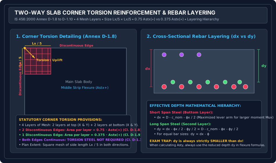
- Area of steel in each of the four layers: Where is the maximum positive flexural steel area per unit width at midspan in the short direction.
- Plan Extent: Provided over a square region of dimensions:
- One Edge Discontinuous, One Edge Continuous (Clause D-1.9):
- Area of steel in each of the four layers is halved:
- Extent: Square of side .
- Both Edges Continuous (Interior Slab Corners, Clause D-1.10):
- Torsion reinforcement is NOT required because the continuity of adjacent slab panels automatically suppresses corner torsional uplift.
5. Effective Depth Hierarchy ( vs )
Because steel runs in two perpendicular directions, bars in one direction must cross over bars in the other direction.
- Short Span Steel (): Placed in the outermost (bottom) layer to provide the maximum effective depth for resisting the larger short-span moment :
- Long Span Steel (): Placed in the second layer resting directly on top of the short-span steel: For equal bar diameters ():
[!WARNING] Because , the lever arm for the long span is smaller! When computing required reinforcement , you must use the reduced effective depth , not .
6. Engineering Diagrams & Detailing Anatomy
Diagram 1: Two-Way Slab Strip Division & Moment Formulation
The diagram below illustrates the subdivision into Middle Strip ( width) and Edge Strips ( width), Table 26 moment coefficients , and the scaling formulation.
       TWO-WAY SLAB STRIP DIVISION (PLAN VIEW)
 ┌─────────────────────────────────────────────────────────────┐
 │  Edge Strip (Lx/8)    Middle Strip (3/4 Lx)   Edge Strip    │
 │  ┌──────────┬─────────────────────────────┬──────────┐      │
 │  │ Edge     │      Edge Strip (Ly/8)      │ Edge     │      │
 │  ├──────────┼─────────────────────────────┼──────────┤      │
 │  │          │                             │          │      │
 │  │ Edge     │        MIDDLE STRIP         │ Edge     │      │
 │  │ Strip    │    (Max Mux = αx wu Lx²)    │ Strip    │      │
 │  │ (Lx/8)   │    (Max Muy = αy wu Lx²)    │ (Lx/8)   │      │
 │  │          │                             │          │      │
 │  ├──────────┼─────────────────────────────┼──────────┤      │
 │  │ Edge     │      Edge Strip (Ly/8)      │ Edge     │      │
 │  └──────────┴─────────────────────────────┴──────────┘      │
 └─────────────────────────────────────────────────────────────┘
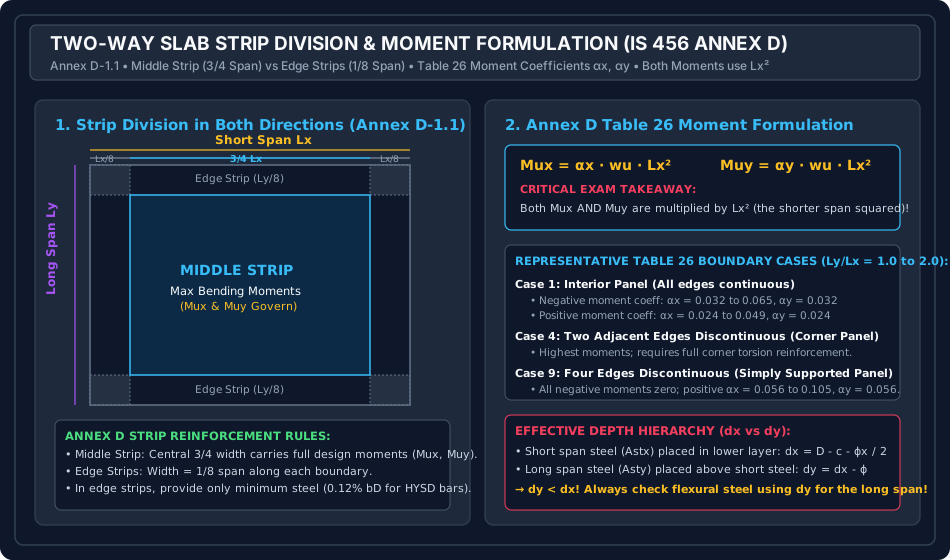
Diagram 2: Corner Torsion Reinforcement & Rebar Layering
The diagram below illustrates the corner mesh, 4 layers of torsion steel ( and ), and the cross-sectional effective depth hierarchy ( at bottom layer, in second layer).
       CORNER TORSION MESH & REBAR LAYERING
 ┌─────────────────────────────────────────────────────────────┐
 │  Corner Mesh: Lx/5 × Lx/5 (4 layers: 2 top + 2 bottom)      │
 │  ┌─────────┐                                                │
 │  │ 0.75Ast │                                                │
 │  └─────────┘                                                │
 │                                                             │
 │  Cross-Sectional Stacking:                                  │
 │  ────────────────────────────────────────── Concrete Top    │
 │   ●   ●   ●   ●   Long-span rebar (dy = dx - ϕ)             │
 │  ( ) ( ) ( ) ( )  Short-span rebar (dx = D - c - ϕ/2)       │
 │  ────────────────────────────────────────── Bottom Cover    │
 └─────────────────────────────────────────────────────────────┘
7. Step-by-Step Design Procedure for Two-Way Slabs
                     TWO-WAY SLAB DESIGN WORKFLOW
                                   │
 ┌─────────────────────────────────┴─────────────────────────────────┐
 │ 1. Verify Aspect Ratio: Ly / Lx ≤ 2.0 (Two-Way Action).           │
 │ 2. Assume Overall Depth D: D ≈ Span / 28 to Span / 35.            │
 │    Compute dx = D - c - ϕ/2 and dy = dx - ϕ.                      │
 │ 3. Determine Factored Load wu: wu = 1.5 · (Self-weight + Finish+LL│
 │ 4. Identify Boundary Condition: Select Case 1 to 9 (Table 26).    │
 │ 5. Compute Design Moments:                                        │
 │    Mux = αx · wu · Lx²;  Muy = αy · wu · Lx²                      │
 │ 6. Check Depth for Flexure: d ≥ √(Mux,max / (Q_lim · fck · 1000)) │
 │ 7. Compute Steel in Middle Strip:                                 │
 │    - Astx in short direction using dx                             │
 │    - Asty in long direction using dy                              │
 │    - Verify Ast ≥ Ast,min = 0.12% b·D                             │
 │ 8. Provide Edge Strip Steel: Minimum steel Ast,min in 1/8 strips. │
 │ 9. Design Corner Torsion Mesh:                                    │
 │    - 2 Discontinuous edges: 0.75 Astx(+) in 4 layers (Lx/5 size)  │
 │    - 1 Discontinuous edge: 0.375 Astx(+) in 4 layers (Lx/5 size)  │
 │ 10. Check Deflection & Shear:                                     │
 │     (Lx / dx)_actual ≤ 26 · kt;  τv = Vu / (b dx) ≤ k · τc.       │
 └───────────────────────────────────────────────────────────────────┘
8. Pre-Calculated Solved Numerical Examples
Example 1: Comprehensive Design of a Restrained Two-Way Slab (Annex D, Case 1)
Problem Statement:
Design an interior panel of a continuous two-way reinforced concrete floor slab supported on monolithic RC beams of width . Clear room dimensions are and .
Design data:
- Live load =
- Floor finish =
- Concrete grade = M20 ()
- Steel grade = Fe 415 ()
- Unit weight of concrete
Solution:
Step 1: Check Aspect Ratio:
Step 2: Effective Spans & Section Depth:
For monolithic beams, and .
To satisfy deflection control for a continuous panel ():
With clear cover and bars:
- Short direction effective depth:
- Long direction effective depth:
Step 3: Factored Loading:
- Self-weight:
- Finishes:
- Imposed load:
- Total service load:
- Factored load:
Step 4: Moment Coefficients from IS 456 Table 26 (Case 1: Interior Panel): For :
- Short span coefficients (interpolating between and ):
- Long span coefficients (independent of for Case 1):
Step 5: Factored Design Bending Moments:
Step 6: Flexural Depth Verification:
Step 7: Middle Strip Reinforcement Design: Minimum steel (Clause 26.5.2.1):
- Short Span Negative Steel (): Provide bars @ c/c ().
- Short Span Positive Steel (): Provide minimum steel: bars @ c/c ().
- Long Span Negative Steel (): Provide bars @ c/c ().
- Long Span Positive Steel (): Provide minimum steel: bars @ c/c ().
Step 8: Corner Torsion Check: Because this is an Interior Panel (Case 1) where all 4 edges are continuous:
Example 2: Corner Torsion Reinforcement Design per IS 456 Annex D
Problem Statement:
A corner panel of a two-way floor system has two adjacent discontinuous edges (Case 4). The shorter span is . The midspan positive flexural design requires .
Determine the size, number of layers, and required area of corner torsion reinforcement at:
- Corner A where both edges are discontinuous.
- Corner B where one edge is discontinuous and the other is continuous.
- Corner C where both edges are continuous.
Solution:
1. Dimension / Plan Extent of Torsion Reinforcement: Per Clause D-1.8, the torsion mesh must extend in both directions by:
2. Corner A (Both Edges Discontinuous — Exterior Building Corner):
- Per Clause D-1.8, reinforcement must be provided in four layers (2 top + 2 bottom).
- Area of reinforcement in each layer:
- Spacing using bars ():
3. Corner B (One Edge Discontinuous, One Continuous):
- Per Clause D-1.9, reinforcement in each of four layers: However, this must not be less than minimum reinforcement .
4. Corner C (Both Edges Continuous — Interior Corner):
- Per Clause D-1.10: Torsion reinforcement is NOT required ().
Example 3: Simply Supported Two-Way Slab using IS 456 Table 27
Problem Statement:
A room measuring clear dimensions is covered by a simply supported reinforced concrete slab with corners free to lift. The total factored working load is .
Using IS 456:2000 Table 27, calculate the design ultimate bending moments and .
Solution:
Step 1: Compute Aspect Ratio:
Step 2: Table 27 Moment Coefficients: For :
Step 3: Calculate Bending Moments:
(Note: Both and are scaled by per IS 456 Table 27).
9. Engineering Misconceptions & Site Detailing Pitfalls
┌────────────────────────────────────────┬────────────────────────────────────────┬────────────────────────────────────────┐
│ Site Error / Detailing Defect          │ Engineering Consequence                │ IS 456:2000 Mandatory Remedy         │
├────────────────────────────────────────┼────────────────────────────────────────┼────────────────────────────────────────┤
│ Multiplying long-span moment Muy by    │ Massive over-calculation of moment     │ Table 26 & 27 formulas strictly use    │
│ Ly² instead of Lx²                     │ (by a factor of (Ly/Lx)²); wasteful!   │ Lx² for both Mux and Muy!              │
├────────────────────────────────────────┼────────────────────────────────────────┼────────────────────────────────────────┤
│ Using effective depth dx when          │ Section becomes under-designed in the  │ Always use reduced depth dy = dx - ϕ   │
│ computing long-span steel Asty         │ long direction; risk of cracking.      │ for long-span flexural calculations.   │
├────────────────────────────────────────┼────────────────────────────────────────┼────────────────────────────────────────┤
│ Omitting corner torsion mesh at        │ Diagonal tension cracks split the top  │ Provide 4 layers of mesh (0.75 Astx+)  │
│ exterior discontinuous corners         │ and bottom surfaces of slab corners!   │ extending Lx/5 in both directions.     │
├────────────────────────────────────────┼────────────────────────────────────────┼────────────────────────────────────────┤
│ Providing corner torsion mesh at       │ Waste of steel and unnecessary         │ Torsion steel is strictly EXEMPT at    │
│ interior continuous corners            │ construction cost.                     │ continuous corners (Clause D-1.10).    │
└────────────────────────────────────────┴────────────────────────────────────────┴────────────────────────────────────────┘
10. Comparative Summary: IS 456 Slab Design Methods
| Parameter | Simply Supported (Table 27) | Restrained Slabs (Annex D Table 26) |
|---|---|---|
| Corner Boundary | Corners free to lift | Corners held down / cast monolithic with beams |
| Torsion Action | Corners lift; no torsion reinforcement provided | Restrained torsion induces corner twisting moments |
| Corner Mesh | None | Mandatory at discontinuous edges ( size) |
| Middle Strip Width | Entire slab width | Central width () |
| Edge Strip Width | None | Perimeter width () |
| Edge Strip Steel | Full moment steel throughout | Minimum steel () in edge strips |
| Support Moments | Zero (simply supported) | Negative hogging moments resisted over supports |
11. Competitive Exam Traps & High-Yield Takeaways
[!CAUTION] GATE / ESE High-Yield Trap Checklist:
- Table 26 & 27 Formula Multiplier: Both and use !
- Middle Strip vs Edge Strip Proportions: Middle strip (). Edge strips () on each side.
- Corner Torsion Size: Extent is (one-fifth of the shorter span), NOT and NOT .
- Corner Torsion Layers: Always 4 layers of mesh (2 at top face, 2 at bottom face).
- Corner Torsion Steel Area:
- 2 edges discontinuous: .
- 1 edge discontinuous: .
- Both edges continuous: ZERO (Not required).
- Effective Depth Hierarchy: is greater than . Never use for long-span steel!
12. Practice Questions & Exercises
Question 1 (GATE CE)
A two-way reinforced concrete slab of size is simply supported on all four edges. The corners are free to lift. Using IS 456 Table 27 coefficients () under a factored load of , the design bending moments in the short and long directions ( and ) are respectively:
- (A) and
- (B) and
- (C) and
- (D) and
Answer: (A)
Explanation:
.
.
.
(Notice that uses , NOT !).
Question 2 (UPSC ESE)
Per IS 456:2000 Annex D, at a corner where one edge of a slab is continuous and the other edge is discontinuous, the area of torsion reinforcement provided in each of the four layers over a square of side shall be:
- (A) times the maximum positive midspan flexural reinforcement
- (B) times the maximum positive midspan flexural reinforcement
- (C) times the maximum positive midspan flexural reinforcement
- (D) times the maximum positive midspan flexural reinforcement
Answer: (C)
Explanation:
Per Clause D-1.9, when one edge is discontinuous and one continuous, the required area per layer is half of , which equals .
Question 3 (SSC JE / State AE)
In a two-way restrained slab, the width of the middle strip in either direction is:
- (A) of the slab span
- (B) of the slab span
- (C) of the slab span
- (D) of the slab span
Answer: (C)
Explanation:
Per IS 456 Annex D-1.1, the middle strip occupies the central three-quarters () of the span, while the edge strips occupy the remaining one-eighth () along each edge.