Isolated Footings (Soil Pressure Distribution, Flexure & Central Band Reinforcement)
In this chapter (3 topics)
On this page
- 1. Introduction to Shallow Foundations and Isolated Footings
- 2. Soil Pressure Mechanics: Working State vs Limit State
- 2.1 Sizing the Plan Dimensions L × B (Working Stress State)
- 2.2 Factored Net Upward Soil Reaction qu (Limit State Design)
- 3. Eccentric Footing Loading: Kern Limits and Soil Separation
- 3.1 Load within the Kern (e ≤ fracL6)
- 3.2 Load outside the Kern (e > fracL6)
- 4. Critical Section for Bending Moment (IS 456 Clause 34.2.3.1)
- 5. Mathematical Derivation of Flexural Bending Moments
- 5.1 Moment in the Long Direction (Mux about Section Y-Y)
- 5.2 Moment in the Short Direction (Muy about Section X-X)
- 5.3 Limiting Depth for Flexure
- 6. Central Band Reinforcement Distribution in Rectangular Footings
- 6.1 Central Band Reinforcement Ratio
- 6.2 Outer Bands Reinforcement
- 7. Bearing Stress at Column-Footing Interface & Force Transfer
- 7.1 Permissible Bearing Stress
- 7.2 Transfer of Excessive Force by Starter Bars (Dowels)
- 8. Detailed Engineering Diagrams & Visual Walkthrough
- Figure 1: Isolated Footing Soil Pressure & Critical Sections
- Figure 2: Central Band Distribution in Rectangular Footings & Detailing Rules
- 9. Pre-Calculated Solved Numerical Examples
- Problem 1: Complete Flexural Design of a Square Isolated Footing
- Problem 2: Rectangular Footing with Central Band Reinforcement Distribution
- Problem 3: Soil Pressure Analysis and Flexure under Eccentric Column Load
- 10. Comprehensive Comparison Table: Footing Types & Soil Reaction Profiles
- 11. Practical Detailing and Common Field Pitfalls
- 12. Competitive Examination Traps & Quick Formula Sheet
- Common Exam Traps
- Master Formula Sheet
- 13. Practice Problems
- Problem 1 (GATE CE Format - NAT)
- Problem 2 (UPSC ESE Format - Multiple Choice)
- Problem 3 (State AE / SSC JE Format)
1. Introduction to Shallow Foundations and Isolated Footings
Foundations are the substructure structural elements that safely transmit vertical superstructural column loads, lateral wind/earthquake shears, and overturning moments into the supporting geotechnical stratum.
- Shallow Foundations: Defined per Terzaghi as foundations where the embedment depth is less than or equal to the lateral width ().
- Isolated (Spread or Pad) Footings: The most common, cost-effective type of shallow foundation, provided beneath individual columns. They can be prismatic (flat pad of uniform depth), stepped, or sloped (trapezoidal in elevation with a flat horizontal edge).
   Prismatic (Pad) Footing:        Sloped (Trapezoidal) Footing:
           Column                         Column
            │  │                           │  │
       ┌────┴──┴────┐                 ┌────┴──┴────┐
       │            │                / │          │ \
       └────────────┘               └──┴──────────┴──┘  ◄── D_edge ≥ 150 mm
Under gravity column loading , the footing deflects in two-way dishing curvature (cantilever action), with the footing slab bending upward around the column perimeter due to the distributed upward reactive soil pressure. Consequently:
- The bottom face is subjected to biaxial tension, requiring a two-way orthogonal mesh of tensile reinforcement.
- The top face is in compression.
- The critical design requirements per IS 456:2000 (Clause 34) encompass plan sizing for allowable bearing pressure, critical sections for bending moment, one-way beam shear, two-way punching shear, and compressive force transfer across the column-footing interface.
2. Soil Pressure Mechanics: Working State vs Limit State
A fundamental source of error in foundation design is confusing serviceability soil bearing capacity with factored limit state upward pressure:
2.1 Sizing the Plan Dimensions (Working Stress State)
The plan area of the footing is determined based on the Safe Bearing Capacity ( or ) of the soil under unfactored service loads ():
- Self-Weight Allowance: The self-weight of the footing slab and the soil backfill surcharge above it are estimated as an additional of the column service load:
- Required Plan Area:
- For a square footing (): .
- For a rectangular footing (): Dimensions are selected such that the cantilever overhangs in both directions are approximately equal to balance bending moments:
2.2 Factored Net Upward Soil Reaction (Limit State Design)
Once the plan dimensions are finalized, the structural thickness and flexural reinforcement of the concrete footing slab are designed using the factored ultimate load:
[!IMPORTANT] Why is the self-weight of the footing excluded when computing ? The self-weight of the concrete footing and the soil backfill act as uniform downward gravity loads directly over the entire area . These downward forces are directly and identically balanced by a corresponding uniform upward soil reaction. They produce pure vertical equilibrium without causing any bending moment, transverse shear, or punching shear in the footing slab! Therefore, only the net upward soil reaction is considered for flexural and shear design.
3. Eccentric Footing Loading: Kern Limits and Soil Separation
When an isolated column transmits a factored axial load accompanied by an overturning moment (due to wind, earthquake, or eccentric column placement), the eccentricity is:
The resulting soil pressure distribution depends strictly on whether the load falls inside or outside the kern (middle-third) of the footing:
Case A: Concentric (e = 0)     Case B: Within Kern (e ≤ L/6)     Case C: Beyond Kern (e > L/6)
       Uniform                        Trapezoidal                      Triangular (Separation)
    ┌───────────┐                    ┌───────────┐                     ┌───────────┐
    │           │                    │\          │                     │\          │
    │           │                    │ \         │                     │ \         │
    │           │                    │  \        │                     │  \        │
    └───────────┘                    └───┴───────┘                     └───┴───────┘
       q = P/A                      q_max     q_min                   q_max   (Zero over gap)
3.1 Load within the Kern ()
No separation occurs; compressive contact is maintained across the entire contact length . The pressure varies linearly as a trapezoid:
Where is the section modulus of the footing plan area about the bending axis.
- When : , producing a triangular pressure distribution with zero tension at the heel.
- Under service loads, (or when wind/seismic loads are included).
3.2 Load outside the Kern ()
Because soil has zero tensile strength, separation (lift-off) occurs at the heel. The effective bearing length reduces to , and equilibrium of vertical forces yields a triangular compression stress block:
4. Critical Section for Bending Moment (IS 456 Clause 34.2.3.1)
Under the upward pressure , each cantilever projection of the footing slab bends upward like an inverted cantilever beam supported at the column base.
According to IS 456:2000 (Clause 34.2.3.1), the critical section for checking the maximum factored bending moment is taken at:
| Type of Column / Superstructure | Exact Location of Critical Section for Flexure | Physical Rationale |
|---|---|---|
| Concrete Column or Pedestal | At the face of the column, pedestal, or wall | Concrete column is rigid monolithic concrete; cantilever flexure begins at the perimeter interface. |
| Masonry Wall | Halfway between the centerline and the edge of the wall | Masonry has lower shear and flexural rigidity; partial stress dispersal occurs into the outer half of the masonry wall. |
| Steel Column with Gusseted Base | Halfway between the face of the column and the edge of the gusseted base plate | Stiff steel gusset plate and base plate distribute the column thrust across the plate width before entering concrete. |
Concrete Column:                  Masonry Wall:                     Gusseted Steel Base:
    │ Col │                          │ Wall │                            │Col│
────┼─────┼────                    ──┼──┼──┼───                    ──────┼─┼─┼─┼─────
    ▲     ▲                          ▲  ▲  ▲                             ▲ ▲ ▲ ▲
    Face of Column                   Halfway between                     Halfway between col face
    (Critical Section)               center & edge                       & gusset plate edge
5. Mathematical Derivation of Flexural Bending Moments
Consider an isolated rectangular footing of dimensions supporting a column of cross-section under concentric ultimate load :
- Factored uniform upward soil reaction:
5.1 Moment in the Long Direction ( about Section )
The cantilever overhang projecting beyond the column face along the length is:
The total upward soil force acting on this cantilever area is:
Because the pressure is uniform, the resultant force acts at the centroid of the cantilever projection, at distance from the column face:
Substituting :
5.2 Moment in the Short Direction ( about Section )
Similarly, the cantilever overhang projecting beyond the column face along the width is:
The total bending moment at the column face across width is:
For a square footing () supporting a square column (), , and:
5.3 Limiting Depth for Flexure
The minimum effective depth required to resist the ultimate bending moment without compression reinforcement is:
Where :
- For Fe 415:
- For Fe 500:
[!NOTE] In practical footing design, the depth required for flexure is relatively small (). The design thickness of an isolated footing is almost invariably governed by one-way shear or two-way punching shear, which requires substantially greater depth ().
6. Central Band Reinforcement Distribution in Rectangular Footings
In a square footing (), bending moments and dishing curvatures are identical in both directions. Therefore, tensile reinforcement is distributed uniformly across the entire width in both orthogonal directions.
However, in a rectangular footing (, with aspect ratio ):
- In the long direction (span ): The bending moment is resisted across the entire width . Hence, the total steel is distributed uniformly across the entire width .
- In the short direction (span ): The bending moment is concentrated heavily in the region directly beneath and adjacent to the column shaft. Distributing short-direction steel uniformly would leave the zone under the column dangerously under-reinforced, while over-reinforcing the remote outer edges.
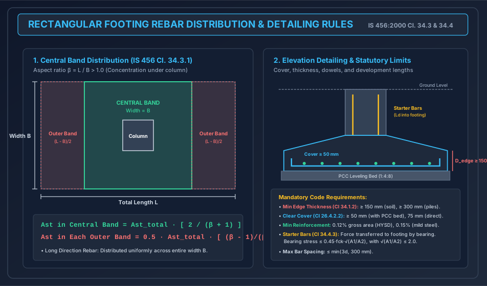
To resolve this, IS 456:2000 (Clause 34.3.1) specifies the Central Band Rule:
                       ◄─────────────── Length L ───────────────►
                      ┌──────────────┬──────────────────┬──────────────┐
                      │              │                  │              │
                      │  Outer Band  │   CENTRAL BAND   │  Outer Band  │
                      │  (L - B)/2   │    (Width B)     │  (L - B)/2   │
              Width B │              │    ┌────────┐    │              │
                      │              │    │ Column │    │              │
                      │              │    └────────┘    │              │
                      │              │                  │              │
                      └──────────────┴──────────────────┴──────────────┘
6.1 Central Band Reinforcement Ratio
In the short direction, a central band of width equal to the lateral width of the footing is marked symmetrically about the column centerline:
Where:
- is the aspect ratio of the footing ().
6.2 Outer Bands Reinforcement
The remaining reinforcement in the short direction is distributed uniformly across the two outer end bands, divided equally:
[!TIP] Notice the boundary checks for the Central Band formula:
- For a square footing (): ( in central band of width , meaning completely uniform distribution).
- For : in the central band, with in each outer band.
7. Bearing Stress at Column-Footing Interface & Force Transfer
At the interface between the column shaft and the footing slab, the factored axial compressive force must be safely transferred from the column concrete into the footing concrete.
According to IS 456:2000 (Clause 34.4):
7.1 Permissible Bearing Stress
The permissible compressive bearing stress on concrete at the interface is given by:
Where:
- = loaded bearing area at the base of the column .
- = maximum supporting area of the footing that is geometrically similar to and concentric with the loaded area , formed by projecting slopes of downwards to the footing base.
- Ratio (statutory code upper bound).
7.2 Transfer of Excessive Force by Starter Bars (Dowels)
- If Actual Bearing Stress :
- Concrete in direct bearing is fully capable of transferring the entire axial thrust without distress.
- If Actual Bearing Stress exceeds Permissible Bearing Stress:
- The excess compressive force must be transferred into the footing through extended longitudinal column bars or separate starter dowel bars:
- Statutory Minimum Dowel Area (Clause 34.4.3): Even if concrete bearing is completely adequate, the column-footing junction must provide a minimum reinforcement of: With a minimum of bars, extending a development length into both the column and the footing.
8. Detailed Engineering Diagrams & Visual Walkthrough
Figure 1: Isolated Footing Soil Pressure & Critical Sections
The diagram below details the elevation view of an isolated footing under upward factored soil reaction , highlighting the critical section for bending moment at the column face, and the plan view showing cantilever projections and .
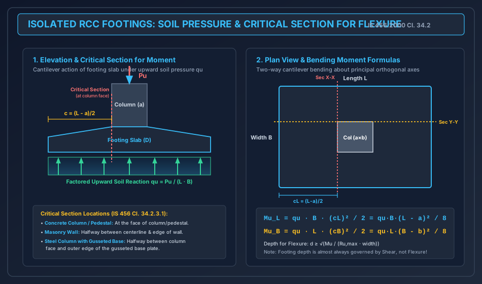
Figure 2: Central Band Distribution in Rectangular Footings & Detailing Rules
The diagram below illustrates the rectangular footing aspect ratio , the division into Central Band () and Outer Bands, along with essential detailing parameters (minimum edge thickness , clear cover , and starter dowel bars).
9. Pre-Calculated Solved Numerical Examples
Problem 1: Complete Flexural Design of a Square Isolated Footing
Statement: A square reinforced concrete column of size carries a service axial load . The safe bearing capacity of the soil is . Using M25 grade concrete () and Fe 415 steel ():
- Determine the required plan dimensions .
- Compute the factored upward net soil pressure .
- Determine the maximum factored bending moment at the critical section.
- Calculate the required flexural tensile reinforcement and provide a practical detailing arrangement assuming an overall thickness and effective depth .
Solution:
Step 1: Plan Sizing of Footing
- Column service load
- Self-weight of footing and soil overburden estimated at :
- Required plan area:
- Side of square footing:
- Adopt a square footing of side :
- Check actual service pressure:
Step 2: Factored Upward Soil Pressure
Factored column load:
Net factored upward soil reaction (excluding self-weight):
Step 3: Critical Section for Flexure and Maximum Bending Moment
Critical section is at the face of the column. Cantilever projection:
Maximum factored bending moment at column face:
Step 4: Check Depth Required for Flexure
For Fe 415, :
The provided effective depth (Adequate for flexure; governed by shear).
Step 5: Area of Tensile Reinforcement
- Check minimum steel ( of gross area): Since , provide .
Step 6: Reinforcement Detailing
Using bars ():
Provided steel:
Center-to-center spacing (with side covers):
Check maximum spacing limit:
Since , spacing is OK.
Arrangement: Provide bars at c/c uniformly distributed in both orthogonal directions as a bottom reinforcement mesh.
Problem 2: Rectangular Footing with Central Band Reinforcement Distribution
Statement: A rectangular isolated footing has plan dimensions and , supporting a column of size ( along , along ). The factored upward soil reaction is . Effective depth , concrete M25, steel Fe 415.
- Calculate the factored design moments in the long and short directions ( and ).
- Determine the required tensile reinforcement areas and .
- Apportion the short-direction reinforcement between the Central Band and Outer Bands per IS 456 Clause 34.3.1.
Solution:
Step 1: Bending Moment in Long Direction ()
- Length , column dimension
- Cantilever projection in long direction:
- Factored bending moment at column face across width :
Step 2: Bending Moment in Short Direction ()
- Width , column dimension
- Cantilever projection in short direction:
- Factored bending moment at column face across length :
Step 3: Steel Requirements in Both Directions
-
Long Direction (, width ):
This reinforcement is distributed uniformly across the entire width .
-
Short Direction (, length ):
Step 4: Apportionment of Short-Direction Steel (Central Band Rule)
- Aspect ratio of footing:
- Central Band fraction:
- Steel in Central Band (Width centered on column):
- Remaining steel for outer bands:
- Steel in Each Outer Band (Width ):
Conclusion: In the short direction, provide in the central band, and in each of the two outer edge bands.
Problem 3: Soil Pressure Analysis and Flexure under Eccentric Column Load
Statement: A rectangular footing supports a column . The column carries a service axial load and an overturning moment parallel to the side. The self-weight of the footing is estimated as of .
- Check soil pressures under service loads to verify if tension separation occurs.
- Calculate factored soil pressures and .
- Calculate the factored bending moment at the face of the column on the maximum pressure side.
Solution:
Step 1: Service Load Eccentricity Check
-
Total vertical service load:
-
Service moment:
-
Eccentricity:
-
Kern limit for rectangular section ():
Since , the load lies well inside the kern No tension lift-off occurs.
-
Service soil pressures ():
Step 2: Factored Soil Pressures (Net, Excluding Footing Weight)
Factored loads:
Step 3: Bending Moment at Column Face (Maximum Pressure Side)
Column face is at distance from the column centerline. Cantilever length:
Upward pressure at the column face by linear interpolation:
The upward pressure on the cantilever projection of length varies trapezoidally from (at face) to (at edge).
- Average pressure:
- Total upward force on cantilever:
- Centroid of trapezoid from column face:
- Factored bending moment at column face:
10. Comprehensive Comparison Table: Footing Types & Soil Reaction Profiles
| Parameter / Feature | Square Footing () | Rectangular Footing () | Concentric Footing () | Eccentric Footing () |
|---|---|---|---|---|
| Soil Reaction Profile | Uniform across entire slab | Uniform across entire slab | Uniform rectangular () | Linear trapezoidal () |
| Cantilever Projections | Symmetrical on opposite sides | Unequal moment on opposite faces | ||
| Flexural Rebar Layout | Uniform in both directions | Uniform in long; Central Band in short | Identical rebar on opposite sides | Heavier rebar on side |
| Central Band Rule | Not applicable () | Mandatory: in band | Not applicable | Applied to governing short direction |
| Design Moment Formula | Parabolic variation from face | Trapezoidal moment integration | ||
| Preferred Application | Isolated square columns | Boundary restrictions, rectangular columns | Central interior columns | Corner / exterior columns, wind/seismic |
11. Practical Detailing and Common Field Pitfalls
- Self-Weight Trap in Flexure:
- Adding footing self-weight when calculating factored upward soil reaction for bending moment or shear design is a severe design error. It falsely overestimates moments by .
- Correct Rule: Use self-weight ONLY for plan sizing with . Exclude self-weight when computing for thickness and steel.
- Minimum Edge Thickness Violation:
- In sloped or stepped footings, contractors frequently taper the footing down to a knife-edge of at the perimeter.
- Statutory Code Limit (IS 456 Clause 34.1.2): Thickness at the edge shall never be less than for footings on soil (or for footings on piles).
- Omitting the Central Band in Rectangular Footings:
- Distributing short-direction reinforcement uniformly across a rectangular footing violates Clause 34.3.1. Under high column loads, wide longitudinal flexural cracks develop directly beneath the column shaft.
- Concrete Cover against Soil:
- Never provide a nominal cover of in footings.
- Per Clause 26.4.2.2, minimum cover is when cast over a lean concrete leveling bed (PCC 1:4:8), and if cast directly against excavated earth.
12. Competitive Examination Traps & Quick Formula Sheet
Common Exam Traps
- Critical Section for Flexure across Support Types:
- Concrete column At column face.
- Masonry wall Halfway between centerline and wall edge.
- Gusseted steel base Halfway between column face and gusset base edge.
- Central Band Fraction Formula:
- Central band fraction is , NOT or .
- Each outer band gets .
- Minimum Dowel Reinforcement:
- Minimum area of starter bars transferring load from column to footing is of column area (), with at least bars.
- Kern Limit for Soil Tension:
- Tension begins when eccentricity (the kern boundary).
- If , and .
Master Formula Sheet
13. Practice Problems
Problem 1 (GATE CE Format - NAT)
A rectangular isolated footing of size is provided for a column. The total tensile reinforcement required in the short direction ( span) is . As per IS 456:2000, the amount of tensile reinforcement to be placed in the central band of width is ________ . (Calculation: . Fraction in central band . Steel in central band . Answer: )
Problem 2 (UPSC ESE Format - Multiple Choice)
As per IS 456:2000, the critical section for the maximum bending moment in the design of an isolated footing supporting a masonry wall is located:
- (A) At the face of the wall
- (B) At the centerline of the wall
- (C) Halfway between the centerline and the edge of the wall
- (D) At a distance equal to effective depth from the face of the wall (Answer: (C) Halfway between the centerline and the edge of the wall)
Problem 3 (State AE / SSC JE Format)
What is the minimum thickness of an isolated reinforced concrete footing at its edge, when supported on soil, as prescribed by IS 456:2000?
- (A)
- (B)
- (C)
- (D) (Answer: (B) per Clause 34.1.2. For pile foundations, it is .)