Limit State of Deflection in Reinforced Concrete
In this chapter (3 topics)
On this page
- 1. Introduction & Executive Summary
- 2. IS 456 Permissible Deflection Limits (Clause 23.2)
- 3. Empirical Control: Span-to-Effective-Depth (L/d) Ratios
- 3.1 Basic (L/d)0 Ratios for Spans up to 10 m
- 3.2 Spans Exceeding 10 m Scaling Rule
- 4. Formulation of Modification Factors (kt, kc, kf)
- 4.1 Modification Factor for Tension Reinforcement (kt)
- 4.2 Modification Factor for Compression Reinforcement (kc)
- 4.3 Reduction Factor for Flanged Beams (kf)
- 5. Rigorous Calculation Method (IS 456 Annex C)
- 5.1 Short-Term (Instantaneous) Deflection (δi)
- 5.2 Long-Term Deflection Components
- 6. High-Precision Engineering Diagrams
- 6.1 Deflection Control: Span-to-Depth Ratios & Modification Factors
- 6.2 Long-Term Deflection Mechanics: Branson's I_eff, Creep & Shrinkage Warping
- 7. Pre-Calculated Solved Numerical Examples
- Problem 1: Empirical L/d Verification for a Flanged T-Beam (GATE CE / UPSC ESE)
- Problem 2: Deflection Control for Long-Span Continuous Beam (L > 10 m) (UPSC ESE / State AE)
- Problem 3: Annex C Rigorous Deflection Calculation (GATE CE)
- 8. Comparative Analysis: Serviceability Parameters
- 9. Practical Design & Construction Guidelines
- 10. Common Misconceptions & Exam Traps
- 11. Practice Questions for Self-Assessment
1. Introduction & Executive Summary
While the Limit State of Collapse ensures that a reinforced concrete (RC) structure possesses adequate strength to prevent catastrophic structural failure under extreme factored loads, the Limit State of Serviceability ensures that the structure behaves satisfactorily under normal day-to-day working (service) loads throughout its intended design life.
A structure that is fully safe against ultimate collapse may nonetheless prove completely unserviceable if it undergoes excessive deflections. Excessive deflection leads to severe engineering hazards:
- Structural Damage to Non-Structural Elements: Cracking of brittle partition walls (brickwork, drywall), shattering of glass façades, and damage to floor tiling and plastering.
- Operational Malfunctions: Jamming of doors, windows, and elevator guides; misalignment of sensitive machinery and overhead crane rails.
- Ponding of Water: On flat roofs, excessive sag traps rainwater, increasing dead weight and precipitating progressive ponding instability.
- Psychological Discomfort: Visible structural sag induces fear and alarm among building occupants and severely impairs building aesthetics.
To satisfy serviceability without requiring complex non-linear finite element computations for every routine beam, IS 456:2000 provides two distinct design paths:
- Empirical Deemed-to-Satisfy Method: Control of Span-to-Effective-Depth () ratios using basic ratios modified for tension steel (), compression steel (), and flange geometry ().
- Theoretical Calculation Method (Annex C): Explicit calculation of short-term deflection using Branson's Effective Moment of Inertia () and long-term deflection incorporating creep and shrinkage warping.
2. IS 456 Permissible Deflection Limits (Clause 23.2)
To satisfy serviceability, the vertical deflection of a flexural member must not exceed two statutory criteria under service loads:
                            IS 456 DEFLECTION LIMITS
                                       │
            ┌──────────────────────────┴──────────────────────────┐
            ▼                                                     ▼
    TOTAL FINAL DEFLECTION                              INCREMENTAL DEFLECTION
 (From As-Cast Level of Supports)                    (After Partitions & Finishes)
 ┌──────────────────────────────┐                   ┌──────────────────────────────┐
 │ • Includes dead load, live   │                   │ • Occurring AFTER finishes,  │
 │   load, temperature, creep,  │                   │   plaster, and partitions    │
 │   and shrinkage              │                   │ • Prevents cracking of walls │
 │ • Limits visible sag & pond  │                   │ • Limits window/door jamming │
 │                              │                   │                              │
 │   δ_final ≤ Span / 250       │                   │   δ ≤ min(Span / 350, 20 mm) │
 └──────────────────────────────┘                   └──────────────────────────────┘
-
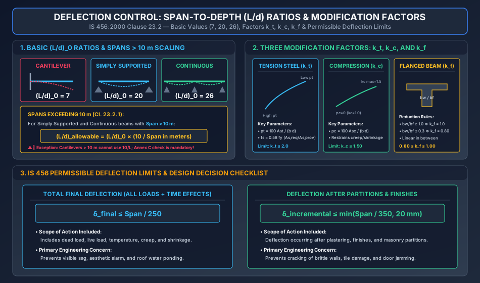
Total Final Deflection Limit (Clause 23.2.a):
The final deflection due to all loads (including the long-term effects of temperature, creep, and shrinkage), measured from the as-cast level of the supports of floors, roofs, and all other horizontal members, should not normally exceed: -
Incremental Deflection Limit (Clause 23.2.b):
The deflection including the effects of temperature, creep, and shrinkage occurring after the erection of partitions and the application of finishes should not normally exceed:Crucial Detail for Exams: The absolute upper ceiling is mandatory; for spans exceeding (), the deflection must never exceed regardless of span length!
3. Empirical Control: Span-to-Effective-Depth () Ratios
Per IS 456 Clause 23.2.1, for beams and slabs with spans up to , deflection criteria are deemed satisfied if the actual span-to-effective-depth ratio does not exceed the permissible value:
Where:
- = Basic span-to-effective-depth ratio.
- = Modification factor for longitudinal tension reinforcement (Figure 4).
- = Modification factor for longitudinal compression reinforcement (Figure 5).
- = Reduction factor for flanged beams (Figure 6).
3.1 Basic Ratios for Spans up to
| Support Condition | Basic Ratio | Physical Rationale |
|---|---|---|
| Cantilever | 7 | Fixed at one end, free at other; maximum deflection occurs at tip (). Highest curvature. |
| Simply Supported | 20 | Standard benchmark; positive midspan curvature under uniform load (). |
| Continuous / Fixed | 26 | Restrained ends induce negative hogging moments that reduce midspan sagging deflection by up to . |
3.2 Spans Exceeding Scaling Rule
For spans greater than , deflections increase drastically because deflection is proportional to the fourth power of span (), while strength requires depth proportional only to .
Per IS 456 Clause 23.2.1:
- For Simply Supported and Continuous beams having spans exceeding , the basic values are multiplied by:
- Absolute Code Exception (Frequent Exam Trap):
"For cantilevers which exceed in span, the basic value shall NOT be scaled by . Cantilevers exceeding must be designed based on rigorous calculation of deflections per Annex C."
4. Formulation of Modification Factors ()
                       EMPIRICAL MODIFICATION FACTORS
                                       │
            ┌──────────────────────────┼──────────────────────────┐
            ▼                          ▼                          ▼
    TENSION STEEL (k_t)        COMPRESSION STEEL (k_c)     FLANGED BEAMS (k_f)
 ┌───────────────────────┐    ┌───────────────────────┐   ┌───────────────────────┐
 │ • Decreases as pt ↑   │    │ • Increases as pc ↑   │   │ • Decreases as web    │
 │ • Decreases as fs ↑   │    │ • Restrains creep and │   │   ratio bw/bf ↓       │
 │ • Upper bound: 2.0    │    │   shrinkage warping   │   │ • Bound: 0.80 to 1.00 │
 │                       │    │ • Upper bound: 1.50   │   │                       │
 └───────────────────────┘    └───────────────────────┘   └───────────────────────┘
4.1 Modification Factor for Tension Reinforcement ()
The modification factor accounts for the extent of flexural cracking. As the percentage of tensile steel increases, the neutral axis shifts deeper, increasing the depth of cracking and lowering the effective cracked moment of inertia , which increases deflections. Hence, decreases as increases.
The factor depends on:
- Percentage of tension steel: (computed on web width for flanged beams).
- Service stress in steel (): (Note: is the inverse of the global safety factor under service conditions).
The empirical formula representing IS 456 Figure 4 is:
4.2 Modification Factor for Compression Reinforcement ()
Concrete under sustained compression creeps and shrinks over time. If a beam contains reinforcement on the compression face (), the compression steel does not creep. As the surrounding concrete creeps, compressive stress sheds from the concrete into the rigid steel bars, arresting progressive creep curvature.
Furthermore, compression steel balances drying shrinkage shortening across the depth, eliminating downward shrinkage warping!
The factor depends on the percentage of compression steel :
| Compression Steel | 0.0% | 0.25% | 0.50% | 0.75% | 1.00% | 1.50% | |
|---|---|---|---|---|---|---|---|
| Factor | 1.00 | 1.08 | 1.16 | 1.23 | 1.30 | 1.40 | 1.50 (Max) |
Engineering Significance: Providing compression steel can increase the allowable span-to-depth ratio by up to , making doubly reinforced beams exceptionally slender and deflection-resistant.
4.3 Reduction Factor for Flanged Beams ()
In flanged beams (T-beams and L-beams), a large concentration of concrete area exists in the compression flange, while the web below is cracked. This asymmetry shifts the neutral axis upward, reducing the cracked moment of inertia compared to a solid rectangular beam of width .
Per IS 456 Clause 23.2.1 and Figure 6, depends on the ratio of web width to flange width ():
- For (Rectangular Beam): .
- For : .
- For : Linear interpolation applies:
5. Rigorous Calculation Method (IS 456 Annex C)
For non-standard spans, irregular loading, or when empirical checks fail, explicit calculation of deflections must be performed per Annex C.
5.1 Short-Term (Instantaneous) Deflection ()
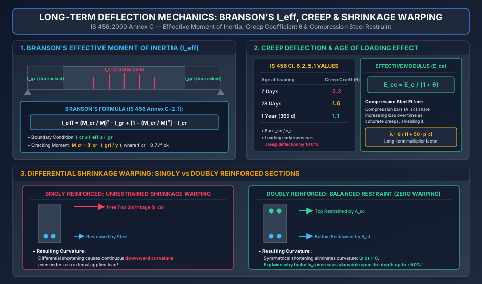
Short-term deflection under service loads is calculated using standard elastic structural analysis formulas (e.g. for a simply supported beam under UDL), but using Branson's Effective Moment of Inertia ():
Subject to the physical boundary conditions:
Where:
- = Cracking moment of the concrete section:
- = Maximum service load bending moment at the critical design section.
- = Gross uncracked moment of inertia of the concrete section (ignoring steel).
- = Distance from the centroidal axis of the uncracked section to the extreme tension fiber.
- = Cracked moment of inertia of the transformed section: Where is the short-term modular ratio, and is the depth of the cracked neutral axis found by taking moments of area about the neutral axis:
                       TRANSITION OF MOMENT OF INERTIA
      M ≤ M_cr                      M > M_cr                        M >> M_cr
  ┌───────────────┐          ┌───────────────────────┐          ┌───────────────┐
  │   UNCRACKED   │          │   PARTIALLY CRACKED   │          │ FULLY CRACKED │
  │   I_eff = I_gr│   ───►   │ Branson Transition    │   ───►   │  I_eff ≈ I_cr │
  │ Elastic Homog │          │ I_cr < I_eff < I_gr   │          │ Only Steel &  │
  │  Concrete     │          │ Tension Stiffening    │          │ Concrete Head │
  └───────────────┘          └───────────────────────┘          └───────────────┘
5.2 Long-Term Deflection Components
Total long-term deflection comprises three additive components:
1. Creep Deflection ():
Creep is the progressive time-dependent deformation of concrete under sustained compressive stress.
- Creep Coefficient per IS 456 Clause 6.2.5.1:
- Age at loading
- Age at loading
- Age at loading
- Effective Modulus of Elasticity ():
- Long-term deflection multiplier () on sustained instantaneous deflection:
2. Shrinkage Deflection ():
Drying shrinkage causes concrete to shorten. In a singly reinforced beam, the presence of longitudinal steel at the bottom restrains concrete shrinkage, while the unreinforced top concrete shrinks freely. This differential shortening induces downward shrinkage curvature ():
Where:
- = Ultimate drying shrinkage strain of concrete ( per IS 456 Clause 6.2.4.1).
- (for , ).
- Shrinkage deflection at midspan: (Where for simply supported beams, for cantilevers, and for continuous beams).
6. High-Precision Engineering Diagrams
6.1 Deflection Control: Span-to-Depth Ratios & Modification Factors
The diagram below details the basic ratios (7, 20, 26), the scaling rule, the mechanics and formulas of , and the two IS 456 serviceability limits ( and ).
6.2 Long-Term Deflection Mechanics: Branson's I_eff, Creep & Shrinkage Warping
The diagram below details Branson's transition along a flexural span, the age-of-loading creep table and effective modulus , and the differential shrinkage mechanics comparing singly vs doubly reinforced beams.
7. Pre-Calculated Solved Numerical Examples
Problem 1: Empirical Verification for a Flanged T-Beam (GATE CE / UPSC ESE)
Statement:
A simply supported T-beam has an effective span . The cross-sectional dimensions are:
- Web width
- Effective flange width
- Overall depth
- Effective depth
The beam is reinforced with:
- Tension steel: 4 bars of diameter (). Design requires .
- Compression steel: 2 bars of diameter ().
- Steel grade Fe 415 () and concrete grade M25.
Check whether the beam satisfies the IS 456:2000 deflection control criteria.
Step 1: Basic Span-to-Depth Ratio
For a simply supported beam with span :
Step 2: Modification Factor for Tension Reinforcement ()
Percentage tension reinforcement (computed based on web width ):
Service stress in tension steel ():
Using the empirical formula for :
Step 3: Modification Factor for Compression Reinforcement ()
Percentage compression reinforcement:
Step 4: Reduction Factor for Flanged Beam ()
Ratio of web width to flange width:
Since , per IS 456 Figure 6:
Step 5: Permissible Span-to-Depth Ratio
Step 6: Comparison & Verification
- Actual provided span-to-depth ratio:
- Minimum required effective depth to satisfy deflection:
Remedial Engineering Recommendations:
- Increase effective depth from to at least ( or ).
- Alternatively, increase compression steel to () to raise to , which raises allowable to , passing the check.
Problem 2: Deflection Control for Long-Span Continuous Beam () (UPSC ESE / State AE)
Statement:
A continuous rectangular beam spans between column centers. The cross-section is designed with , , and .
Calculate:
- The correct permissible span-to-effective-depth ratio using IS 456 long-span provisions.
- The minimum effective depth required.
- The percentage error in required depth if the scaling rule is erroneously omitted.
Solution:
1. Correct Permissible Ratio:
For a continuous beam, .
Because the span , the basic ratio must be scaled by :
2. Minimum Required Effective Depth ():
3. Uncorrected (Erroneous) Calculation:
If the factor is forgotten:
Difference in required depth:
Critical Exam Observation: Omitting the factor leads to a beam that is shallower than required, which will exhibit roughly times the permissible deflection (), causing severe partition wall cracking.
Problem 3: Annex C Rigorous Deflection Calculation (GATE CE)
Statement:
A simply supported rectangular beam of size , , and effective depth spans . It carries a service uniform load of (resulting in service bending moment ).
The beam is reinforced with 3 bars of diameter ().
Concrete is M25 (, , ), and steel has (modular ratio ). Creep coefficient for sustained loading is .
Calculate:
- Branson's effective moment of inertia .
- Instantaneous deflection .
- Total long-term deflection and verify against IS 456 limits.
Step 1: Gross Moment of Inertia () and Cracking Moment ()
Step 2: Cracked Section Neutral Axis () and Cracked Moment of Inertia ()
Equating first moments of area for cracked section:
Dividing by 125:
Cracked moment of inertia:
Step 3: Branson's Effective Moment of Inertia ()
At midspan, :
Check limits: Valid.
Step 4: Instantaneous Deflection ()
Step 5: Long-Term Creep Deflection () & Total Deflection
With creep coefficient and zero compression steel ():
Total long-term deflection:
Step 6: Code Compliance Check
- Total Deflection Limit:
- Incremental Deflection Limit (due to creep after finishes):
The beam is fully compliant with all IS 456 serviceability deflection requirements.
8. Comparative Analysis: Serviceability Parameters
| Feature / Criterion | Cantilever | Simply Supported | Continuous Beam |
|---|---|---|---|
| Basic Ratio | 7 | 20 | 26 |
| Spans Rule | Forbidden (Annex C calculation mandatory) | Multiply by | Multiply by |
| Midspan Deflection Under UDL | (Fixed ends) | ||
| Deflection Multiplier Relative to SS | 9.6× higher | 1.0× (Baseline) | 0.2× (80% lower) |
| Shrinkage Curvature Coefficient | 0.50 | 0.125 | 0.075 |
| Governing Serviceability Trap | High tip rotation damages exterior glazing | Midspan partition wall cracking | Hogging cracks over interior supports |
9. Practical Design & Construction Guidelines
- Pre-Cambering:
For long-span beams and cantilevers, introducing an intentional upward camber (curvature) during formwork erection neutralizes dead-load sag. IS 456 Clause 23.2 notes that cambering is beneficial, but the amount of camber should not normally exceed to avoid upward humping under zero live load. - Strategic Use of Compression Bars:
When architectural headroom restrictions make it impossible to increase beam depth, adding compression reinforcement is the single most effective tool to satisfy deflection limits. A mere compression steel raises from to , reducing long-term creep deflection by up to . - Stripping of Formwork:
Premature removal of props and formwork (e.g. at 7 days instead of 21–28 days) exposes immature concrete with low elastic modulus and high creep coefficient ( vs ) to high sustained dead loads, causing irreversible premature deflections.
10. Common Misconceptions & Exam Traps
[!WARNING]
Applying to Cantilevers:
A favorite competitive exam trap is giving a cantilever of span and asking for the permissible ratio.
Trap: Calculating .
Correct Code Rule: IS 456 Clause 23.2.1 explicitly forbids using the multiplier for cantilevers. Rigorous deflection calculation is legally required.Assuming More Tension Steel Reduces Deflection:
In flexure, adding tension steel increases strength. But in deflection, higher tension steel increases , which lowers modification factor , requiring a deeper section! (Adding compression steel increases , which reduces required depth).Flanged Beam Calculation Error:
For T-beams and L-beams, the percentage of tension reinforcement must be calculated using the web width , not the flange width :Forgetting the Ceiling in Incremental Deflection:
The limit after erection of partitions is . For a span, , but the allowable limit is strictly .
11. Practice Questions for Self-Assessment
- GATE CE: A simply supported rectangular beam of span has an effective depth of . If , , and , determine whether the beam satisfies deflection control under IS 456:2000.
(Answer: . - UPSC ESE: Why does compression reinforcement significantly reduce long-term deflection in reinforced concrete beams?
(Answer: Compression steel does not creep or shrink; it sheds stress from creeping concrete and balances shrinkage shortening across the depth, eliminating downward curvature). - SSC JE / State AE: What is the basic span-to-effective-depth ratio for a cantilever beam of span up to ?
(Answer: ). - RRB JE: What is the maximum permissible total deflection for a floor beam of span according to IS 456:2000?
(Answer: ).