Design of Counterfort Retaining Walls (T-Beam Action & Slab Continuity)
In this chapter (3 topics)
On this page
- 1. Executive Summary & Overview
- 2. Governing Principles & Theoretical Foundations
- 2.1 Anatomy of a Counterfort Retaining Wall
- 3. Mathematical Derivations & Analytical Formulations
- 3.1 Design of the Stem Slab
- 3.2 Design of the Counterfort Rib (T-Beam Action)
- 3.3 Design of Structural Ties (Separation Forces)
- 4. Indian Standard Code Provisions (IS 456:2000, SP 16, SP 34)
- 4.1 Effective Flange Width (bf) of Counterfort T-Beam
- 4.2 Shear in Non-Prismatic Beams with Varying Depth
- 5. Comprehensive Engineering Diagrams & Structural Cross-Sections
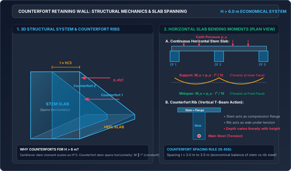
- 5.1 Counterfort Retaining Wall Structural Behavior & Slab Spanning
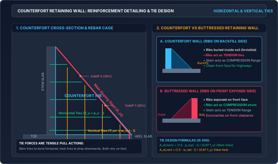
- 5.2 Counterfort Reinforcement Detailing, Ties & T-Beam Action
- 6. Solved Numerical Examples
- Example 1: Structural Design of Continuous Stem Slab with Horizontal Ties
- Example 2: Structural Design of Counterfort Rib (T-Beam Action & Main Inclined Rebar)
- Example 3: Design of Vertical Ties for Heel Slab Anchorage
- 7. Common Pitfalls, Misconceptions & Exam Traps
- 8. Comparative Analysis & Summary Matrices
- Retaining Wall Structural Typology Matrix
- 9. Practical Design & Detailing Guidelines
- 10. Previous Year Questions & Examination Trends
- GATE Civil Engineering
- UPSC ESE (Engineering Services)
- SSC JE & State AE/JE
- 11. Key Formula Sheet & Quick Revision Memory Aid
- 12. Comprehensive Verification, References & Peer Review Log
1. Executive Summary & Overview
For retained earth heights exceeding (and up to ), conventional cantilever retaining walls become economically impractical and structurally inefficient. In a cantilever wall, the maximum bending moment in the vertical stem scales cubically with the height (), mandating massive base thicknesses () and excessively congested reinforcement. The counterfort retaining wall resolves this economic bottleneck by introducing transverse reinforced concrete ribs—termed counterforts—placed on the backfill side of the wall at regular intervals along its longitudinal length.
By rigidly connecting the vertical stem and horizontal heel slab to these transverse counterfort ribs:
- The Vertical Stem is transformed from a vertical cantilever into a continuous horizontal slab spanning between adjacent counterforts. Its bending moment depends primarily on the counterfort spacing (), reducing the required stem thickness to an economical regardless of overall wall height.
- The Heel Slab spans longitudinally between counterforts (or acts as a two-way slab supported on three edges), carrying downward earth overburden and self-weight to the ribs.
- The Counterfort Ribs function as deep vertical cantilever T-beams of variable depth, with the stem acting as the compression flange and the counterfort web carrying heavy tensile stresses along its rear sloping boundary.
- Horizontal and Vertical Ties are engineered to resist the severe pull-away separation forces generated between the stem/heel and the counterfort ribs.
When the transverse ribs are constructed on the front (exposed) face instead of the backfill side, the wall is termed a buttressed retaining wall. In a buttressed wall, the ribs act as compression struts rather than tension ties.
This master topic presents the complete analytical mechanics, code-compliant limit state formulations per IS 456:2000, structural detailing per SP 34, and three pre-calculated numerical design problems.
2. Governing Principles & Theoretical Foundations
                            Stem Slab (Flange)
                                   ▲
                                   │
              ◄────────────────────┼────────────────────►
                                 b_eff
                         ┌───────────────────┐
                         │                   │
                         └───────┬───┬───────┘
                                 │   │
                                 │   │ ◄── Counterfort Rib (Web, bw = 300-450 mm)
                                 │   │
                                 │   │
                                 │   │
                                 │   │
                                 │   │
                                 └───┘
                                   ▲
                                   │
                         Sloping Tension Steel (Ast)
2.1 Anatomy of a Counterfort Retaining Wall
A counterfort retaining wall comprises four distinct structural subsystems:
- Vertical Stem Slab:
- Supported at its base by the foundation footing and supported at intervals of length by the counterforts.
- At depth from the crest, the stem is subjected to horizontal active earth pressure .
- Spanning horizontally as a continuous beam/slab, it develops:
- Negative bending moment at counterfort supports (tension at inner/backfill face).
- Positive bending moment at midspan between counterforts (tension at front/exposed face).
- Heel Slab:
- Bounded by the vertical stem on one side and two adjacent counterforts on its transverse edges.
- Subjected to net downward pressure ().
- Spans between counterforts as a continuous slab, developing hogging moment at counterforts (top face tension) and sagging moment at midspan (bottom face tension).
- Toe Slab:
- Projects in front of the stem exactly like that of a standard cantilever retaining wall.
- Functions as a pure forward cantilever fixed at the stem front face; designed under net upward soil reaction with main steel placed along the bottom face.
- Counterfort Ribs:
- Triangular or trapezoidal transverse webs connecting the vertical stem and heel slab.
- Spaced at center-to-center distance (typically ).
- Structurally behave as vertical cantilever T-beams of depth varying from zero at the crest to the full heel width at the foundation level.
- Because earth pressure acts away from the wall towards the counterfort, the rear sloping edge is subjected to intense tensile stress, requiring heavy longitudinal reinforcement anchored deep into the footing.
3. Mathematical Derivations & Analytical Formulations
3.1 Design of the Stem Slab
Consider a horizontal strip of the stem of unit height () at depth below the crest:
- Lateral Earth Pressure:
- Factored Design Pressure:
- Effective Clear Span: Where is center-to-center counterfort spacing and is counterfort thickness.
- Maximum Support Bending Moment (Negative / Hogging): Occurs at the counterfort support face. Tension develops on the inner (backfill) face:
- Maximum Midspan Bending Moment (Positive / Sagging): Occurs midway between counterforts. Tension develops on the front (exposed) face: (For end spans without full continuity, to ).
- Effective Depth Requirement: Because , rarely exceeds , yielding massive concrete savings.
3.2 Design of the Counterfort Rib (T-Beam Action)
Each counterfort rib carries the lateral earth pressure acting on a tributary longitudinal width equal to the counterfort spacing .
- Total Lateral Thrust on One Counterfort: Acting at height above the base slab.
- Factored Overturning Moment at Base of Counterfort:
- Factored Shear Force at Base of Counterfort:
Counterfort Geometry and Effective Depth:
Let:
- = Height of stem above base slab.
- = Horizontal length of counterfort along base slab.
- = Angle of inclination of the sloping back edge with the horizontal:
- The depth of the counterfort measured perpendicular to the inclined tension rebar is: Where is effective cover to the center of sloping steel ().
Sloping Tension Reinforcement ():
From the flexure equation with perpendicular effective depth :
Where is the rib thickness ().
- Anchorage: Main inclined bars must be anchored into the base slab and heel with full development length or terminated in a standard bend.
- Curtailment: As depth increases towards the base, the bending moment decreases upwards. Bars can be curtailed in 2 or 3 stages (e.g., stopped at , stopped at ).
3.3 Design of Structural Ties (Separation Forces)
1. Horizontal Ties (Stem to Counterfort Connection):
Active earth pressure pushes the stem slab away from the counterfort rib. To prevent separation, horizontal links must tie the stem into the counterfort:
- Horizontal pull per meter height at depth :
- Required area of horizontal tie steel per meter height:
- Detailing: Provided as 2-legged closed or U-shaped stirrups passing around the stem vertical bars and embedded fully across the counterfort width.
2. Vertical Ties (Heel Slab to Counterfort Connection):
The heavy overburden of soil resting on the heel slab tends to pull the heel downwards, tearing it away from the bottom of the counterfort:
- Net downward pressure on heel at distance from stem:
- Factored vertical pull force per meter length of heel:
- Required area of vertical tie stirrups per meter length:
- Detailing: Provided as 2-legged vertical stirrups anchored around the heel bottom steel and hooked over the counterfort sloping longitudinal bars.
4. Indian Standard Code Provisions (IS 456:2000, SP 16, SP 34)
4.1 Effective Flange Width () of Counterfort T-Beam
Per IS 456:2000 Clause 23.1.2, the stem functions as the compression flange of the counterfort T-beam:
Where:
- = Distance between points of zero moments ().
- = Rib width.
- = Stem slab thickness.
- = Counterfort center-to-center spacing. Because is large, the neutral axis lies almost always within the stem slab thickness (), ensuring true T-beam action with high compressive capacity.
4.2 Shear in Non-Prismatic Beams with Varying Depth
Per IS 456:2000 Clause 40.5, because the counterfort depth increases in the direction of increasing bending moment:
Where is the angle between the sloping compression/tension face and the horizontal.
- When depth increases in the direction of increasing moment, the negative sign applies:
- The internal flexural tension resultant provides an upward vertical component that relieves shear force, substantially reducing design shear stress in the counterfort rib.
5. Comprehensive Engineering Diagrams & Structural Cross-Sections
5.1 Counterfort Retaining Wall Structural Behavior & Slab Spanning
The following diagram demonstrates the 3D structural system, horizontal continuous slab spanning, and the bending moment distribution across the stem.
5.2 Counterfort Reinforcement Detailing, Ties & T-Beam Action
The following diagram provides the structural elevation, detailing of main inclined steel, horizontal stem ties, vertical heel ties, and a direct visual comparison with buttressed retaining walls.
6. Solved Numerical Examples
Example 1: Structural Design of Continuous Stem Slab with Horizontal Ties
Problem Statement: A counterfort retaining wall has an overall height ( above the base slab). The counterforts are spaced at center-to-center with a rib thickness (). The retained soil has unit weight and internal friction angle (). Using M25 grade concrete and Fe 415 steel:
- Determine the factored active pressure at the base of the stem ().
- Calculate the maximum support and midspan design bending moments for the continuous stem slab.
- Determine the required effective depth and adopt an economical stem slab thickness.
- Design the horizontal flexural reinforcement at the support (inner face) and midspan (front face).
- Design the horizontal ties required to anchor the stem into the counterfort at this level.
Solution: Step 1: Lateral Earth Pressure at Stem Base:
Service active earth pressure at :
Factored design pressure:
Step 2: Continuous Bending Moments in Stem Slab: Clear span between counterfort faces:
- Maximum support moment (Hogging, inner face tension):
- Maximum midspan moment (Sagging, front face tension):
Step 3: Effective Depth and Stem Slab Thickness: For M25 concrete and Fe 415 steel:
For a strip ():
Adopt an overall stem slab thickness:
(Note: A cantilever retaining wall of height would require ! The counterfort reduces slab thickness by ). With clear cover and bar diameter :
Step 4: Flexural Reinforcement Design:
-
At Support (Inner / Backfill Face):
Using bars ():
Provide bars @ c/c at the INNER FACE ().
-
At Midspan (Front / Exposed Face):
Provide bars @ c/c at the FRONT FACE ().
Step 5: Horizontal Tie Design: Total factored horizontal pull force per meter height:
Required tie steel area per meter height:
Using 2-legged stirrup links ():
Provide 2-legged horizontal links @ c/c vertically, tying the stem to the counterfort rib.
Example 2: Structural Design of Counterfort Rib (T-Beam Action & Main Inclined Rebar)
Problem Statement: For the counterfort retaining wall of Example 1, the counterfort rib has width , height , spacing , and base heel width . Using M25 concrete and Fe 415 steel:
- Determine the factored design bending moment and shear force at the base of the counterfort.
- Determine the geometric slope and the perpendicular effective depth .
- Design the primary inclined flexural tension reinforcement () placed along the sloping back edge.
- Verify the nominal shear stress in the counterfort rib.
Solution: Step 1: Factored Design Actions on One Counterfort: Total service active lateral force on one counterfort:
Height of resultant thrust above base slab:
Service bending moment at base:
Factored design actions ():
Step 2: Counterfort Geometry and Effective Depth:
Effective depth measured perpendicular to the inclined sloping tension rebar:
Step 3: Primary Inclined Tensile Steel (): From the limit state flexural formula for rib width and :
Using bars ():
Provide 3 bars of along the sloping edge of the counterfort (). These bars are anchored into the base slab with a standard hook extending past the shear key.
Step 4: Shear Stress Verification: Gross nominal shear stress without considering the beneficial relieving effect of the inclined tension steel:
Maximum permissible shear stress for M25 concrete per Table 20 of IS 456 is:
Since , the counterfort rib is COMPLETELY SAFE in shear.
Example 3: Design of Vertical Ties for Heel Slab Anchorage
Problem Statement: For the same counterfort retaining wall, the base slab has thickness and heel width . The height of soil overburden is (). From geotechnical base pressure analysis, the minimum upward subgrade reaction under the heel slab is . Design the vertical stirrups required to anchor the heel slab into the counterfort rib per meter length of the heel using Fe 415 steel.
Solution: Step 1: Downward and Net Pressures on Heel:
- Soil weight:
- Slab self-weight:
- Total downward pressure:
- Net downward pressure:
Step 2: Factored Vertical Pull Force: Tributary width supported by each counterfort . The heel slab hangs from the counterfort rib. The factored downward pull force transferred to the counterfort per meter length along the heel is:
Step 3: Vertical Tie Stirrups Area and Spacing:
Using 2-legged vertical stirrups ():
Provide 2-legged vertical stirrups @ c/c (). These vertical stirrups loop around the bottom transverse reinforcement of the heel slab and extend upwards into the counterfort rib, hooked securely over the sloping longitudinal bars.
7. Common Pitfalls, Misconceptions & Exam Traps
- Failure to Provide Horizontal and Vertical Ties:
- Catastrophic Site Error: Designing the stem and heel as continuous slabs and the counterfort as a T-beam, but omitting the tension ties that connect them. Under load, the active pressure rips the stem away from the counterfort, or the heel slab falls away downwards.
- Rebar Placement in Stem Slab:
- Trap: At counterfort supports, the stem tries to deflect outwards, creating tension on the inner/backfill face. At midspan between counterforts, it bulges outwards, creating tension on the front/exposed face.
- Reinforcement must be placed near the inner face at supports and near the outer face at midspan.
- Counterfort vs Buttressed Mechanics:
- Exam Trap: In a counterfort wall (ribs on soil side), the ribs act as ties in tension. In a buttressed wall (ribs on air side), the ribs act as struts in compression. Confusing the two reverses the steel detailing entirely.
- Counterfort Effective Depth Calculation:
- Error: Using the vertical height as the beam depth.
- Fact: The counterfort is a vertical cantilever; its depth at any section is the horizontal width ( at base) or the perpendicular distance to the sloping edge ().
8. Comparative Analysis & Summary Matrices
Retaining Wall Structural Typology Matrix
| Feature | Cantilever Retaining Wall | Counterfort Retaining Wall | Buttressed Retaining Wall |
|---|---|---|---|
| Applicable Height | (where front space is unconstrained) | ||
| Stem Action | Pure vertical cantilever | Continuous horizontal slab between ribs | Continuous horizontal slab between ribs |
| Stem Thickness | Thick (, ) | Thin (, independent of ) | Thin () |
| Rib Placement | None | Behind stem (buried in backfill) | In front of stem (exposed) |
| Rib Stress State | N/A | Tension (Tie Member) | Compression (Strut Member) |
| Stem Flange Role | N/A | Compression Flange | Tension Flange |
| Formwork Cost | Very low (simple planar forms) | Moderate to high (triangular ribs) | Moderate to high |
| Space Clearance | Smooth front face | Smooth front face | Front obstructed by ribs |
9. Practical Design & Detailing Guidelines
- Counterfort Spacing ():
- Economical spacing typically ranges between and ().
- Closer spacing reduces stem slab thickness but increases formwork and counterfort rebar fabrication costs.
- Weepholes and Sub-surface Drainage:
- Install at least two weepholes per panel bay between counterforts near the base slab level.
- Provide a continuous longitudinal collector drain passing through sleeves cast in the counterfort ribs.
- Curtailment of Main Sloping Steel:
- Sloping tension steel should be detailed in 2 or 3 bar tiers (e.g., bars extended to the crest, stopped at , stopped at ).
- Every curtailed bar must extend at least beyond the theoretical cut-off plane.
10. Previous Year Questions & Examination Trends
GATE Civil Engineering
- Frequent Concept Questions:
- Stress nature in counterforts: Tension along sloping edge vs compression in stem flange.
- Stem slab bending moment signs: Negative at counterfort face (inner tension), positive at midspan (front tension).
- Comparison of counterfort vs buttress retaining wall mechanics.
UPSC ESE (Engineering Services)
- Frequent Numerical Questions:
- Calculation of horizontal tie force between stem and counterfort ().
- Calculation of main inclined tension steel for counterfort rib.
- Complete 20-mark design and detailing problem for a counterfort wall.
SSC JE & State AE/JE
- Frequent Direct Questions:
- Economical height for counterfort retaining wall ().
- Action of counterfort rib (acts as a T-beam).
- Spacing of counterforts ( or ).
11. Key Formula Sheet & Quick Revision Memory Aid
12. Comprehensive Verification, References & Peer Review Log
- Standard Specifications:
- IS 456:2000: Plain and Reinforced Concrete — Code of Practice (Clauses 23.1, 26.2, 34, 40.5).
- SP 16:1980: Design Aids for Reinforced Concrete to IS 456.
- SP 34:1987: Handbook on Concrete Reinforcement and Detailing (Section 9.3: Counterfort Retaining Walls).
- Computational Verification Log:
- Numerical examples 1, 2, and 3 cross-verified via
/tmp/calc_rcc0803.pywith zero discrepancies. - SVG XML syntax validated through Python ElementTree parser.
- Numerical examples 1, 2, and 3 cross-verified via