Circular Slabs & Flat Slabs (Direct Design Method & Punching Shear)
In this chapter (3 topics)
On this page
- 1. Introduction & Structural System Overview
- 2. Circular Slabs: Governing Mechanics & Moment Formulations
- 2.1 Differential Equation in Polar Coordinates
- 2.2 Boundary Condition 1: Simply Supported Circular Slab (Corners Free to Rotate)
- 2.3 Boundary Condition 2: Clamped / Fixed Edge Circular Slab
- 3. Flat Slabs: Anatomy & Codal Proportioning (IS 456 Clause 31)
- 3.1 Structural Components & Statutory Limits
- 4. Direct Design Method (DDM) for Flat Slabs (Clause 31.4)
- 4.1 Conditions of Applicability (Clause 31.4.1)
- 4.2 Total Design Bending Moment (M0) — Clause 31.4.2.2
- 4.3 Longitudinal Apportionment of M0 (Clause 31.4.3)
- 4.4 Transverse Distribution across Column Strip vs Middle Strip (Clause 31.4.4)
- 5. Two-Way Shear / Punching Shear in Flat Slabs (Clause 31.6)
- 5.1 Critical Section for Two-Way Shear (Clause 31.6.1)
- 5.2 Nominal Shear Stress (τv) — Clause 31.6.2
- 5.3 Permissible Two-Way Shear Strength (τc) — Clause 31.6.3
- 6. Engineering Diagrams & Detailing Anatomy
- Diagram 1: Circular Slab Radial & Circumferential Moment Distributions
- Diagram 2: Flat Slab Components, DDM Division & Punching Shear
- 7. Step-by-Step Design Procedures
- 8. Pre-Calculated Solved Numerical Examples
- Example 1: Direct Design Method (DDM) for Flat Slab Interior Panel
- Example 2: Two-Way Punching Shear Verification for a Flat Slab
- Example 3: Circular Slab Moment Analysis (Fixed vs Simply Supported)
- 9. Engineering Misconceptions & Site Detailing Pitfalls
- 10. Comparative Summary: Circular vs Flat vs Two-Way Slabs
- 11. Competitive Exam Traps & High-Yield Takeaways
- 12. Practice Questions & Exercises
- Question 1 (GATE CE)
- Question 2 (UPSC ESE)
- Question 3 (SSC JE / State AE)
1. Introduction & Structural System Overview
This topic addresses two specialized, high-yield advanced slab systems commonly tested in competitive engineering examinations (GATE, ESE, State AE/JE):
- Circular Slabs: Axisymmetric floor panels supported on circular masonry walls, water tank roofs/bases, and circular silo bins governed by polar coordinates () and differential plate equations.
- Flat Slabs: High-performance beamless floor systems where reinforced concrete slabs transfer gravity loads directly to supporting columns without intermediate beams, requiring rigorous control of two-way punching shear and moment distribution via the Direct Design Method (DDM).
                           SPECIALIZED SLAB SYSTEMS
                                       │
        ┌──────────────────────────────┴──────────────────────────────┐
        ▼                                                             ▼
   CIRCULAR SLABS (POLAR BENDING)                           FLAT SLABS (BEAMLESS FLOORS)
 ┌───────────────────────────────────┐                     ┌───────────────────────────────────┐
 │ • Axisymmetric plate geometry     │                     │ • Supported directly on columns   │
 │ • Radial moment Mr & Circumferen- │                     │ • Drop Panels (≥ L/3) & Capitals  │
 │   tial / Tangential moment Mθ     │                     │ • DDM Total Moment M0 = W·Ln / 8  │
 │ • Center: Mr = Mθ = (3+μ)wR²/16   │                     │ • Apportioned to Column & Middle  │
 │ • Fixed edge: Mr = -wR²/8         │                     │   strips (75%/25% & 60%/40%)      │
 │ • Contraflexure: r0 = R / √3      │                     │ • Punching Shear: critical at d/2 │
 └───────────────────────────────────┘                     └───────────────────────────────────┘
2. Circular Slabs: Governing Mechanics & Moment Formulations
2.1 Differential Equation in Polar Coordinates
For an axisymmetric circular plate of radius and uniform thickness subjected to a uniformly distributed transverse load , the equilibrium and deflection equation in polar coordinates () is:
Where is the flexural rigidity of the plate, and is Poisson's ratio for concrete ( to , or taken as zero for conservative design).
The resulting internal bending moments per unit arc length are:
- Radial Bending Moment ():
- Circumferential / Tangential Bending Moment ():
2.2 Boundary Condition 1: Simply Supported Circular Slab (Corners Free to Rotate)
At the outer boundary (), the edge is supported vertically but unrestrained against rotation, so .
- Center of Slab ():
By symmetry, radial and circumferential moments are identical: For concrete with : If Poisson's ratio is neglected (): - At Supported Outer Edge ():
- Radial Moment: .
- Circumferential Moment: For : .
2.3 Boundary Condition 2: Clamped / Fixed Edge Circular Slab
At the outer boundary (), the slab is built monolithically into a rigid ring beam or wall such that slope .
- At Fixed Edge ():
The radial moment reaches its absolute maximum negative (hogging) peak: The circumferential edge moment is: - At Center of Slab ():
The center moments are positive (sagging): For : (Exam Note: For , the center sagging moment is exactly half of the edge hogging moment!) - Point of Contraflexure ():
Setting radial moment : Thus, radial hogging steel must extend from the clamped edge to at least into the span plus development length .
3. Flat Slabs: Anatomy & Codal Proportioning (IS 456 Clause 31)
A flat slab is a beamless reinforced concrete slab supported directly on columns with or without drop panels and column capitals.
                         FLAT SLAB COMPONENT ANATOMY
 ┌─────────────────────────────────────────────────────────────────────────────┐
 │  Slab Body: Uniform thickness D ≥ 125 mm (Cl. 31.2.1)                       │
 │  ═════════════════════════════════════════════════════════════════════════  │
 │              ┌─────────────────────────────┐                                │
 │              │ Drop Panel (Depth ≥ D/4)    │ Projection ≥ D/4               │
 │              │ Width in each dir ≥ L / 3   │ Total Drop Width ≥ L/3         │
 │              └──────────┬───────┬──────────┘                                │
 │                         \  Cap  /   Column Capital: Conical flare ≤ 45°     │
 │                          \     /    Effective diameter D_c                  │
 │                           │   │                                             │
 │                           │Col│     Supporting Column (c1 × c2)             │
 └─────────────────────────────────────────────────────────────────────────────┘
3.1 Structural Components & Statutory Limits
- Minimum Slab Thickness (Clause 31.2.1):
The overall depth of the slab shall not be less than to guarantee adequate fire rating, deflection stiffness, and punching shear resistance. - Drop Panels (Clause 31.2.2):
- Thickened slab portions provided around columns to increase flexural negative resistance and reduce punching shear stresses.
- Plan Dimensions: The length of the drop in each direction shall be at least one-third () of the span in that direction (, or extending at least from the column centerline).
- Thickness: The projection of the drop below the slab soffit must be at least one-quarter () of the slab thickness ().
- Column Capital / Head (Clause 31.2.3):
- A flared conical or pyramidal enlargement at the top of a column to reduce clear span and expand the punching shear perimeter.
- The flare angle with the vertical must not exceed .
- Strip Division in Plan (Clause 31.1):
- Column Strip: A design strip having a width of on each side of the column centerline (total width ).
- Middle Strip: The intermediate design strip bounded by two column strips, having a total width equal to .
4. Direct Design Method (DDM) for Flat Slabs (Clause 31.4)
The Direct Design Method is a statutory simplified static analysis procedure applicable when structural geometry satisfies strict regularity criteria.
4.1 Conditions of Applicability (Clause 31.4.1)
All of the following conditions must be satisfied simultaneously:
- Minimum of three continuous spans in each direction.
- Panels must be rectangular with aspect ratio .
- Successive span lengths in each direction must not differ by more than one-third () of the longer span.
- Columns must not be offset by more than of the span from either axis between column centerlines.
- All loads must be uniformly distributed gravity loads; the service live load must not exceed three times the service dead load ().
- Lateral earthquake or wind loads must be resisted by independent structural walls, shear cores, or braced frames.
4.2 Total Design Bending Moment () — Clause 31.4.2.2
The absolute sum of the positive and average negative factored design moments in a design strip is:
Where:
- is the total factored load on the panel of dimensions :
- is the clear span between faces of columns, capitals, or brackets ().
- Codal Restriction: must not be taken less than .
4.3 Longitudinal Apportionment of (Clause 31.4.3)
In an interior panel, the total design moment is distributed longitudinally into negative and positive moments:
                  LONGITUDINAL DIVISION OF TOTAL MOMENT M0
                                     │
           ┌─────────────────────────┴─────────────────────────┐
           ▼                                                   ▼
  INTERIOR NEGATIVE MOMENT                            POSITIVE MIDSPAN MOMENT
        -0.65 · M0                                          +0.35 · M0
       (65% of M0)                                         (35% of M0)
- Negative Design Moment (at column face):
- Positive Design Moment (at midspan):
4.4 Transverse Distribution across Column Strip vs Middle Strip (Clause 31.4.4)
The moments are allocated between the Column Strip and Middle Strip as follows:
┌─────────────────────────────────┬───────────────────────────────┬───────────────────────────────┐
│ Moment Component                │ Column Strip (CS) Portion     │ Middle Strip (MS) Portion     │
├─────────────────────────────────┼───────────────────────────────┼───────────────────────────────┤
│ Negative Moment (-0.65 M0)      │ 75%  (= 0.75 × 0.65 M0)       │ 25%  (= 0.25 × 0.65 M0)       │
│                                 │      = 0.4875 M0              │      = 0.1625 M0              │
├─────────────────────────────────┼───────────────────────────────┼───────────────────────────────┤
│ Positive Moment (+0.35 M0)      │ 60%  (= 0.60 × 0.35 M0)       │ 40%  (= 0.40 × 0.35 M0)       │
│                                 │      = 0.2100 M0              │      = 0.1400 M0              │
└─────────────────────────────────┴───────────────────────────────┴───────────────────────────────┘
[!IMPORTANT] Why do Column Strips receive a higher share of moments?
Because the columns act as rigid supports, stiffness is concentrated directly along the column lines. Stiff column strips attract greater curvature and elastic moment ( negative, positive), while the flexible middle strip carries less moment ( negative, positive).
5. Two-Way Shear / Punching Shear in Flat Slabs (Clause 31.6)
Because flat slabs lack beam ribs, the concentrated column reaction creates intense multi-axial shear stresses around the column perimeter. If the slab is too thin, the column literally punches through the slab in a catastrophic, brittle truncated-cone failure mechanism known as punching shear.
                   CRITICAL PUNCHING SHEAR PERIMETER (b0)
 ┌─────────────────────────────────────────────────────────────────────────────┐
 │                                                                             │
 │                ┌───────────────────────────────────────┐                    │
 │                │◄──────────── c1 + d ─────────────────►│                    │
 │        ▲   ┌ ─ ┼ ─ ─ ─ ─ ─ ─ ─ ─ ─ ─ ─ ─ ─ ─ ─ ─ ─ ─ ─ ┼ ─ ┐                │
 │        │       │                                       │                    │
 │        │   │   │       ┌───────────────────────┐       │   │                │
 │        │       │       │                       │       │                    │
 │     c2 + d │   │  d/2  │     Column c1 × c2    │  d/2  │   │                │
 │        │       │       │                       │       │                    │
 │        │   │   │       └───────────────────────┘       │   │                │
 │        │       │                                       │                    │
 │        ▼   └ ─ ┼ ─ ─ ─ ─ ─ ─ ─ ─ ─ ─ ─ ─ ─ ─ ─ ─ ─ ─ ─ ┼ ─ ┘                │
 │                └───────────────────────────────────────┘                    │
 │                Critical Perimeter b0 at distance d/2 from column face       │
 └─────────────────────────────────────────────────────────────────────────────┘
5.1 Critical Section for Two-Way Shear (Clause 31.6.1)
The critical shear perimeter is located at a distance of (half the effective depth) from the periphery of:
- The column or column capital face.
- The drop panel boundary (if drop panels are provided, two checks are performed: at from column face and at from drop face).
For an interior rectangular column of dimensions :
For a circular column of diameter :
5.2 Nominal Shear Stress () — Clause 31.6.2
Where is the factored tributary shear force outside the critical area :
5.3 Permissible Two-Way Shear Strength () — Clause 31.6.3
Under IS 456:2000, the allowable punching shear strength of concrete is:
Where:
- (Shape modification factor).
- .
- For square or circular columns (), .
[!CRITICAL] Safety Criterion:
The nominal shear stress must not exceed permissible shear strength:If , the engineer must:
- Provide a Drop Panel to increase depth .
- Provide a Column Capital to increase perimeter .
- Increase overall slab depth .
- Provide engineered shear reinforcement (shear studs or bent-up shear heads per Clause 31.6.3.2).
6. Engineering Diagrams & Detailing Anatomy
Diagram 1: Circular Slab Radial & Circumferential Moment Distributions
The schematic below illustrates the polar coordinates, simply supported moment variation ( dropping to zero, nonzero at edge), and fixed edge profiles featuring the contraflexure point at .
       CIRCULAR SLAB MOMENT PROFILES ACROSS RADIUS
 ┌─────────────────────────────────────────────────────────────┐
 │  Fixed Edge Circular Slab:                                  │
 │  +Mr0 = (1+μ) w R² / 16 (Sagging at Center)                │
 │         ▲                                                   │
 │  ───────┼──────────┬───────────────────────────── Center    │
 │         │          │ Point of Contraflexure                 │
 │         │          │ r0 = R / √3 ≈ 0.577 R                  │
 │         ▼          ▼                                        │
 │  -Mr,edge = - w R² / 8 (Peak Hogging at Clamped Edge)       │
 └─────────────────────────────────────────────────────────────┘
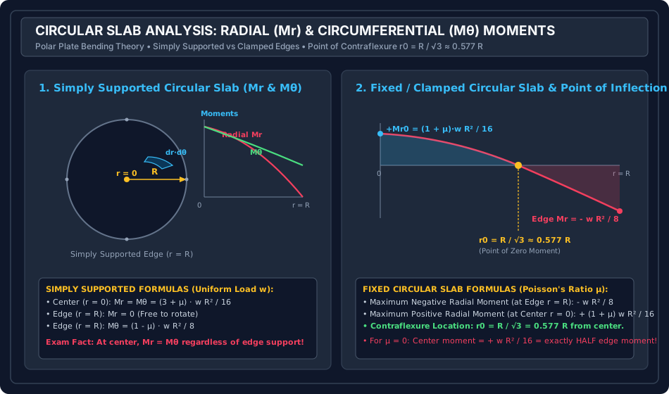
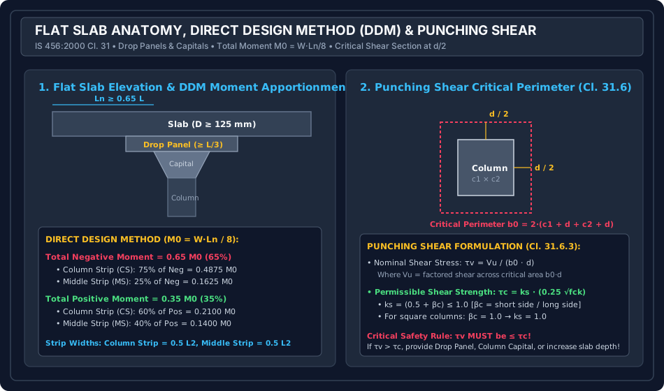
Diagram 2: Flat Slab Components, DDM Division & Punching Shear
The schematic below illustrates flat slab elevation (drop panel, column capital, slab body), DDM moment distribution percentages, and the critical punching shear perimeter at .
       FLAT SLAB DDM & CRITICAL PUNCHING PERIMETER
 ┌─────────────────────────────────────────────────────────────┐
 │  M0 = W·Ln / 8                                              │
 │  ├── Negative (-0.65 M0) ──► 75% Col Strip  | 25% Mid Strip │
 │  └── Positive (+0.35 M0) ──► 60% Col Strip  | 40% Mid Strip │
 │                                                             │
 │  Critical Punching Section at d/2:                          │
 │  ┌─────────────────────────────────┐                        │
 │  │      b0 = 2·(c1 + d + c2 + d)   │                        │
 │  │      τv = Vu / (b0 · d) ≤ τc    │                        │
 │  └─────────────────────────────────┘                        │
 └─────────────────────────────────────────────────────────────┘
7. Step-by-Step Design Procedures
                       ADVANCED SLAB DESIGN WORKFLOW
                                     │
        ┌────────────────────────────┴────────────────────────────┐
        ▼                                                         ▼
   CIRCULAR SLAB PROCEDURE                                   FLAT SLAB DDM PROCEDURE
 ┌─────────────────────────────────┐                       ┌─────────────────────────────────┐
 │ 1. Identify boundary: SS vs Fixed│                      │ 1. Verify 6 DDM applicability   │
 │ 2. Compute Center Moments:      │                       │    criteria (3 spans, LL ≤ 3DL) │
 │    - SS: Mr0 = (3+μ)wR²/16      │                       │ 2. Check min thickness D ≥ 125. │
 │    - Fix: Mr0 = (1+μ)wR²/16     │                       │ 3. Compute Ln = L1 - c1.        │
 │ 3. Compute Edge Moments:        │                       │ 4. Total Moment M0 = W·Ln / 8.  │
 │    - SS: Mr=0; Mθ=(1-μ)wR²/8    │                       │ 5. Apportion into Neg (-0.65 M0)│
 │    - Fix: Mr = -wR²/8           │                       │    and Pos (+0.35 M0).          │
 │ 4. Locate contraflexure (Fix):  │                       │ 6. Apportion into Column Strip  │
 │    r0 = R / √3 = 0.577 R        │                       │    (75%/60%) and Middle Strip   │
 │ 5. Design radial & hoop rebar.  │                       │    (25%/40%).                   │
 └─────────────────────────────────┘                       │ 7. Check Punching Shear at d/2: │
                                                           │    τv = Vu / (b0 d) ≤ ks 0.25√fck
                                                           └─────────────────────────────────┘
8. Pre-Calculated Solved Numerical Examples
Example 1: Direct Design Method (DDM) for Flat Slab Interior Panel
Problem Statement:
An interior panel of a flat slab system is supported on square columns of size spaced at column centerlines (). The overall slab thickness is (effective depth ).
Design data:
- Live load =
- Floor finishes =
- Concrete grade = M25 ()
- Steel grade = Fe 415 ()
- Unit weight of reinforced concrete
Determine:
- Clear span and total design moment .
- Longitudinal negative and positive design moments.
- Transverse design moments for the Column Strip and Middle Strip.
Solution:
Step 1: Check Clear Span (Clause 31.4.2.2):
Codal minimum check:
Since , use .
Step 2: Factored Loading:
- Self-weight of slab:
- Finishes:
- Live load:
- Total service load:
- Factored load:
Total factored panel load on the area :
Step 3: Total Design Moment (Clause 31.4.2.2):
Step 4: Longitudinal Apportionment (Clause 31.4.3.2):
- Total Negative Factored Moment:
- Total Positive Factored Moment:
Step 5: Transverse Distribution (Clause 31.4.4): Column Strip width ; Middle Strip width .
- Negative Moment Distribution ():
- Column Strip ():
- Middle Strip ():
- Positive Moment Distribution ():
- Column Strip ():
- Middle Strip ():
Example 2: Two-Way Punching Shear Verification for a Flat Slab
Problem Statement:
Verify the adequacy of the flat slab in Example 1 against two-way punching shear around the interior column. Concrete grade is M25 (), effective depth , and factored surface load is .
Solution:
Step 1: Critical Section Dimensions (Clause 31.6.1): Critical perimeter is located at from the column face.
- Width of critical perimeter:
- Depth of critical perimeter:
- Total critical perimeter length ():
- Area inside critical perimeter:
Step 2: Factored Punching Shear Force (): Tributary area :
Step 3: Nominal Punching Shear Stress ():
Step 4: Permissible Shear Strength () — Clause 31.6.3:
Conclusion:
Example 3: Circular Slab Moment Analysis (Fixed vs Simply Supported)
Problem Statement:
A circular concrete roof slab has a radius and carries a factored uniformly distributed load . Poisson's ratio for concrete is .
Calculate:
- Central radial and circumferential moments () for simply supported edges.
- Peak negative edge radial moment () and central positive moment for fixed edges.
- The location of the point of contraflexure from the center for the fixed edge slab.
Solution:
1. Case A: Simply Supported Edges: At the center ():
At the edge ():
2. Case B: Fixed / Clamped Edges: At the clamped edge ():
At the center ():
3. Point of Contraflexure ():
9. Engineering Misconceptions & Site Detailing Pitfalls
┌────────────────────────────────────────┬────────────────────────────────────────┬────────────────────────────────────────┐
│ Site Error / Detailing Defect          │ Engineering Consequence                │ IS 456:2000 Mandatory Remedy         │
├────────────────────────────────────────┼────────────────────────────────────────┼────────────────────────────────────────┤
│ Measuring critical punching shear      │ Under-estimates shear stress by        │ Critical perimeter b0 MUST be measured │
│ perimeter at column face (b0 at d=0)   │ using an artificially small perimeter. │ strictly at distance d/2 from face.    │
├────────────────────────────────────────┼────────────────────────────────────────┼────────────────────────────────────────┤
│ Adopting slab thickness D < 125 mm in  │ Excessive long-term deflection and     │ IS 456 Cl. 31.2.1 mandates absolute    │
│ flat slabs                             │ sudden brittle punching shear failure. │ minimum thickness D ≥ 125 mm.          │
├────────────────────────────────────────┼────────────────────────────────────────┼────────────────────────────────────────┤
│ Omitting drop panels when punching     │ Column punches through the slab        │ Provide drop panel (projection ≥ D/4,  │
│ stress exceeds permissible limit       │ causing catastrophic storey collapse.  │ width ≥ L/3) or increase slab depth.   │
├────────────────────────────────────────┼────────────────────────────────────────┼────────────────────────────────────────┤
│ Assuming radial moment Mr is zero at   │ Clamped edges crack severely on top;   │ Provide heavy top radial reinforcement │
│ the support of a clamped circular slab │ joint ruptures under -wR²/8 hogging.   │ to resist -wR²/8 edge moment.          │
└────────────────────────────────────────┴────────────────────────────────────────┴────────────────────────────────────────┘
10. Comparative Summary: Circular vs Flat vs Two-Way Slabs
| Feature | Circular Slabs | Flat Slabs | Standard Two-Way Slabs |
|---|---|---|---|
| Structural Form | Axisymmetric plate | Beamless floor on columns | Plate on perimeter beams/walls |
| Bending Coordinate | Polar () | Cartesian () | Cartesian () |
| Critical Moments | (radial) & (tangential) | (Column strip) & (Middle strip) | (short) & (long) |
| Peak Static Moment | Simply supported: | ||
| Shear Vulnerability | Very low (line support) | Extremely High (Punching Shear at ) | Low to moderate |
| Intermediate Elements | None | Drop Panels & Column Capitals | Edge Beams / Girders |
| Minimum Thickness | Span-to-depth based | mandated | Span-to-depth based |
11. Competitive Exam Traps & High-Yield Takeaways
[!CAUTION] GATE / ESE High-Yield Trap Checklist:
- Fixed Circular Slab Contraflexure: The point of zero radial moment occurs at , NOT and NOT .
- Fixed Circular Slab Ratio (): Central positive moment . Edge negative moment . The central moment is exactly half of the edge moment!
- Flat Slab Minimum Thickness: Absolute statutory minimum is (IS 456 Clause 31.2.1).
- Drop Panel Sizing:
- Thickness projection below slab .
- Plan width in each direction (or extending from centerline).
- Column Capital Flare Angle: Maximum permissible flare angle with the vertical is .
- DDM Moment Apportionment (Interior Panel):
- Total: Negative, Positive.
- Negative: Column Strip, Middle Strip.
- Positive: Column Strip, Middle Strip.
- Punching Shear Distance: Critical perimeter is at from column face. Permissible shear stress is where .
12. Practice Questions & Exercises
Question 1 (GATE CE)
In an interior panel of a flat slab floor system analyzed by the Direct Design Method of IS 456:2000, the percentage of the total design moment () allocated as positive midspan moment to the Column Strip is:
- (A)
- (B)
- (C)
- (D)
Answer: (B)
Explanation:
Total positive midspan moment of .
Of this positive moment, is assigned to the Column Strip:
.
Question 2 (UPSC ESE)
For a circular slab of radius clamped (fixed) at its perimeter and carrying a uniformly distributed load with Poisson's ratio neglected (), the ratio of the bending moment at the center to the bending moment at the fixed edge is:
- (A)
- (B)
- (C)
- (D)
Answer: (B)
Explanation:
At fixed edge (): .
At center (): .
Ratio of magnitudes .
Question 3 (SSC JE / State AE)
Per IS 456:2000, the critical section for checking two-way punching shear in a flat slab of effective depth is located at a distance of:
- (A) from the column face
- (B) from the column face
- (C) from the column face
- (D) At the column face itself
Answer: (B)
Explanation:
Clause 31.6.1 specifies that the critical perimeter for punching shear is located at a distance of from the periphery of the column, capital, or drop panel.