Combined Footings and Raft Foundations (Rectangular, Trapezoidal, Strap & Mat Systems)
In this chapter (3 topics)
On this page
- 1. Introduction to Combined Foundations
- 2. Structural Classification & Selection Criteria
- 3. Rectangular Combined Footings: Proportioning for Uniform Pressure
- 3.1 Step-by-Step Sizing Procedure
- 4. Longitudinal Structural Analysis of Rectangular Combined Footings
- 4.1 Factored Distributed Upward Load wu
- 4.2 Shear Force Distribution and Point of Zero Shear
- 4.3 Transverse Bending Analysis
- 5. Trapezoidal Combined Footings: Centroid Alignment
- 5.1 Governing Geometric Equations
- 5.2 Solution for Dimensions a and b
- 6. Strap (Cantilever) Footings: Structural Mechanics & Lever Arm
- 6.1 System Anatomy
- 6.2 Equilibrium Mechanics and Reactions
- 6.3 Design of the Strap Beam
- 7. Raft (Mat) Foundations: Structural Typologies & IS 2950 Design Criteria
- 7.1 Structural Typologies per IS 2950 (Part 1):1981
- 7.2 Modulus of Subgrade Reaction (ks) & Rigidity Criteria
- 8. Detailed Engineering Diagrams & Visual Walkthrough
- Figure 1: Combined Footings: Rectangular vs Trapezoidal Mechanics
- Figure 2: Strap Footings & Raft Foundation Structural Systems
- 9. Pre-Calculated Solved Numerical Examples
- Problem 1: Complete Design and Longitudinal Moments of a Rectangular Combined Footing
- Problem 2: Sizing of a Trapezoidal Combined Footing
- Problem 3: Equilibrium and Bending Moments of a Strap Footing
- 10. Comprehensive Comparison Table: Combined Foundation Systems
- 11. Practical Detailing and Common Field Pitfalls
- 12. Competitive Examination Traps & Quick Formula Sheet
- Common Exam Traps
- Master Formula Sheet
- 13. Practice Problems
- Problem 1 (GATE CE Format - NAT)
- Problem 2 (UPSC ESE Format - Multiple Choice)
- Problem 3 (State AE / SSC JE Format)
1. Introduction to Combined Foundations
In structural engineering, while isolated pad footings are the standard economical choice for independent columns, practical site boundaries, architectural column layouts, and poor soil conditions often make isolated footings unfeasible:
- Property Line (Boundary) Restrictions: When a column is located directly on a property line, boundary wall, or existing structure, an isolated footing cannot extend outward without encroaching on adjacent property. Placing the column on the edge of an isolated footing introduces heavy eccentricity, leading to severe edge stress concentration and potential overturning.
- Proximity of Columns & Overlapping Stress Bulbs: When two adjacent columns carry heavy loads and are closely spaced, their required isolated footing areas overlap, or their subterranean Boussinesq pressure bulbs intersect, causing excessive interactive settlement.
- Differential Settlement Mitigation: When two columns carry unequal loads on compressible soils, connecting them with a common rigid footing balances soil contact pressures and drastically curtails relative differential settlement.
- Low Geotechnical Bearing Capacity: When the cumulative area required for isolated footings exceeds approximately of the total building footprint area, a continuous raft (mat) foundation supporting all building columns becomes more economical and structurally superior.
       Isolated Overlap Problem:                   Combined Footing Solution:
         Col 1        Col 2                          Col 1        Col 2
          │            │                              │            │
       ┌──┴──┐      ┌──┴──┐                        ┌──┴────────────┴──┐
       │     │Overlap│    │                        │   Continuous     │
       └─────┼──────┼─────┘                        │   Rigid Slab     │
             └──────┘                              └──────────────────┘
2. Structural Classification & Selection Criteria
Depending on geometric constraints, column load ratios, and relative column positions, combined foundations are classified into four major structural systems:
| Foundation Type | Geometric / Site Condition | Load Relationship | Structural Behavior |
|---|---|---|---|
| Rectangular Combined Footing | Sufficient space available to extend footing beyond interior column | Exterior load Interior load | Inverted continuous slab-beam supported at two column points; uniform soil pressure. |
| Trapezoidal Combined Footing | Length is strictly restricted on both sides, or exterior column is heavier | Exterior load Interior load | Centroid shifted toward heavier column by tapering width from to . |
| Strap (Cantilever) Footing | Large distance between columns, making continuous combined slab uneconomical | Exterior column on property line | Two isolated footings connected by a rigid, non-bearing concrete beam that balances overturning. |
| Raft (Mat) Foundation | Total column footing area of footprint, or highly variable/weak soil | Multiple columns across 2D grid | Continuous thick concrete slab or slab-beam mat covering the entire substructure. |
3. Rectangular Combined Footings: Proportioning for Uniform Pressure
To prevent uneven settlement and structural twisting, combined footings are proportioned so that the centroid of the footing plan area coincides exactly with the resultant of the column loads (). This achieves a uniform upward soil reaction:
        ◄────────────────────────────── Length L ──────────────────────────────►
       ┌───────────────────────────────┬───────────────────────────────────────┐
       │                               │ Resultant R                           │
       │   Col 1 (Exterior)            │ (Centroid L/2)       Col 2 (Interior) │
       │   ┌────┐                      │                      ┌────┐           │
       │   │ P1 │                      │                      │ P2 │           │
Width B│   └────┘                      │                      └────┘           │
       │                               │                                       │
       └───────────────────────────────┴───────────────────────────────────────┘
       ▲   ◄──── x_bar ───────────────►▲
       │   ◄───────────── Spacing S ─────────────────────────►│
       Property Line (x_R from edge)
3.1 Step-by-Step Sizing Procedure
- Total Vertical Service Load: Including estimated self-weight of the footing and overburden:
- Required Footing Plan Area: Where is the safe bearing capacity of the soil.
- Position of Resultant Force from Column 1 Center: Taking moments about the center of Column 1: Where is the center-to-center spacing between Column 1 and Column 2.
- Distance of Resultant from Property Line (): If Column 1 has width along the length and its outer face is on the property line:
- Total Footing Length for Uniform Soil Pressure: Because the centroid of a rectangle lies at mid-length (), setting yields:
- Required Footing Width :
- Cantilever Overhang beyond Column 2 ():
4. Longitudinal Structural Analysis of Rectangular Combined Footings
Structurally, a combined footing acts as an inverted continuous beam supported on the two columns and loaded by the upward net factored soil pressure.
4.1 Factored Distributed Upward Load
Using factored ultimate loads and :
The upward distributed load per unit length of the footing is:
Elevation & Structural Actions:
       P_u1                                                     P_u2
        │                                                        │
        ▼                                                        ▼
     ┌──────┐                                                 ┌──────┐
     │ Col1 │                                                 │ Col2 │
   ──┴──────┴─────────────────────────────────────────────────┴──────┴──
   ▲                                                                   ▲
   └──────────────────────── wu = qu · B ──────────────────────────────┘ (Upward)

Longitudinal Bending Moment:
                  ▲ Hogging Moment (Top face in tension!)
                 / \
   ─────────────/───\─────────────────────────────────────────────────── (Zero line)
   \           /     \           /
    \_________/       \_________/
   Sagging at Col 1   Sagging at Col 2
4.2 Shear Force Distribution and Point of Zero Shear
- Starting from the left exterior edge ():
- Overhang to Column 1 face: Shear increases linearly upward to .
- At Column 1 centerline, the concentrated downward load acts:
- Point of Zero Shear (): The shear force passes through zero between Column 1 and Column 2 at distance from the left property edge:
- Maximum Negative (Hogging) Bending Moment: The maximum bending moment occurs at the point of zero shear ():
[!CRITICAL] Rebar Placement in Combined Footings: In isolated footings, main reinforcement is always placed at the bottom. In combined footings, between the columns, the footing bends upward like an inverted beam. This induces severe tensile stresses in the TOP face of the slab. Therefore, heavy longitudinal tensile reinforcement must be provided at the TOP of the footing slab, while bottom reinforcement is provided under the columns and along outer cantilever overhangs!
4.3 Transverse Bending Analysis
In the transverse direction (across width ), the footing acts as a cantilever projecting outward from the column faces on either side:
- The column load is dispersed across an effective transverse longitudinal band of width:
- Factored transverse bending moment at the column face:
- Transverse bottom reinforcement is placed in localized bands beneath each column.
5. Trapezoidal Combined Footings: Centroid Alignment
When the exterior column carries a significantly heavier load than the interior column (), the resultant force falls close to the exterior property line (). If a rectangular footing were used, achieving would restrict length so severely that the required width would become impossibly wide, or the footing would fail to reach Column 2! In such cases, a Trapezoidal Combined Footing is mandatory:
- Width at heavier exterior end:
- Width at lighter interior end: ()
- Total length: (fixed by site boundaries)
                       ◄────────────── Fixed Length L ──────────────►
                      ┌──────────────────────────────────────────────┐
                      │\                                            /│
                      │ \                  • Centroid (x_R)        / │
              Width a │  \                   (Resultant R)        /  │ Width b
             (Heavier)│   \                                      /   │ (Lighter)
                      │    \                                    /    │
                      │     \                                  /     │
                      └──────┴────────────────────────────────┴──────┘
5.1 Governing Geometric Equations
- Plan Area Equation:
- Centroid Location Equation: The distance of the centroid from the wider face must coincide with the resultant position :
5.2 Solution for Dimensions and
Rearranging the centroid equation:
Let and :
Subtracting :
[!NOTE] Boundary Limits for a Valid Trapezoid: For a physically realizable trapezoid ( and ):
- If (collapses to a rectangle).
- If (collapses to a triangle).
- If (impossible geometry; a strap footing must be used instead!).
6. Strap (Cantilever) Footings: Structural Mechanics & Lever Arm
When the distance between an exterior property-line column and an interior column is large (), a continuous combined footing slab requires massive concrete volume and deep sections to resist huge hogging moments. A Strap (Cantilever) Footing provides an elegant, highly economical alternative:
    Property Line
         │
       Col 1 (P1)                                           Col 2 (P2)
         │                                                      │
         ▼                                                      ▼
      ┌──────┐                    RIGID STRAP BEAM           ┌──────┐
      │      ├───────────────────────────────────────────────┤      │
   ───┴──────┴───                                         ───┴──────┴───
   ▲  Footing 1  ▲       (NO SOIL CONTACT UNDER STRAP)    ▲  Footing 2  ▲
   └─── R1 ──────┘                                        └─── R2 ──────┘
    ◄──── L1 ───►                                          ◄──── L2 ───►
6.1 System Anatomy
- Footing 1 (Exterior): Built directly beneath the exterior column on the property line. Because the column is at the outer edge, the soil reaction acts at the footing centroid (distance from boundary), creating an eccentricity .
- Footing 2 (Interior): A standard concentric isolated pad footing centered beneath Column 2.
- The Strap Beam: A narrow, deep, infinitely rigid reinforced concrete beam connecting Column 1 and Column 2.
- Crucial Rule: The strap beam does NOT bear on the soil. The earth beneath the strap is left uncompacted or cleared with an air gap.
- The strap beam acts as a rigid cantilever lever arm, transferring the overturning moment to the interior column.
6.2 Equilibrium Mechanics and Reactions
Taking moments about the centroid of Footing 2 (Column 2 center):
- Let be the center-to-center column spacing.
- The lever arm between Footing 1 centroid and Column 2 center is:
- Moment equilibrium about Footing 2: Since , the soil reaction on the exterior footing is greater than the column load ().
- Vertical equilibrium: The soil reaction on the interior footing is reduced by the upward reaction of the strap beam ().
6.3 Design of the Strap Beam
The strap beam is subjected to a constant shear force and a linear negative bending moment:
- Factored shear force in the strap beam:
- Maximum bending moment in the strap beam (at Column 1 center):
- Because pushes upward while pushes downward, the strap beam bends with tension in the top face.
- Heavy longitudinal reinforcement is detailed at the TOP of the strap beam, fully anchored with standard hooks into Column 1 and Column 2.
7. Raft (Mat) Foundations: Structural Typologies & IS 2950 Design Criteria
A raft foundation is a combined footing that covers the entire footprint beneath all structural walls and columns.
7.1 Structural Typologies per IS 2950 (Part 1):1981
- Flat Plate Raft: A solid concrete slab of uniform depth (). Simple to excavate and shutter; used for light to medium building loads.
- Flat Plate with Column Pedestals / Thickened Slabs: Slabs thickened beneath columns to resist high punching shear without thickening the entire floor mat.
- Beam-and-Slab (Ribbed) Raft: Inverted T-beam ribs running in orthogonal directions with a thinner bottom slab. Provides high flexural rigidity with reduced concrete volume; ideal for heavy column loads.
- Cellular (Hollow Box) Raft: Two solid slabs (top basement floor slab and bottom foundation slab) interconnected by longitudinal and transverse concrete web walls. Extremely rigid; minimizes differential settlement in deep clay strata and acts as a buoyant foundation.
Flat Plate:                     Beam-and-Slab (Ribbed):           Cellular (Hollow Box):
  │     │     │                   │     │     │                 │     │     │
┌─┴─────┴─────┴─┐               ┌─┴─────┴─────┴─┐             ┌─┴─────┴─────┴─┐ Top Slab
│               │               │ ┌─┐ ┌─┐ ┌─┐   │             │ █   █   █   █ │ Web Walls
└───────────────┘               └─┴─┴─┴─┴─┴─┴───┘             └─┴───┴───┴───┴─┘ Bottom Slab
7.2 Modulus of Subgrade Reaction () & Rigidity Criteria
Per IS 2950 (Part 1), the interaction between the raft slab and the supporting soil is characterized by the modulus of subgrade reaction :
Where is the contact soil pressure and is the vertical settlement.
Raft Rigidity Parameter
The relative stiffness of the raft slab relative to the supporting soil is quantified by the characteristic parameter :
Where:
- is the modulus of elasticity of concrete.
- is the moment of inertia of the raft strip per unit width.
- is the strip width.
Rigidity Test:
- Rigid Raft Analysis: If the column spacing satisfies: The raft can be analyzed using the Conventional Rigid Method. Soil pressure is assumed to vary linearly across the planar base:
- Flexible Raft Analysis: If , the raft flexes significantly between columns. Analysis must be performed using the Flexible (Winkler Spring) Method or finite element plate-bending software.
8. Detailed Engineering Diagrams & Visual Walkthrough
Figure 1: Combined Footings: Rectangular vs Trapezoidal Mechanics
The diagram below illustrates the structural layout, soil reaction, SFD, and BMD of a rectangular combined footing (highlighting the critical zero-shear location and hogging moment), along with the geometric parameters of a trapezoidal combined footing.
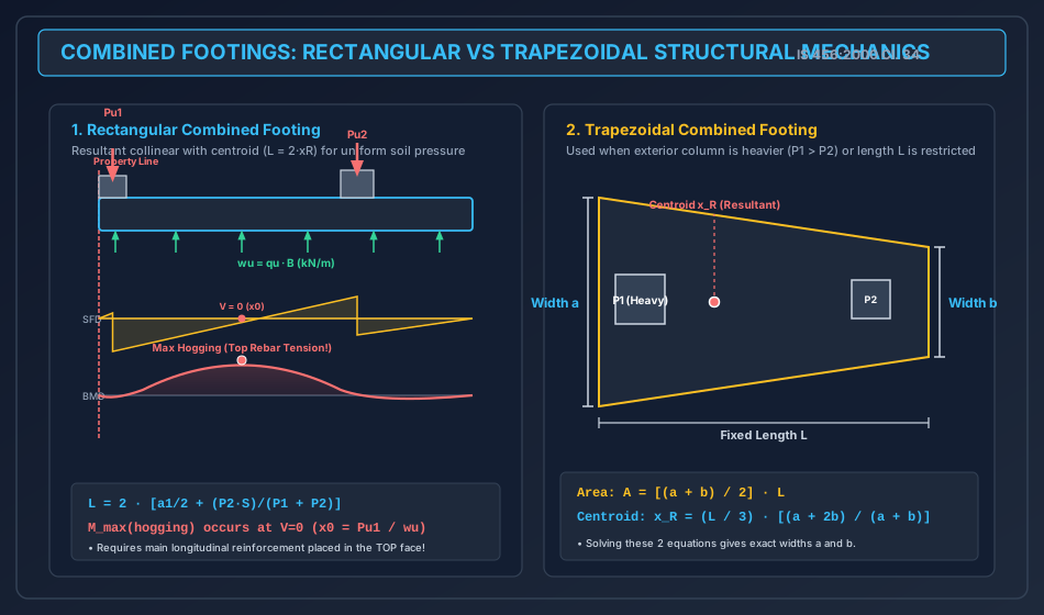
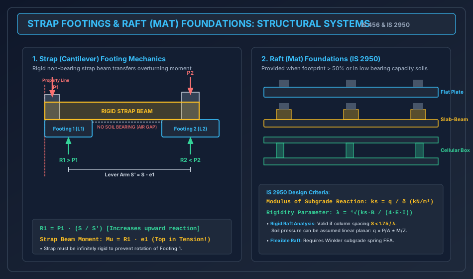
Figure 2: Strap Footings & Raft Foundation Structural Systems
The diagram below details the mechanics of a strap (cantilever) footing, showing the non-bearing gap beneath the strap and the reaction formulas, alongside cross-sections of the three primary raft foundation typologies (flat plate, beam-and-slab, cellular).
9. Pre-Calculated Solved Numerical Examples
Problem 1: Complete Design and Longitudinal Moments of a Rectangular Combined Footing
Statement: Two columns are spaced center-to-center.
- Column 1 (exterior, outer face on property boundary): , carrying service load ().
- Column 2 (interior): , carrying service load (). The safe bearing capacity of the soil is .
- Determine the length and width of a rectangular combined footing for uniform soil pressure.
- Determine the factored upward soil load intensity ().
- Locate the point of zero shear between the columns.
- Calculate the maximum negative (hogging) bending moment .
Solution:
Step 1: Footing Plan Sizing
- Total service load with self-weight:
- Required plan area:
- Resultant position from Column 1 center:
- Distance of resultant from property line (left edge of footing):
- Footing length for uniform soil pressure:
- Required width:
- Overhang beyond Column 2 center:
Step 2: Factored Upward Soil Load Intensity
Factored column loads: , .
Net factored upward soil pressure:
Upward load per meter length:
Step 3: Location of Point of Zero Shear ()
Taking as distance from the left property boundary edge:
Distance from Column 1 center:
Step 4: Maximum Negative (Hogging) Bending Moment
Conclusion: The maximum design moment is a hogging moment of , requiring primary longitudinal tensile reinforcement placed in the top face of the footing slab.
Problem 2: Sizing of a Trapezoidal Combined Footing
Statement: Two columns are spaced center-to-center.
- Exterior Column 1: Service load .
- Interior Column 2: Service load . Property boundary limits the footing so it cannot extend more than beyond the center of Column 1. The total length of the footing is strictly restricted to . Safe bearing capacity of soil .
- Explain why a rectangular footing is impossible.
- Determine the widths (wider end) and (narrower end) of a trapezoidal footing for uniform soil pressure.
Solution:
Step 1: Check Feasibility of a Rectangular Footing
- Total service load with self-weight:
- Required area:
- Resultant position from Column 1 center:
- Distance of resultant from left boundary:
- For a rectangular footing of length , the centroid is fixed at:
- Because , a rectangular footing would experience massive eccentricity (), causing severe non-uniform pressure.
- Therefore, a TRAPEZOIDAL FOOTING is mandatory.
Step 2: Solve for Trapezoidal Dimensions and
Using the two simultaneous governing equations:
- Area Equation:
- Centroid Equation:
- Subtracting from :
Conclusion: The trapezoidal footing has:
- Wider edge near Column 1:
- Narrower edge near Column 2:
- Length: (Area , Centroid at , matching resultant perfectly).
Problem 3: Equilibrium and Bending Moments of a Strap Footing
Statement: An exterior column on a property line carries a service load (). An interior column carries a service load (). The columns are spaced apart. The exterior footing is restricted in length to . Safe bearing capacity .
- Calculate the soil reaction on the exterior footing and on the interior footing.
- Size both footings.
- Calculate the maximum factored bending moment and shear force in the connecting strap beam.
Solution:
Step 1: Equilibrium and Soil Reactions
- Column 1 center is at from the property line.
- Centroid of Footing 1 () is at from the property line.
- Eccentricity of Column 1 on Footing 1:
- Effective lever arm between Footing 1 centroid and Column 2 center:
- Taking moments about Column 2:
- Vertical equilibrium:
Step 2: Sizing Footing 1 and Footing 2
- Footing 1 (Exterior):
- Footing 2 (Interior):
Step 3: Design Forces on the Strap Beam
- Factored column load: .
- Factored soil reaction: .
- Factored Shear Force in Strap Beam:
- Maximum Factored Bending Moment in Strap Beam: The strap beam resists the overturning moment produced by the eccentric reaction:
10. Comprehensive Comparison Table: Combined Foundation Systems
| Feature / Criteria | Rectangular Combined Footing | Trapezoidal Combined Footing | Strap (Cantilever) Footing | Raft (Mat) Foundation |
|---|---|---|---|---|
| Typical Column Spacing | Close to medium () | Close to medium () | Large () | Multiple orthogonal bays |
| Column Load Relation | Exterior Interior | Exterior Interior | Exterior or | Variable column loads |
| Property Line Constraint | Space available past Col 2 | Space restricted past Col 2 | Severe boundary restriction | Property-wide footprint |
| Soil Contact Area | Continuous rectangular slab | Continuous trapezoidal slab | Two isolated pads only | Single continuous mat |
| Strap Beam Required? | No | No | Yes (Rigid, Non-Bearing) | Integral ribs in slab-beam |
| Governing Moment | Hogging between columns (Top) | Hogging between columns (Top) | Hogging in strap beam (Top) | Two-way sagging & hogging |
| Differential Settlement | Low | Low | Very Low | Minimal (High stiffness) |
| Formwork Complexity | Low (Rectangular) | Moderate (Slanted forms) | Moderate (Deep strap beam) | High (For cellular/ribbed) |
11. Practical Detailing and Common Field Pitfalls
- The Top Steel Curtailment Trap:
- In combined footings, designers often assume that because it is a "footing," bottom steel is primary.
- Overlooking the huge top hogging bending moment causes catastrophic shear/flexural failure between columns. Top bars must be continuous and detailed with full tension lap splices.
- Soil Contact beneath Strap Beams:
- A strap beam is designed based on the fundamental assumption that it transfers pure shear and moment without direct soil contact.
- If contractors cast the strap beam directly on hard, unyielding soil, upward soil pressure develops under the strap, altering the reaction distribution and overstressing the interior footing.
- Trapezoidal Formwork Errors:
- When constructing trapezoidal footings, site engineers must ensure that the wider face is placed beneath the heavier column , not reversed!
- Raft Foundation Settlement Joints:
- Where a high-rise tower sits adjacent to a low-rise podium on a continuous raft, large differential settlement will crack the mat. Provide a temporary pour strip (shrinkage strip) or an engineered settlement joint.
12. Competitive Examination Traps & Quick Formula Sheet
Common Exam Traps
- Length of Rectangular Combined Footing:
- , where is measured from the property line, NOT from the center of Column 1!
- Point of Zero Shear Location:
- , measured from the outer edge of the footing.
- Trapezoid Centroid Limits:
- For a trapezoid with wider face and narrower face , the centroid distance from face satisfies .
- If Rectangle.
- If Triangle.
- Strap Beam Reaction Multiplier:
- . Since , is always greater than !
Master Formula Sheet
13. Practice Problems
Problem 1 (GATE CE Format - NAT)
Two columns and are spaced center-to-center. Column 1 is on the boundary line and has width . To achieve a uniform soil pressure, the length of a rectangular combined footing must be ________ (round off to 1 decimal place). (Calculation: . . . Answer: )
Problem 2 (UPSC ESE Format - Multiple Choice)
In a trapezoidal combined footing of length with parallel sides and (), the distance of the centroid from the side must lie in the range:
- (A)
- (B)
- (C)
- (D) (Answer: (B) . At it becomes a triangle with , and at it becomes a rectangle with .)
Problem 3 (State AE / SSC JE Format)
In a strap footing, why is the soil beneath the strap beam left uncompacted or cleared with an air gap?
- (A) To reduce the weight of the strap beam
- (B) To allow water drainage under the footing
- (C) To ensure the strap beam transfers moment without developing upward soil pressure
- (D) To simplify formwork removal (Answer: (C) To ensure the strap beam transfers moment without developing upward soil pressure)