Circular Water Tanks (Flexible vs Rigid Base, Hoop Tension & Wall Moments)
In this chapter (3 topics)
On this page
- 1. Executive Summary & Overview
- 2. Governing Principles & Theoretical Foundations
- 2.1 The Dimensionless Shell Parameter fracH2D t
- 3. Mathematical Derivations & Analytical Formulations
- 3.1 Governing Differential Equation of Cylindrical Wall
- 3.2 Solution for Boundary Conditions
- 3.3 Membrane Analysis of Top Spherical Dome & Supporting Ring Beam
- 4. Indian Standard Code Provisions (IS 3370:2021 Parts 1, 2, 4)
- 4.1 Permissible Stresses for Uncracked Section Design
- 4.2 IS 3370 (Part 4) Fixed Base Moment and Tension Coefficients (Cm, CT, Cv)
- 5. Comprehensive Engineering Diagrams & Structural Cross-Sections
- 5.1 Circular Water Tank Hoop Tension & Base Fixity Moments
- 5.2 Reinforcement Detailing, Flexible Joint & Spherical Dome
- 6. Solved Numerical Examples
- Example 1: Comprehensive Design of Circular Water Tank with Flexible Base
- Example 2: Circular Water Tank with Rigid (Fixed) Base per IS 3370 (Part 4)
- Example 3: Design of Top Spherical Dome and Supporting Ring Beam
- 7. Common Pitfalls, Misconceptions & Exam Traps
- 8. Comparative Analysis & Summary Matrices
- Boundary Condition Comparison for Circular Tanks
- 9. Practical Design & Detailing Guidelines
- 10. Previous Year Questions & Examination Trends
- GATE Civil Engineering
- UPSC ESE (Engineering Services)
- SSC JE & State AE/JE
- 11. Key Formula Sheet & Quick Revision Memory Aid
- 12. Comprehensive Verification, References & Peer Review Log
1. Executive Summary & Overview
The circular water tank is the most hydrodynamically efficient and structurally economical liquid-retaining configuration for above-ground, resting, and elevated water storage facilities. By virtue of axisymmetry, hydrostatic lateral water pressure is resisted predominantly through in-plane membrane ring tension (hoop tension) rather than high-magnitude two-way out-of-plane flexural bending. This structural mechanism allows circular tanks to maintain substantially thinner concrete wall cross-sections compared to rectangular tanks of equivalent storage capacity.
The structural behavior and internal force distribution of a circular water tank wall are fundamentally governed by the boundary fixity condition at the junction between the wall base and the foundation slab:
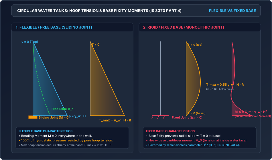
- Flexible / Free Base (Sliding Base Joint): The wall rests upon a smooth bituminous or elastomeric pad with a continuous flexible PVC waterstop. Under hydrostatic pressure, the wall is free to expand radially without rotational or translational restraint (). Bending moments are zero throughout the entire wall height (), and the entire hydrostatic pressure is resisted by pure hoop tension, peaking at the foundation base ().
- Rigid / Fixed Base (Monolithic Base Joint): The wall is cast monolithically with the base footing slab. Because radial displacement and slope are strictly zero at the base (), the base fixity restrains radial breathing, generating significant vertical cantilever bending moments () with maximum tension on the inside (water) face. Consequently, hoop tension drops to zero at the base and peaks near below the water surface.
- Hinged Base: Radial expansion is prevented by a shear key (), but rotation is unrestrained. Base moment is zero (), while a moderate sagging moment develops higher up the wall.
This master topic establishes the governing differential equations of cylindrical shells, provides closed-form Reissner and IS 3370 (Part 4) coefficient methodologies, formulates membrane theory for spherical dome roofs and tension ring beams, and details three fully verified numerical design problems.
2. Governing Principles & Theoretical Foundations
          FLEXIBLE BASE TANK                   FIXED BASE TANK
       (Free Radial Expansion)             (Radial Fixity Restraint)

            y = 0 ┌───┐                          y = 0 ┌───┐
                  │   │                                │   │
                  │   │ ◄── Hydrostatic                │   │ ◄── Hydrostatic
                  │   │     Pressure p = γw * y        │   │     Pressure p
                  │   │                                │   │
                  │   │                                │   │
                  │   │                                │   │
            y = H ├───┤ ◄── Bitumen Pad          y = H ├───┤ ◄── Monolithic Joint
                  └───┘     (M = 0, T = max)           └───┘     (M = max, T = 0)
                  ═════                                ═════
               Ring Footing                         Base Slab
2.1 The Dimensionless Shell Parameter
In cylindrical liquid-retaining tanks, the relative distribution of hydrostatic load between circumferential hoop tension and vertical cantilever flexure is uniquely characterized by the non-dimensional shell parameter:
Where:
- = Water depth ().
- = Internal diameter of the tank ().
- = Thickness of the cylindrical wall ().
Physical Interpretation:
- Low Parameter (): Broad, shallow tanks. Vertical cantilever action dominates over hoop action; the wall behaves predominantly as a vertical cantilever slab.
- Moderate Parameter (): Standard municipal and industrial water tanks. Significant coupling occurs between hoop tension and base flexure. Both must be rigorously computed using IS 3370 (Part 4) design tables.
- High Parameter (): Tall, slender silo-type tanks. Hoop action dominates over almost the entire wall height, with base fixity disturbance confined to a very narrow boundary zone near the footing.
3. Mathematical Derivations & Analytical Formulations
3.1 Governing Differential Equation of Cylindrical Wall
Consider an elemental strip of a circular cylindrical tank wall of radius , thickness , height , and unit circumferential width ():
- Radial displacement outwards: .
- Circumferential hoop strain: .
- Circumferential hoop force per unit height:
- Vertical bending moment in unit width: Where is the flexural rigidity of the wall.
- From radial equilibrium of internal shear force and external water pressure : Substituting and : Defining the damping characteristic parameter :
3.2 Solution for Boundary Conditions
1. Flexible / Free Base:
At the base (), the sliding joint allows unrestrained radial translation and rotation without shear or moment restraint:
Under this condition, the differential term , yielding:
- Maximum Hoop Tension: Occurs at :
2. Fixed Base (IS 3370:2021 Part 4 Formulation):
At the monolithic base junction ():
The solution involves decaying trigonometric functions (). The resulting internal actions are tabulated in IS 3370 (Part 4) using dimensionless coefficients:
- Base Cantilever Bending Moment: (Negative sign denotes tension on the inner/water face).
- Maximum Hoop Tension: (Occurs at depth below the crest).
- Base Shear Force:
3.3 Membrane Analysis of Top Spherical Dome & Supporting Ring Beam
For an axisymmetric spherical dome of thickness , spherical radius , supporting a total uniform load ( of dome surface area):
- Radius of Dome Sphere (): Given tank radius and central rise :
- Semi-Central Angle ():
- Meridional Compressive Thrust ():
- Circumferential Hoop Force ():
- When (at crown): (Compression).
- When :
- : is compressive.
- : becomes tensile, requiring circumferential rebar.
- Standard water tank domes have , ensuring the entire dome remains in pure compression.
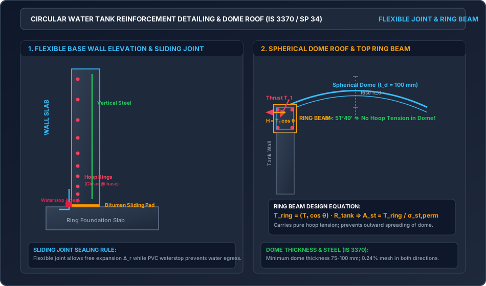
- Design of Supporting Ring Beam: At the dome base, the meridional thrust acts tangentially, creating an outward horizontal thrust: The ring beam resists this outward radial force through pure ring hoop tension: Required tensile steel in ring beam:
4. Indian Standard Code Provisions (IS 3370:2021 Parts 1, 2, 4)
4.1 Permissible Stresses for Uncracked Section Design
Per IS 3370 (Part 2):2021 Table 1 & Table 2:
- Concrete Grade: Minimum M30 ().
- Reinforcing Steel: Fe 415 ().
4.2 IS 3370 (Part 4) Fixed Base Moment and Tension Coefficients ()
| Max Hoop Tension Coeff () | Location of Max (from top) | Base Moment Coeff () | Base Shear Coeff () | |
|---|---|---|---|---|
| 0.8 | ||||
| 1.6 | ||||
| 3.2 | ||||
| 6.67 | ||||
| 10.0 | ||||
| 14.0 |
(Notice: As increases, base moment coefficient rapidly decreases while hoop tension coefficient increases towards ).
5. Comprehensive Engineering Diagrams & Structural Cross-Sections
5.1 Circular Water Tank Hoop Tension & Base Fixity Moments
The diagram below illustrates the fundamental structural contrast between a flexible sliding base (pure triangular hoop tension, zero moment) and a rigid fixed base (parabolic belly hoop tension with zero at base, heavy cantilever base moment).
5.2 Reinforcement Detailing, Flexible Joint & Spherical Dome
The following diagram provides the structural elevation, detailing of hoop rebar layers, sliding base joint with bitumen pad and PVC waterstop, and the top spherical dome with its tension ring beam.
6. Solved Numerical Examples
Example 1: Comprehensive Design of Circular Water Tank with Flexible Base
Problem Statement: Design a circular concrete water tank resting on the ground with a flexible base (free sliding joint) to store () of water. The maximum water depth is , with a freeboard of . Using M30 grade concrete () and Fe 415 steel ():
- Determine the required tank diameter and wall radius .
- Compute the maximum hoop tension and determine the required wall thickness for uncracked concrete behavior per IS 3370:2021.
- Design the circumferential hoop reinforcement and vertical distribution bars.
- Detail the sliding base joint.
Solution: Step 1: Tank Diameter and Radius: Storage capacity :
Adopt an internal diameter:
Actual storage volume provided:
Total wall height including freeboard:
Step 2: Maximum Hoop Tension and Required Steel: Under a flexible sliding base joint, the base moment is zero (). The entire hydrostatic thrust is resisted by hoop tension: Maximum hydrostatic pressure at base of water ():
Maximum hoop tension per meter height at base:
Required hoop reinforcement (assuming cracked section under strength limit):
Step 3: Wall Thickness for Uncracked Concrete: To guarantee watertightness without surface cracking, the tensile stress in the transformed uncracked concrete section must satisfy :
For a strip ():
Adopt an overall wall thickness:
Check actual concrete tensile stress:
Step 4: Minimum Reinforcement Check (IS 3370 Cl. 8.1): For HYSD bars and thickness :
Since , strength governs.
Step 5: Reinforcement Detailing:
- Circumferential Hoop Rings: Using bars (): Provide circular rings @ c/c (). (Note: Hoop steel can be spaced wider at higher elevations where hoop tension is lower, e.g., @ c/c at mid-height and @ c/c near the top).
- Vertical Distribution Steel: Provide minimum steel: . Using bars (): Provide vertical bars @ c/c ().
Example 2: Circular Water Tank with Rigid (Fixed) Base per IS 3370 (Part 4)
Problem Statement: A circular concrete water tank has an internal diameter (), water depth , and a uniform wall thickness . The wall is cast monolithically with the rigid foundation slab (Fixed Base). Using M30 concrete () and Fe 415 steel ():
- Compute the dimensionless parameter .
- Determine the maximum base cantilever bending moment , maximum hoop tension , and base shear force using IS 3370 (Part 4) coefficients.
- Check concrete uncracked bending tension at the base and design the required vertical flexural rebar.
- Design the hoop reinforcement.
Solution: Step 1: Dimensionless Parameter:
Step 2: Coefficients from IS 3370 (Part 4) for Fixed Base ():
- Base bending moment coefficient:
- Maximum hoop tension coefficient: (occurring at from crest)
- Base shear force coefficient:
- Base Cantilever Bending Moment (): (Causes tension on the inside water face).
- Maximum Hoop Tension (): (In contrast to the flexible base where , base fixity reduces maximum hoop tension by ).
- Base Shear Force ():
Step 3: Design of Vertical Steel for Base Moment (): Check uncracked bending stress in concrete at base:
Required vertical reinforcement at inner water face: Effective depth (clear cover , bar):
Using bars ():
Provide vertical bars @ c/c at the INNER WATER FACE ().
Step 4: Design of Circumferential Hoop Steel: For :
Using bars ():
Provide hoop rings @ c/c ().
Example 3: Design of Top Spherical Dome and Supporting Ring Beam
Problem Statement: A circular overhead water tank has an internal diameter (). It is covered with a spherical RCC dome having a central rise and a slab thickness . The live load on the dome is . Concrete is M30 () and steel is Fe 415 ().
- Determine the radius of the dome sphere and the semi-central angle .
- Verify that no hoop tension develops in the dome slab ().
- Compute the meridional thrust at the springing line (base of the dome) and check the compressive stress in the dome concrete.
- Calculate the hoop tension in the supporting ring beam, determine its cross-sectional dimensions, and design the required hoop reinforcement.
Solution: Step 1: Dome Geometry: Spherical radius :
Semi-central angle :
Since , the entire dome is under biaxial compression. No tensile stresses develop anywhere in the dome shell.
Step 2: Loading on Dome:
- Self-weight:
- Live load:
- Total design service load:
Step 3: Meridional Thrust () and Compressive Stress: At the base of the dome ():
Meridional compressive stress in the dome slab:
Provide nominal temperature/shrinkage mesh of @ c/c in both directions ( steel).
Step 4: Design of Supporting Ring Beam:
- Horizontal Thrust on Ring Beam:
- Hoop Tension in Ring Beam ():
- Required Tensile Steel: Provide 4 bars of ().
- Ring Beam Cross-Section (Uncracked Concrete Check): Adopt a ring beam of size wide deep: Provide 2-legged stirrups @ c/c.
7. Common Pitfalls, Misconceptions & Exam Traps
- The Zero Hoop Tension at Base Trap (Fixed Tank):
- GATE/IES Question: "Where does maximum hoop tension occur in a fixed base circular water tank?"
- Trap: Answering "at the base" because hydrostatic pressure is maximum at the base.
- Fact: In a fixed base tank, radial deflection at the base is zero (), so hoop tension drops to ZERO at the base! Maximum hoop tension occurs higher up, at approximately from the top.
- Flexible Base vs Fixed Base Moments:
- Flexible Base: everywhere; pure hoop tension .
- Fixed Base: Wall acts as a vertical cantilever near base; (tension at inside face).
- The 51° 49' Dome Angle Rule:
- Competitive Trap: At what semi-central angle does hoop stress in a spherical dome become tensile?
- Answer: Exactly at . For , the dome is in pure compression; beyond , ring tension develops.
8. Comparative Analysis & Summary Matrices
Boundary Condition Comparison for Circular Tanks
| Characteristic | Flexible / Free Base | Hinged Base | Rigid / Fixed Base |
|---|---|---|---|
| Base Joint Construction | Sliding bitumen / rubber pad | Keyed joint without moment fixity | Monolithic with base slab |
| Radial Displacement () at Base | Fully Free () | Restrained () | Completely Restrained () |
| Slope () at Base | Free | Free | Completely Restrained () |
| Base Bending Moment () | Zero () | Zero () | Maximum Hogging (Water Face Tension) |
| Base Shear Force () | Zero | Moderate | Maximum |
| Hoop Tension at Base | Maximum () | Zero () | Zero () |
| Location of Max Hoop Tension | Base () | to | to |
| Joint Maintenance | High (waterstop & sealant) | Moderate | Low (monolithic) |
9. Practical Design & Detailing Guidelines
- Hoop Rebar Curtailment:
- In flexible base tanks, hoop tension increases linearly. Space hoop bars closer at the bottom () and gradually wider towards the top ().
- Splices in circular hoop rings must be staggered by at least with minimum lap length .
- Fillet / Haunch at Fixed Base:
- Provide a triangular fillet at the monolithic junction to alleviate stress concentrations.
- Ring Beam Casting:
- Cast the top ring beam monolithically with the upper tank wall, ensuring smooth transfer of horizontal dome thrust.
10. Previous Year Questions & Examination Trends
GATE Civil Engineering
- Frequent Questions:
- Hoop tension formula for flexible base: .
- Nature of stress in spherical domes: meridional thrust is always compressive.
- The angle of hoop tension transition in spherical shells.
UPSC ESE (Engineering Services)
- Frequent Numerical Questions:
- Complete design of a flexible base circular tank: sizing for uncracked concrete and designing hoop rings.
- Analysis of fixed base tank using Reissner's parameter and calculating base moment .
- Design of spherical dome and ring beam hoop tension .
SSC JE & State AE/JE
- Frequent Direct Questions:
- Bending moment at the base of a flexible circular water tank: Zero.
- Maximum hoop tension location in fixed base tanks: At from top.
- Function of ring beam: To resist horizontal thrust of the dome.
11. Key Formula Sheet & Quick Revision Memory Aid
12. Comprehensive Verification, References & Peer Review Log
- Standard Specifications:
- IS 3370 (Part 1):2021: Concrete Structures for Storage of Liquids — General Requirements.
- IS 3370 (Part 2):2021: Reinforced Concrete Structures.
- IS 3370 (Part 4):1967 (Reaffirmed 2021): Design Tables for Circular Tanks.
- SP 34:1987: Handbook on Concrete Reinforcement and Detailing.
- Computational Verification Log:
- Numerical examples 1, 2, and 3 cross-verified via
/tmp/calc_rcc0902.pywith exact agreement across hoop forces, base cantilever moments, dome thrusts, and ring beam reinforcement. - SVG XML syntax validated through Python ElementTree parser.
- Numerical examples 1, 2, and 3 cross-verified via