Rectangular Water Tanks (Overhead & Underground Systems, Joint Details)
In this chapter (3 topics)
On this page
- 1. Introduction & Structural System Overview
- 2. Structural Classification & Load Transfer Mechanics
- 2.1 Case 1: Approximate Square or Box Tanks (L/B < 2)
- 2.2 Case 2: Long Rectangular Tanks (L/B ≥ 2)
- 3. Elastic Frame Analysis for L/B < 2 (Moment Distribution & Axial Tension)
- 3.1 Closed Frame Moment Distribution Derivation
- 3.2 Direct Axial Tension in Walls
- 3.3 Corner Splays / Haunches
- 4. Cross-Sectional Design under Combined Flexure and Tension (IS 3370:2021)
- 4.1 Effective Design Moment (Meff)
- 4.2 Required Tensile Reinforcement (Ast)
- 4.3 Uncracked Concrete Stress Verification (Resistance to Cracking)
- 5. Underground Water Tanks: Load Combinations & Geotechnical Mechanics
- 5.1 Governing Design Combinations
- 5.2 Lateral Inward Pressure on Underground Walls
- 5.3 Anti-Flotation Factor of Safety (FSuplift)
- 5.4 Net Upward Pressure on Base Slab
- 6. Worked Numerical Examples with Complete Step-by-Step Verification
- Problem 1: Design of Overhead Rectangular Tank Walls (L/B < 2)
- Problem 2: Design of Long Rectangular Tank (L/B ≥ 2) Long Wall Cantilever
- Problem 3: Underground Tank Flotation Stability & Uplift Verification
- 7. Comparative Technical Matrix: Circular vs Rectangular Tanks
- 8. Construction Practices & Site Pitfalls
- 9. Competitive Examination Traps & Problem-Solving Shortcuts
- 10. Practice Problems & Examination Review Exercises
- Level 1: Objective Conceptual (SSC JE / RRB JE)
- Level 2: Multi-Concept Analytical (GATE CE)
- Level 3: Conventional Design Problem (UPSC ESE Mains)
- 11. Complete Topic Architecture & Upstream/Downstream Dependencies
- 12. Verification & Standards References
1. Introduction & Structural System Overview
Rectangular water tanks represent the most spatially versatile class of liquid-retaining structures in municipal water distribution, industrial processing plants, and residential townships. While circular tanks develop optimal structural efficiency through membrane hoop tension, rectangular configurations are often preferred where site boundaries, spatial constraints, or multi-compartment process layouts preclude circular geometry.
                      RECTANGULAR WATER TANK TAXONOMY
                                     │
         ┌───────────────────────────┴───────────────────────────┐
         ▼                                                       ▼
   Overhead / Ground Tanks                               Underground Tanks
   (Subjected to internal water                          (Subjected to external soil/water
    pressure and wind/seismic)                            uplift and empty/full load cases)
         │                                                       │
         ├───────────────────────────┐                           ├───────────────────────────┐
         ▼                           ▼                           ▼                           ▼
   Aspect Ratio L/B < 2        Aspect Ratio L/B ≥ 2        Tank Empty Case             Tank Full Case
   (Closed Horizontal Frame)   (Cantilever Long Walls      (Maximum Inward Surcharge   (Internal Hydrostatic;
                                + Spanning Short Walls)     & Flotation Uplift Head)    Zero Earth Resistance)
The structural response of a rectangular liquid container is governed fundamentally by its plan aspect ratio (ratio of long dimension to short dimension ) and wall height-to-span ratio . Unlike circular tanks where wall deflection is axisymmetrical, the orthogonal intersections of rectangular walls generate complex three-dimensional plate bending, corner stress concentrations, and combined direct tension and flexure across multiple planes.
2. Structural Classification & Load Transfer Mechanics
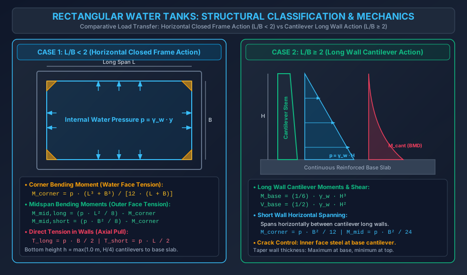
The distribution of internal hydrostatic pressure between horizontal bending (ring/frame action) and vertical bending (cantilever action) depends strictly on aspect ratio:
2.1 Case 1: Approximate Square or Box Tanks ()
When the length is less than twice the breadth (), the walls cannot act independently as simple cantilevers. Instead, the walls interact at every horizontal cross-section as a continuous closed rectangular frame:
- Upper Portion (): The upper wall zone transfers hydrostatic pressure primarily by horizontal frame action, where the walls bend horizontally while carrying simultaneous direct tension pulled by adjacent walls.
- Lower Base Portion (): Due to monolithic fixity with the base slab, the bottom portion transfers pressure directly to the foundation through vertical cantilever action.
2.2 Case 2: Long Rectangular Tanks ()
When , the central regions of the long walls are too distant from the corners to benefit from frame continuity:
- Long Walls: Act primarily as vertical cantilevers fixed at the base slab. Hydrostatic pressure produces triangular bending moments with maximum tension on the inner (water-contact) face at the base:
- Short Walls: Span horizontally between the rigid long walls, supported at their vertical edges. In addition to horizontal bending, the short walls carry axial tension transferred from the long wall water thrust.
3. Elastic Frame Analysis for (Moment Distribution & Axial Tension)
Consider a horizontal slice of unit height () at a depth below the free water surface, subjected to uniform internal hydrostatic burst pressure .
3.1 Closed Frame Moment Distribution Derivation
By slope-deflection or moment distribution on a closed symmetric rectangular ring of dimensions :
-
Fixed End Moments:
-
Corner Joint Bending Moment (): Assuming uniform wall thickness (, equal flexural stiffness ):
Substituting into slope-deflection equations yields the corner moment:
For a perfectly square tank ():
Nature of Stresses: At the corners, outward pressure produces convex inward curvature, causing tension on the inside water face and compression on the outside face.
-
Midspan Bending Moments: By statics, the free bending moment of a simply supported span is . The net midspan moment is obtained by subtracting the corner restraint moment:
- Long Wall Midspan Moment:
- Short Wall Midspan Moment:
For a square tank ():
Nature of Stresses: At midspan, positive bending causes tension on the outside (remote) face and compression on the inside water face.
3.2 Direct Axial Tension in Walls
Because the walls form a closed equilibrium envelope, each wall acts as an end support for the orthogonal wall, sustaining direct tensile pull:
- Direct Tension in Long Wall:
- Direct Tension in Short Wall:
3.3 Corner Splays / Haunches
To alleviate extreme stress concentrations at orthogonal re-entrant corners and prevent early water leakage, IS 3370 strongly recommends providing diagonal concrete haunches (splays), typically or , reinforced with diagonal corner ties.
4. Cross-Sectional Design under Combined Flexure and Tension (IS 3370:2021)
Every wall element is subjected simultaneously to a bending moment and an axial tension .
4.1 Effective Design Moment ()
To design the tension reinforcement, the axial tensile force is shifted to the centroid of the tensile reinforcement:
where is the eccentricity of the tension steel with respect to the mid-depth axis of the wall ().
4.2 Required Tensile Reinforcement ()
Using the Working Stress Method (WSM) per IS 3370:
where:
- (for Fe 415 in liquid-retaining faces per IS 3370:2021)
4.3 Uncracked Concrete Stress Verification (Resistance to Cracking)
To prevent leakage under working service loads, the combined tensile stresses on the transformed uncracked section must satisfy:
where:
For M30 concrete: and .
5. Underground Water Tanks: Load Combinations & Geotechnical Mechanics
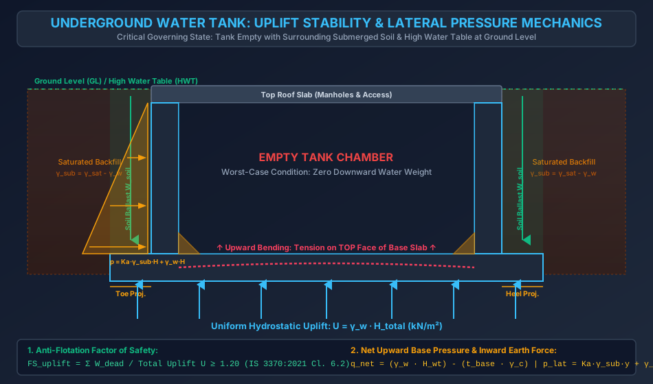
Underground water tanks are subject to external soil and groundwater pressures that reverse the internal stress patterns:
5.1 Governing Design Combinations
Per IS 3370 (Part 1 & 2):2021, underground tanks must be verified under two extreme, non-concurrent limit states:
| Combination | Operational Status | External Conditions | Critical Stresses & Structural Action |
|---|---|---|---|
| Case 1 | Tank Empty | Submerged backfill, high water table at GL | Maximum flotation uplift, inward lateral earth/water pressure, tension on top face of base slab, outer face wall tension. |
| Case 2 | Tank Full | No external earth backfill (testing/excavation) | Maximum outward hydrostatic burst pressure, tension on inside water face, maximum corner moments. |
5.2 Lateral Inward Pressure on Underground Walls
When the water table rises to ground level, the soil is completely submerged:
where:
- (Rankine's active earth pressure coefficient)
- (submerged effective unit weight of backfill)
- (unit weight of water)
5.3 Anti-Flotation Factor of Safety ()
When the tank is empty, the entire displaced groundwater volume exerts an upward buoyant force (Archimedes' thrust) on the tank footprint:
To ensure global equilibrium against flotation, a base slab projection (heel/toe) is cast projecting outward by to all around the tank perimeter. This projection engages the downward gravity ballast of the overlying soil column:
Mandatory Rule: IS 3370:2021 explicitly mandates . If , the base slab projection width must be increased, or a heavier raft foundation provided.
5.4 Net Upward Pressure on Base Slab
In the empty condition, the base slab behaves as a continuous inverted raft spanning between the perimeter and partition walls:
This uniform upward pressure causes hogging curvature between walls, placing the TOP face of the base slab into tension.
6. Worked Numerical Examples with Complete Step-by-Step Verification
Problem 1: Design of Overhead Rectangular Tank Walls ()
Statement:
A rectangular water tank resting on columns has internal plan dimensions of and , with a water depth of . Using M30 concrete and Fe 415 steel, analyze the horizontal closed frame at a depth of below the water surface (assuming bottom cantilevers to base slab). Calculate corner and midspan bending moments, direct tensions, required reinforcement, and verify uncracked concrete stresses with a corner haunch.
Solution:
Step 1: Hydrostatic Pressure at Frame Depth:
- Cantilever bottom zone: .
- Design depth for horizontal frame action: .
- Hydrostatic burst pressure:
Step 2: Corner and Midspan Bending Moments:
- Corner bending moment (tension on inner water face):
- Midspan bending moments (tension on outer face): (Note: The negative sign indicates that for this aspect ratio, the short wall midspan remains slightly in hogging/corner-type curvature, requiring continuous inner reinforcement).
Step 3: Direct Axial Tensions:
- Direct tension in long wall:
- Direct tension in short wall:
Step 4: Design of Tension Steel at Corner (Inner Face):
- Adopt wall thickness with corner haunch.
- Clear cover , bar diameter .
- Centroid distance: .
- Design moment:
- For M30 () and Fe 415 ():
- Steel area required:
- Provide bars @ c/c () or bars @ c/c ().
Step 5: Uncracked Concrete Tensile Stress Verification:
- At corner with haunch, effective thickness along diagonal .
- Transformed uncracked area:
- Uncracked section modulus:
- Direct tensile stress:
- Bending tensile stress:
- Combined interaction check:
Problem 2: Design of Long Rectangular Tank () Long Wall Cantilever
Statement:
A ground-supported rectangular water tank has plan dimensions and () and a total height . Design the long wall as a vertical cantilever fixed to the base slab using M30 concrete and Fe 415 steel. Determine the required base thickness for uncracked tensile performance, base bending moment, and vertical steel.
Solution:
Step 1: Boundary Classification & Load Action:
- Aspect ratio: .
- Hence, the long wall behaves as a pure vertical cantilever fixed to the base slab.
- Hydrostatic pressure distribution: , peaking at base .
Step 2: Base Cantilever Moments & Shear:
- Base bending moment (inner water face tension):
- Base shear force:
Step 3: Minimum Uncracked Wall Thickness at Base:
- For an uncracked section under pure bending tension:
- Adopt tapered wall: at bottom, tapering linearly to at crest.
Step 4: Design of Main Vertical Reinforcement (Inner Face):
- Effective depth at base: .
- With and :
- Provide bars @ c/c ().
- Check actual uncracked stress:
Problem 3: Underground Tank Flotation Stability & Uplift Verification
Statement:
An underground rectangular water tank has external dimensions of and total depth of . The groundwater table reaches ground level. Soil properties: . Tank construction: roof slab thick, walls thick, base slab thick with an outward projection of all around. Concrete density .
Verify the factor of safety against flotation when the tank is empty, and calculate the net upward bending moment on the base slab.
Solution:
Step 1: Geometry & Footprint Dimensions:
- Tank external size: ().
- Base projection: all around.
- Base slab total dimensions:
- Base projection area: .
Step 2: Total Upward Flotation Thrust (Uplift Force):
- Total depth from ground level to bottom of base slab:
- Total buoyant uplift force:
Step 3: Downward Gravity Dead Weight (Tank Empty):
- Roof Slab Weight:
- Base Slab Weight:
- Wall Weight:
- Mean wall perimeter: .
- Soil Ballast Weight over Projection:
- Total Dead Weight:
Step 4: Factor of Safety against Flotation:
Step 5: Net Upward Pressure & Bending Moments on Base Slab:
- Upward water pressure at underside: .
- Downward dead weight of base slab: .
- Net upward pressure acting inside the tank chamber:
- Clear internal span between long walls: .
- Considering full monolithic fixity at wall supports:
- Support Moment (Under Wall Base):
- Midspan Moment (Center of Chamber):
7. Comparative Technical Matrix: Circular vs Rectangular Tanks
| Design Parameter | Circular Tanks () | Rectangular Tanks () | Rectangular Tanks () |
|---|---|---|---|
| Primary Structural Action | Pure membrane ring hoop tension | Closed 2D horizontal frame action | Long walls: Cantilever; Short walls: Spanning |
| Bending Moments | Zero (flexible base) or localized at base (fixed) | High at corners () and midspan | Maximum base cantilever moment () |
| Critical Tension Face | Hoop hoop tension across entire thickness | Inner face at corners; Outer face at midspan | Inner face at base of long wall |
| Corner Discontinuity | None (continuous circular symmetry) | Severe stress concentration; requires haunch | Severe orthogonal intersection stress |
| Material Efficiency | Highest (minimal concrete & steel) | Moderate (governed by flexure) | Lowest (heavy cantilever wall sections) |
| Formwork & Construction | Curved shutters; specialized staging | Simple straight formwork; easy fabrication | Simple straight formwork; easy fabrication |
| Spatial Footprint | Low area utilization in rectangular plots | High area utilization; easy partitioning | Excellent for long narrow industrial channels |
8. Construction Practices & Site Pitfalls
-
Omission of Corner Splays (Haunches): Site Failure: Casting sharp corners without diagonal splays leads to early thermal contraction and flexural cracking along the re-entrant line. Standard Practice: Cast or splays at all vertical wall junctions with diagonal corner hairpins.
-
Incorrect Rebar Placement in Underground Base Slabs: Site Error: Placing heavy reinforcement only at the bottom face of an underground tank base slab (confusing it with building footings). Consequence: Under high groundwater uplift during tank dewatering or construction, the slab experiences hogging tension on its top face, causing rupture and rapid flooding of the tank. Remedy: Place main flexural steel in the TOP face of the base slab to resist .
-
Inadequate Projection for Uplift Ballast: Failure Mechanism: Truncating base slab projections flush with exterior walls to save excavation cost causes global flotation of the empty tank during monsoons, shearing inlet/outlet pipes. Remedy: Always provide continuous base projections () verified for under saturated soil weight.
-
Construction Joint Sealing: Pitfall: Incomplete compaction around PVC central-bulb waterstops at the wall-base junction (the kicker joint). Remedy: Use hydrophilic expanding swelling strips or serrated PVC waterstops, fully vibrated with poker needles diameter around rebar cages.
9. Competitive Examination Traps & Problem-Solving Shortcuts
-
Corner Moment vs Midspan Moment Trap (GATE/ESE):
- Question asks: "In a square water tank of side subjected to water pressure , the ratio of corner bending moment to midspan bending moment is:"
- Corner moment: (tension inside).
- Midspan moment: (tension outside).
- Ratio: ! The corner moment is exactly twice the midspan moment.
-
Direct Tension Magnitude Trap (SSC JE/RRB JE):
- Tension in the long wall is governed by the thrust on the short wall: .
- Tension in the short wall is governed by the thrust on the long wall: .
- Trap: Students routinely calculate , which is disastrously wrong.
-
Flotation Safety Factor Limit (IS 3370:2021 vs IS 456:2000):
- In general building foundations (IS 456 Cl. 20.2), stability against uplift requires (or with DL only).
- In liquid retaining structures (IS 3370 Cl. 6.2), the mandatory factor of safety against flotation is strictly .
10. Practice Problems & Examination Review Exercises
Level 1: Objective Conceptual (SSC JE / RRB JE)
-
In a rectangular water tank with , the walls primarily resist hydrostatic pressure through:
- (A) Vertical cantilever action
- (B) Horizontal closed frame action
- (C) Pure membrane hoop action
- (D) Arch action
Answer: (B)
-
At the re-entrant corners of a rectangular water tank, tension due to internal water pressure develops at:
- (A) Outside face of the wall
- (B) Inside (water-contact) face of the wall
- (C) Mid-depth of the wall
- (D) Diagonal neutral axis
Answer: (B)
-
For an underground water tank, the most critical condition for flotation occurs when:
- (A) Tank is full with groundwater table at base
- (B) Tank is empty with groundwater table at ground surface
- (C) Tank is half-full with dry backfill
- (D) Tank is full during maximum rainfall
Answer: (B)
Level 2: Multi-Concept Analytical (GATE CE)
- A square water tank of side length is designed as a continuous horizontal frame at depth . Taking , the corner moment and midspan moment are respectively:
- (A) and
- (B) and
- (C) and
- (D) and
Solution: . . . Correct choice is (A).
Level 3: Conventional Design Problem (UPSC ESE Mains)
- A rectangular underground tank of internal plan dimensions and height is founded in submerged soil () with water table at ground level. (a) Proportion a perimeter base slab projection to provide when empty (). (b) Draw the lateral earth and water pressure diagram on the wall for the empty condition. (c) Detail the reinforcement required in the base slab indicating top vs bottom face steel.
11. Complete Topic Architecture & Upstream/Downstream Dependencies
                       REINFORCED CONCRETE STRUCTURES
                                     │
           ┌─────────────────────────┴─────────────────────────┐
           ▼                                                   ▼
Chapter 08: Retaining Walls                         Chapter 09: Water Tanks
(Earth pressure, Cantilever &                       (IS 3370:2021 Limit States)
 Counterfort Walls)                                             │
                                     ┌─────────────────────────┴─────────────────────────┐
                                     ▼                                                   ▼
                             Topic 09-02: Circular Tanks                         Topic 09-03: Rectangular Tanks
                             (Hoop tension, Base fixity,                         (Frame action, Cantilever long walls,
                              Spherical Domes & Ring Beams)                       Underground Flotation & Uplift)
                                                                                         │
                                                                                         ▼
                                                                                 Chapter 10: Prestressed Concrete
                                                                                 (IS 1343:2012 Systems & Losses)
- Upstream Dependencies:
RCC-09-01: Working stress uncracked design formulas (), Tightness Classes 1 & 2 crack widths, and joint configurations.RCC-08-01: Rankine earth pressure formulations () and submerged soil unit weights.
- Downstream Dependencies:
RCC-10-01toRCC-10-04: Prestressed concrete tanks and pressure pipes (IS 1343 & IS 784), circular prestressing with wire winding machines.
12. Verification & Standards References
- Bureau of Indian Standards:
- IS 3370 (Part 1): 2021 – Code of Practice for Concrete Structures for the Storage of Liquids: General Requirements.
- IS 3370 (Part 2): 2021 – Code of Practice for Concrete Structures for the Storage of Liquids: Reinforced Concrete Structures.
- IS 3370 (Part 4): 1967 (Reaffirmed 2018) – Design Tables for Thin Cylindrical and Rectangular Tanks.
- IS 456: 2000 (Reaffirmed 2021) – Plain and Reinforced Concrete - Code of Practice (Clauses 20.2, 34, and Annex B).
- Core Textbooks & Reference Manuals:
- Krishna Raju, N., Advanced Reinforced Concrete Design (IS 456 & IS 3370), CBS Publishers.
- Punmia, B.C., Jain, A.K., and Jain, A.K., Reinforced Concrete Structures (Vol. II), Laxmi Publications.
- Dayaratnam, P., Design of Reinforced Concrete Structures, Oxford & IBH.