Water Tank Design Principles & Limit States of Cracking (IS 3370:2021)
In this chapter (3 topics)
On this page
- 1. Executive Summary & Overview
- 2. Governing Principles & Theoretical Foundations
- 2.1 Environmental Exposure and Cover Requirements
- 3. Mathematical Derivations & Analytical Formulations
- 3.1 Design of Sections without Cracking (Uncracked Concrete Method)
- 3.2 Limit State Method Crack Width Formulation (IS 3370:2021 Annex B)
- 4. Indian Standard Code Provisions (IS 3370:2021 Parts 1 & 2)
- 4.1 Permissible Stresses in Concrete (Uncracked Working Stress Check)
- 4.2 Permissible Stresses in Steel Reinforcement
- 4.3 Minimum Reinforcement Rules (Clause 8.1)
- 5. Comprehensive Engineering Diagrams & Structural Cross-Sections
- 5.1 IS 3370 Water Tank Cracking Limit States & Stress Profiles
- 5.2 Water Tank Movement Joints & Waterstop Detailing
- 6. Solved Numerical Examples
- Example 1: Design of Circular Tank Wall under Pure Hoop Tension (Uncracked Limit State)
- Example 2: Combined Axial Tension and Bending Moment Verification
- Example 3: Limit State Method Crack Width Verification (Tightness Class 1)
- 7. Common Pitfalls, Misconceptions & Exam Traps
- 8. Comparative Analysis & Summary Matrices
- Tightness Classification per IS 3370:2021
- 9. Practical Design & Detailing Guidelines
- 10. Previous Year Questions & Examination Trends
- GATE Civil Engineering
- UPSC ESE (Engineering Services)
- SSC JE & State AE/JE
- 11. Key Formula Sheet & Quick Revision Memory Aid
- 12. Comprehensive Verification, References & Peer Review Log
1. Executive Summary & Overview
Liquid-retaining structures, commonly designated as water tanks, represent specialized reinforced concrete systems engineered to store water, sewage, industrial effluents, and other aqueous fluids without leakage, percolation, or structural distress. Unlike conventional building structures where design is primarily governed by the limit state of collapse (ultimate strength) and normal serviceability deflection limits, liquid-retaining structures are strictly governed by serviceability criteria of watertightness and crack width limitation.
The Indian Standard code governing these structures, IS 3370 ("Code of Practice for Concrete Structures for the Storage of Liquids"), underwent a monumental conceptual transition from its classical 1965 Working Stress formulation to the modernized Limit State methodology codified in IS 3370:2009 and reaffirmed/refined in IS 3370:2021:
- Evolution from WSM to LSM:
- In the 1965 edition, water tightness was achieved exclusively through the Working Stress Method (WSM) by keeping direct and bending tensile stresses in the concrete below permissible uncracked tensile limits ( and ), while restricting steel stresses to low values ().
- In IS 3370:2021, the Limit State Method (LSM) is established as the primary design foundation, requiring rigorous dual-stage verification:
- Limit State of Serviceability (Cracking): Evaluated under unfactored service loads (), ensuring that calculated surface crack widths do not exceed strictly specified limits ( for Tightness Class 1, for Tightness Class 2, or zero cracking for Class 3).
- Limit State of Collapse (Strength): Evaluated under factored design loads () per IS 456:2000, ensuring complete structural safety against ultimate rupture and shear failure.
- Tightness Classification System:
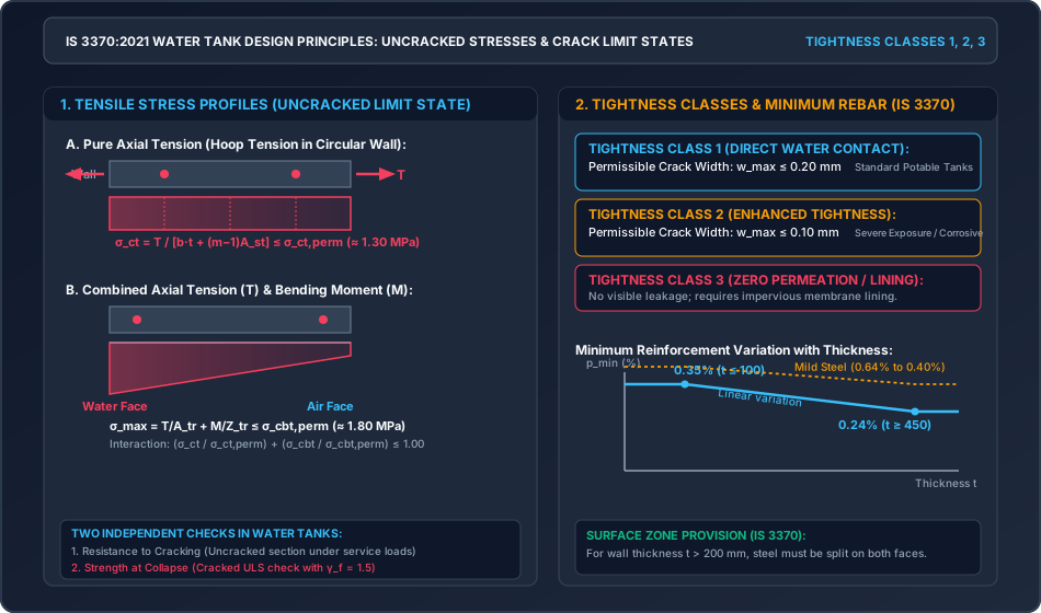
- Class 1: Direct water contact where minor surface dampness is acceptable but visible running leaks are prohibited ().
- Class 2: Severe exposure or underground tanks where damp patches must be strictly avoided ().
- Class 3: Zero leakage / chemical storage, requiring impermeable elastomeric or metallic membrane linings.
This master topic establishes the theoretical principles governing uncracked and cracked section mechanics, derives the mathematical formulations for direct tension, bending tension, and combined interaction, details the IS 3370:2021 crack width calculation equations, and provides three pre-calculated numerical problems.
2. Governing Principles & Theoretical Foundations
               ◄────────────── Thickness t ──────────────►
               ┌─────────────────────────────────────────┐
               │  o           o           o           o  │ ◄── Water Face Reinforcement
   WATER       │                                         │
   SIDE        │                                         │
               │                                         │
               │  o           o           o           o  │ ◄── Air Face Reinforcement
               └─────────────────────────────────────────┘
               ◄── Cover ──►                             ◄── Cover ──►
2.1 Environmental Exposure and Cover Requirements
Per IS 3370 (Part 1):2021 Clause 7.2:
- Liquid retaining structures are categorized under Severe or Very Severe environmental exposure categories per Table 3 of IS 456:2000.
- Minimum Nominal Concrete Cover:
- Water face: Minimum (can be reduced to for M30 and above, but is standard practice).
- Soil face (in underground tanks): Minimum (or if cast directly against unformed ground).
- External air face: Minimum .
- Minimum Concrete Grade:
- Reinforced concrete liquid retaining structures: M30 minimum (M25 was permitted in earlier codes, but M30 is mandatory under IS 3370:2021 for durability and low permeability).
- Prestressed concrete liquid retaining structures: M40 minimum.
- Maximum Water-Cement Ratio: (strictly enforced to eliminate capillary porosity).
- Minimum Cementitious Content: to .
3. Mathematical Derivations & Analytical Formulations
3.1 Design of Sections without Cracking (Uncracked Concrete Method)
When water tightness is achieved by preventing macro-cracking, the concrete is assumed to take tension up to its permissible tensile strength.
1. Pure Axial (Direct) Tension ():
Consider a unit length () of a circular tank wall of thickness , subjected to hoop tension :
- Transformed Uncracked Area (): Where is the modular ratio (per IS 456 Annex B).
- Tensile Stress in Concrete ():
- Required Minimum Wall Thickness ():
- Steel Stress at Ultimate / Cracked Condition: In the event that the concrete cracks, the reinforcement alone must sustain the full tensile force:
2. Pure Bending Moment ():
Consider a slab section subjected to bending moment :
- Transformed Moment of Inertia (): For a symmetrically reinforced section ( on both faces at distance from mid-depth):
- Transformed Section Modulus ():
- Tensile Stress in Concrete Due to Bending ():
3. Combined Axial Tension () and Bending ():
When the section is subjected simultaneously to direct tension and bending moment :
- Total Surface Tensile Stress:
- IS 3370 Interaction Criterion:
3.2 Limit State Method Crack Width Formulation (IS 3370:2021 Annex B)
Under the Limit State Method, the section is assumed to crack, but the design surface crack width under service loads must not exceed (Class 1) or (Class 2).
Governing Crack Width Formula:
Where:
- = Distance from the point on the surface where crack width is calculated to the surface of the nearest longitudinal bar:
- = Center-to-center spacing of longitudinal bars.
- = Minimum clear cover to the rebar.
- = Overall thickness of the member ().
- = Depth of the cracked neutral axis.
- = Average strain at the level considered, accounting for tension stiffening:
Where:
- is the strain at the tensile surface neglecting concrete tension.
- = Service tensile stress in the reinforcement calculated on the cracked transformed section.
4. Indian Standard Code Provisions (IS 3370:2021 Parts 1 & 2)
4.1 Permissible Stresses in Concrete (Uncracked Working Stress Check)
Per IS 3370 (Part 2):2021 Table 1:
| Concrete Grade | Permissible Direct Tension (, ) | Permissible Bending Tension (, ) | Permissible Direct Compression (, ) | Permissible Bending Compression (, ) | Modular Ratio () |
|---|---|---|---|---|---|
| M25 | |||||
| M30 | |||||
| M35 | |||||
| M40 |
(Note: In IS 456:2000, concrete tensile strength is completely neglected in flexure. In IS 3370, uncracked tensile capacity is explicitly utilized to safeguard watertightness).
4.2 Permissible Stresses in Steel Reinforcement
Per IS 3370 (Part 2):2021 Table 2:
- For High Yield Strength Deformed (HYSD) bars (Fe 415):
- In direct tension and bending tension within of liquid face: .
- In members thick, on the face remote from liquid: (or for Fe 500).
- In compression: (Fe 415).
4.3 Minimum Reinforcement Rules (Clause 8.1)
To control shrinkage and thermal strains:
- HYSD Bars (Fe 415 / Fe 500):
- For thickness : .
- For thickness : .
- For , interpolate linearly:
- Mild Steel (Fe 250):
- for , decreasing to for .
- Distribution on Faces (Surface Zone Rule):
- For walls or slabs having thickness , reinforcement must be split into two distinct layers placed near each surface.
- For liquid-contact faces, the steel in each face shall not be less than two-thirds of the minimum required reinforcement.
5. Comprehensive Engineering Diagrams & Structural Cross-Sections
5.1 IS 3370 Water Tank Cracking Limit States & Stress Profiles
The diagram below illustrates the uncracked stress profiles under pure axial tension and combined tension-bending, the Tightness Classification criteria, and the linear variation of minimum steel percentage.
5.2 Water Tank Movement Joints & Waterstop Detailing
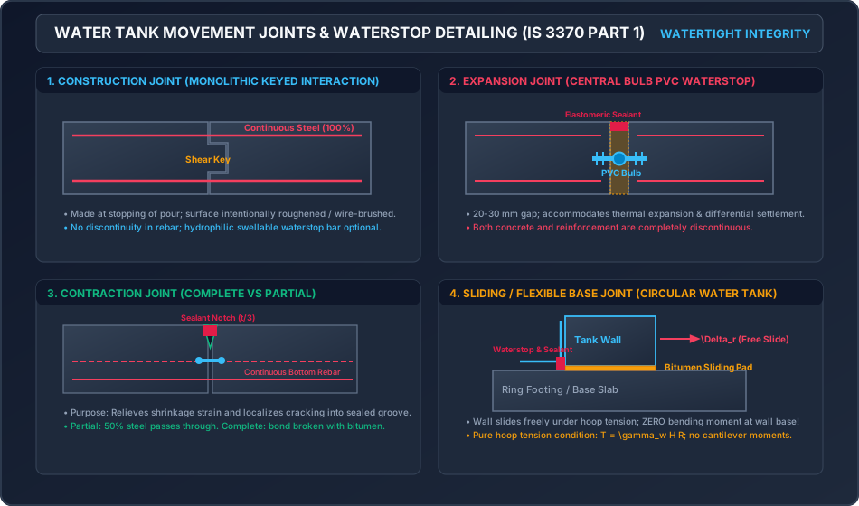
The following diagram provides engineering details of the four essential joint types codified in IS 3370 Part 1: Construction Joints, Complete/Partial Contraction Joints, Expansion Joints with central-bulb PVC waterstops, and Sliding/Flexible Base Joints.
6. Solved Numerical Examples
Example 1: Design of Circular Tank Wall under Pure Hoop Tension (Uncracked Limit State)
Problem Statement: A cylindrical concrete water tank has an internal diameter and water depth . At a height above the base, the circular wall is subjected to a service hoop tension . Design the wall thickness and hoop reinforcement using M30 grade concrete and Fe 415 steel to satisfy the uncracked water tightness condition of IS 3370:2021.
Solution: Step 1: Material Design Constants per IS 3370:
- For M30 concrete:
- For Fe 415 steel:
Step 2: Reinforcement Area Based on Strength (): Assuming concrete cracks at ultimate limit, the steel alone carries the entire hoop tension:
Step 3: Concrete Thickness () Based on Uncracked Condition: To ensure no cracking, the actual tensile stress in concrete must not exceed :
For a strip ():
Adopt an overall wall thickness:
Step 4: Check Actual Concrete Tensile Stress:
Step 5: Minimum Reinforcement Check (IS 3370 Cl. 8.1): For HYSD bars and :
Since , minimum steel is satisfied.
Step 6: Provide Reinforcement: Using bars ():
Provide circular hoop rings @ c/c (). Because thickness , rings may be placed in a single central layer with clear cover .
Example 2: Combined Axial Tension and Bending Moment Verification
Problem Statement: A rectangular water tank wall has a thickness . At a critical section, it is subjected to a service axial tension and a simultaneous service bending moment . The wall is reinforced symmetrically on both faces with bars @ c/c (clear cover ). Concrete grade is M30 (, , ). Verify the safety of the section against uncracked liquid leakage criteria per IS 3370:2021.
Solution: Step 1: Section Properties and Steel Distribution:
- Unit strip: , .
- Steel per face:
- Total steel on both faces:
- Distance of steel from neutral axis (center of wall):
Step 2: Transformed Uncracked Section Properties:
- Transformed Area:
- Transformed Moment of Inertia:
- Transformed Section Modulus:
Step 3: Stresses under Combined Loading:
- Direct tensile stress:
- Bending tensile stress at outer face:
- Maximum total surface tensile stress:
Step 4: Verification Against Permissible Limits:
Check Interaction Ratio (IS 3370 Cl. 8.2):
Because the total stress is within the bending limit () and the interaction ratio is near unity (), the section possesses excellent watertight resistance with minimal hairline micro-strains.
Example 3: Limit State Method Crack Width Verification (Tightness Class 1)
Problem Statement: A liquid retaining slab of thickness is designed per the Limit State Method for Tightness Class 1 (). The section is subjected to a service sagging bending moment . The tension reinforcement provided is bars @ c/c with a nominal clear cover . Concrete grade is M30 (), Steel is Fe 415 (). Calculate the design surface crack width per IS 3370:2021 Annex B and check its compliance.
Solution: Step 1: Section Properties and Effective Depth:
- , , , , .
- Effective depth:
- Reinforcement area:
- Long-term modular ratio accounting for creep ():
Step 2: Depth of Cracked Neutral Axis (): Equating moments of area about the neutral axis:
Using the quadratic formula:
Step 3: Cracked Section Moment of Inertia and Steel Stress:
Tensile stress in steel under service moment :
Step 4: Average Strain Calculation ():
Stiffening effect of uncracked concrete between cracks:
Step 5: Distance to Nearest Bar Surface ():
Step 6: Calculated Surface Crack Width ():
Verification Against Permissible Crack Width: For Tightness Class 1 per IS 3370:2021:
7. Common Pitfalls, Misconceptions & Exam Traps
- Working Stress vs Limit State Confusion in IS 3370:
- Trap: Thinking that IS 3370:2021 allows only the Working Stress Method.
- Fact: IS 3370:2021 prioritizes the Limit State Method with crack width limits ( and ), while retaining the uncracked stress method as an alternative simplified approach.
- The 0.12% vs 0.35% Minimum Steel Trap:
- GATE/IES Trap: Using (IS 456 building rule) for water tank walls.
- Code Mandate: Per IS 3370 Part 2 Cl. 8.1, minimum steel is for thin slabs (), decreasing linearly to for for HYSD bars. Using results in severe thermal/shrinkage cracking.
- Tensile Strength of Concrete:
- Misconception: Concrete tensile strength is zero in all RCC design.
- Water Tank Rule: Concrete uncracked tensile capacity ( and ) is explicitly accounted for when sizing thickness against water leakage.
- Waterstop Placement Errors:
- Site Trap: Placing central bulb PVC waterstops without securing them to rebar cages, causing them to fold or collapse during concrete placement, creating an instant leak path.
8. Comparative Analysis & Summary Matrices
Tightness Classification per IS 3370:2021
| Classification | Application / Environment | Permissible Crack Width () | Design Philosophy |
|---|---|---|---|
| Tightness Class 1 | Water storage tanks, domestic reservoirs, municipal distribution | Cracked LSM with crack calculation or uncracked stress check | |
| Tightness Class 2 | Severe chemical exposure, underground basements near water table | Enhanced cracking limit state | |
| Tightness Class 3 | Toxic liquids, radioactive effluents, zero-leakage tanks | Zero leakage () | Uncracked concrete + continuous elastomeric/metallic membrane |
9. Practical Design & Detailing Guidelines
- Concrete Compaction and Curing:
- Liquid retaining concrete must be cured continuously for at least 14 days under wet burlap or ponding to minimize early-age shrinkage micro-cracking.
- Construction Joint Preparation:
- Form horizontal construction joints with a keyed timber fillet; hack and water-jet the joint surface to expose aggregate before pouring the next lift.
- Spacing of Expansion and Contraction Joints:
- Complete contraction joints: Spaced at to intervals.
- Partial contraction joints: Spaced at to intervals.
- Expansion joints: Spaced at maximum intervals.
10. Previous Year Questions & Examination Trends
GATE Civil Engineering
- Frequent Questions:
- Minimum steel percentage in water tanks: for down to for .
- Concrete transformed uncracked area: .
- Permissible tensile stress in Fe 415 steel under WSM ().
UPSC ESE (Engineering Services)
- Frequent Questions:
- Calculation of wall thickness to prevent cracking under pure hoop tension .
- Design of water tank joints: Types of waterstops and function of the central bulb.
- Derivation of combined interaction equation .
SSC JE & State AE/JE
- Frequent Questions:
- Minimum grade of concrete for water tanks: M30.
- Permissible crack width for Class 1: .
- Modular ratio formula: .
11. Key Formula Sheet & Quick Revision Memory Aid
12. Comprehensive Verification, References & Peer Review Log
- Standard Specifications:
- IS 3370 (Part 1):2021: Concrete Structures for Storage of Liquids — General Requirements.
- IS 3370 (Part 2):2021: Concrete Structures for Storage of Liquids — Reinforced Concrete Structures.
- IS 456:2000: Plain and Reinforced Concrete — Code of Practice.
- Computational Verification Log:
- Examples 1, 2, and 3 cross-verified via
/tmp/calc_rcc0901.pywith exact agreement across transformed areas, stresses, and crack width calculations. - SVG XML syntax validated through Python ElementTree parser.
- Examples 1, 2, and 3 cross-verified via