Limit State of Cracking & Durability Provisions
In this chapter (3 topics)
On this page
- 1. Introduction & Executive Summary
- 2. Permissible Crack Width Thresholds (Clause 35.3.2)
- 3. Deemed-to-Satisfy Detailing: Bar Spacing Rules (Table 15)
- 3.1 Maximum Clear Distance Between Tension Bars (Table 15)
- 3.2 Minimum Distance Between Bars (Clause 26.3.1)
- 3.3 The Golden Rule of Crack Control: Many Small Bars vs Few Large Bars
- 4. Rigorous Calculation of Crack Width (IS 456 Annex F)
- 5. Durability Framework & Environmental Exposure (Table 3)
- 6. Concrete Mix Requirements for Durability (Table 5)
- Comprehensive IS 456 Table 5 Matrix for Plain (PCC) and Reinforced Concrete (RCC):
- 7. Nominal Concrete Cover Requirements (Clause 26.4 & Table 16)
- 7.1 Nominal Cover per IS 456 Table 16 (for 20 mm aggregate):
- 7.2 Statutory Modification Rules for Nominal Cover:
- 8. High-Precision Engineering Diagrams
- 8.1 Environmental Exposure Classes & Durability Specifications
- 8.2 Crack Width Control, Annex F Formulation & Bar Spacing Rules
- 9. Pre-Calculated Solved Numerical Examples
- Problem 1: Complete Durability Design for Coastal Marine Jetty (GATE CE / SSC JE)
- Problem 2: Theoretical Calculation of Surface Crack Width per Annex F (UPSC ESE / GATE CE)
- Problem 3: Bar Spacing and Detailing Verification (SSC JE / State AE)
- 10. Comparative Analysis: Durability & Crack Control Parameters
- 11. Common Misconceptions & Exam Traps
- 12. Practice Questions for Self-Assessment
1. Introduction & Executive Summary
Because concrete possesses a very low tensile strain capacity (ultimate tensile strain , or approximately ), reinforced concrete members in flexure, tension, and shear inevitably crack under normal service working loads. At service stress levels in steel (), the steel strain is —roughly ten times the tensile cracking strain of concrete.
Therefore, the objective of the Limit State of Cracking is not to prevent cracking altogether, but to control crack widths () within acceptable limits so that:
- The aesthetic appearance of the building is preserved without unsightly fissures.
- Building occupants are not subjected to psychological distress or safety alarm.
- Liquid leakage is prevented in water-retaining and containment structures.
- Durability is guaranteed: Cracks must not permit the ingress of atmospheric moisture, oxygen, carbon dioxide, and de-icing or marine chlorides that trigger the corrosion of reinforcing steel and cause spalling of the concrete cover.
Under IS 456:2000, durability and crack control are achieved through a dual approach:
- Direct Control: Compliance with statutory permissible surface crack widths () calculated per Annex F.
- Deemed-to-Satisfy Detailing Rules: Strict enforcement of maximum clear bar spacing (Table 15), minimum reinforcement percentages (Clause 26.5.1.1), environmental exposure mix specifications (Tables 3 & 5), and nominal cover (Table 16).
2. Permissible Crack Width Thresholds (Clause 35.3.2)
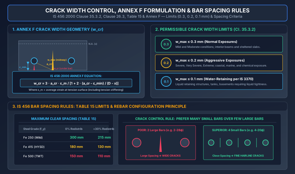
Under IS 456:2000 Clause 35.3.2, the design surface crack width must not exceed the following statutory thresholds under service load combinations:
                         STATUTORY CRACK WIDTH THRESHOLDS
                                        │
             ┌──────────────────────────┼──────────────────────────┐
             ▼                          ▼                          ▼
       w_max ≤ 0.3 mm             w_max ≤ 0.2 mm             w_max ≤ 0.1 mm
    (Normal Environments)     (Aggressive Environments)  (Water-Retaining per IS 3370)
 ┌─────────────────────────┐ ┌─────────────────────────┐ ┌─────────────────────────┐
 │ • Mild exposure         │ │ • Severe exposure       │ │ • Water tanks           │
 │ • Moderate exposure     │ │ • Very Severe exposure  │ │ • Liquid storage tanks  │
 │ • Sheltered interiors   │ │ • Extreme exposure      │ │ • Basements resisting   │
 │ • Dry external walls    │ │ • Coastal / Marine air  │ │   hydrostatic pressure  │
 └─────────────────────────┘ └─────────────────────────┘ └─────────────────────────┘
- Normal Environmental Exposures ():
Applicable to structures subjected to Mild and Moderate exposure conditions (e.g., protected interior members, beams in dry climates, surfaces sheltered from heavy rainfall). Surface crack widths up to do not impair structural aesthetics or promote corrosion in non-aggressive air. - Aggressive Environmental Exposures ():
Applicable to structures subjected to Severe, Very Severe, or Extreme exposure conditions (e.g., coastal marine environments, structures exposed to salt spray, industrial corrosive atmospheres, alternate wetting and drying). The tighter limit prevents capillary suction and moisture diffusion that depassivates the steel rebar. - Liquid-Retaining Structures ( or Uncracked):
For structures designed under IS 3370 (Part 2) for water and sewage storage, crack widths must not exceed under service conditions to prevent through-thickness leakage. Under critical retaining faces, sections are frequently designed as uncracked elastic sections under service loads.
3. Deemed-to-Satisfy Detailing: Bar Spacing Rules (Table 15)
In standard building practice, explicit calculation of crack widths is exempted if the reinforcement detailing satisfies the Maximum Clear Spacing Rules of IS 456 Clause 26.3.2 and Table 15.
3.1 Maximum Clear Distance Between Tension Bars (Table 15)
The maximum clear horizontal distance between adjacent parallel longitudinal bars in a tension face depends upon the steel yield strength and the percentage of moment redistribution:
| Reinforcing Steel Grade | 0% Redistribution (Elastic Analysis) | +15% Redistribution | +30% Redistribution |
|---|---|---|---|
| Mild Steel (Fe 250) | 300 mm | 255 mm | 215 mm |
| HYSD / TMT (Fe 415) | 180 mm | 155 mm | 130 mm |
| HYSD / TMT (Fe 500) | 150 mm | 130 mm | 110 mm |
Physical Principle: Higher strength steels (Fe 415, Fe 500) operate at substantially higher service tensile stresses (). Higher steel strains widen cracks; therefore, higher grade steels require closer bar spacing to distribute tensile strains into a multitude of micro-cracks rather than a few wide fissures.
3.2 Minimum Distance Between Bars (Clause 26.3.1)
To ensure unhindered concrete placement, aggregate passage, and thorough compaction around rebar:
- Individual Bars: Clear horizontal distance between parallel bars shall be not less than the greatest of:
- The diameter of the bar (if diameters are equal).
- The diameter of the larger bar (if diameters are unequal).
- more than the nominal maximum size of coarse aggregate (e.g. for aggregate, minimum clear distance ).
- Vertical Clearance between Layers: Where tension reinforcement is arranged in two or more layers, the bars must be placed directly above each other, and a clear vertical distance of at least must be maintained using cross-spacer bars.
3.3 The Golden Rule of Crack Control: Many Small Bars vs Few Large Bars
A fundamental axiom of structural reinforced concrete detailing is:
                       EFFECT OF BAR SIZE & SPACING ON CRACKING
           FEW LARGE BARS (e.g. 2-28ϕ)                  MANY SMALL BARS (e.g. 4-20ϕ)
           Ast = 1232 mm²                               Ast = 1257 mm²
           Spacing = 168 mm                             Spacing = 48 mm
    ┌──────────────────────────────────────┐     ┌──────────────────────────────────────┐
    │  [  ]                          [  ]  │     │  [ ]     [ ]     [ ]     [ ]         │
    │    │                             │   │     │   │       │       │       │          │
    │    ▼                             ▼   │     │   ▼       ▼       ▼       ▼          │
    │  Large gap between bars               │     │ Closely spaced bars                  │
    │  Results in WIDE, ISOLATED CRACKS    │     │ Results in FINE, HAIRLINE CRACKS     │
    │  w_max ≈ 0.25 - 0.35 mm              │     │ w_max ≈ 0.06 - 0.09 mm (Superior!)   │
    └──────────────────────────────────────┘     └──────────────────────────────────────┘
4. Rigorous Calculation of Crack Width (IS 456 Annex F)
Where explicit crack width verification is required (e.g. marine structures, bridge girders, water tanks, containment structures), the design surface crack width is computed using the formula given in IS 456:2000 Annex F:
Where:
- = Distance from the point considered on the concrete surface to the nearest longitudinal bar surface ().
- Directly under a bar: .
- Midway between two bars spaced at center-to-center distance :
- = Minimum clear cover to the longitudinal tension reinforcement ().
- = Overall depth of the cross-section ().
- = Depth of the neutral axis of the cracked transformed section ().
- = Average strain at the level considered, corrected for tension stiffening (the tensile contribution of intact concrete between cracks):
Where:
- = Calculated strain at the level considered under elastic cracked section theory:
- = Tensile stress in steel reinforcement under service load moment .
- = Internal flexural lever arm.
- = Distance from the compression face to the point where crack width is calculated ( for extreme tension face).
- = Width of the section at the centroid of tension reinforcement ( for rectangular beams; for flanged beams).
5. Durability Framework & Environmental Exposure (Table 3)
Concrete durability is defined as the ability of concrete to resist weathering action, chemical attack, abrasion, and any other process of deterioration during its intended service life.
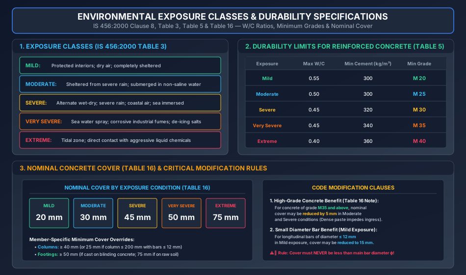
IS 456:2000 Clause 8.2.2 classifies environmental exposures into Five Standard Conditions (Table 3):
                            FIVE EXPOSURE CLASSIFICATIONS
                                          │
        ┌────────────┬─────────────┬──────┴──────┬──────────────┬────────────┐
        ▼            ▼             ▼             ▼              ▼            ▼
      MILD       MODERATE       SEVERE      VERY SEVERE      EXTREME      SPECIAL
    (Indoor)    (Rain/Water)   (Coastal)     (Sea Spray)     (Tidal)     (Chemical)
- Mild: Concrete surfaces protected against weather or aggressive conditions (e.g. interior of residential/office buildings, sheltered basements).
- Moderate: Concrete surfaces sheltered from severe rain or freezing whilst wet; concrete continuously submerged under non-saline water; concrete in contact with non-aggressive soils.
- Severe: Concrete surfaces exposed to severe rain, alternate wetting and drying, coastal environments, or completely immersed in sea water.
- Very Severe: Concrete surfaces exposed to sea water spray, corrosive industrial fumes, or freezing conditions while wet in contact with de-icing salts.
- Extreme: Concrete surfaces in the tidal splash zone of oceans, or in direct contact with highly aggressive liquid chemicals or acidic groundwaters.
6. Concrete Mix Requirements for Durability (Table 5)
To ensure that concrete paste has low permeability and high resistance to chemical ingress, IS 456 Table 5 enforces three interrelated parameters:
- Maximum Free Water-Cement Ratio (): Lower W/C ratio decreases capillary porosity.
- Minimum Cement Content (): Guarantees alkaline passivating reserve around steel ().
- Minimum Grade of Concrete: Ensures paste density and microstructure refinement.
Comprehensive IS 456 Table 5 Matrix for Plain (PCC) and Reinforced Concrete (RCC):
| Environmental Exposure | Plain Concrete (PCC) | Reinforced Concrete (RCC) | ||||
|---|---|---|---|---|---|---|
| Max W/C | Min Cement () | Min Grade | Max W/C | Min Cement () | Min Grade | |
| Mild | 0.60 | 220 | — | 0.55 | 300 | M 20 |
| Moderate | 0.60 | 240 | M 15 | 0.50 | 300 | M 25 |
| Severe | 0.50 | 250 | M 20 | 0.45 | 320 | M 30 |
| Very Severe | 0.45 | 260 | M 20 | 0.45 | 340 | M 35 |
| Extreme | 0.40 | 280 | M 25 | 0.40 | 360 | M 40 |
Critical Exam Distinction:
- For RCC, the absolute minimum permissible concrete grade under any circumstance is M 20 (for Mild exposure).
- For PCC, structural plain concrete starts at M 15 (for Moderate exposure).
- In marine environments (Severe/Very Severe), the minimum grade for RCC is M 30 / M 35.
7. Nominal Concrete Cover Requirements (Clause 26.4 & Table 16)
Nominal cover is the design depth of concrete cover to all steel reinforcement (including stirrups, links, and main bars). It protects steel against chemical depassivation and provides thermal insulation during fires.
7.1 Nominal Cover per IS 456 Table 16 (for aggregate):
- Mild Exposure:
- Moderate Exposure:
- Severe Exposure:
- Very Severe Exposure:
- Extreme Exposure:
                       NOMINAL COVER TO REINFORCEMENT
       20 mm             30 mm             45 mm             50 mm             75 mm
    ┌─────────┐       ┌─────────┐       ┌─────────┐       ┌─────────┐       ┌─────────┐
    │  MILD   │       │MODERATE │       │ SEVERE  │       │VERY SEV.│       │ EXTREME │
    └─────────┘       └─────────┘       └─────────┘       └─────────┘       └─────────┘
7.2 Statutory Modification Rules for Nominal Cover:
- High-Grade Concrete Benefit (Table 16 Note):
For concrete of grade M 35 and above, the nominal cover may be reduced by in Moderate and Severe conditions.
(Notice: This reduction does NOT apply to Very Severe or Extreme conditions!). - Small Bar Diameter Benefit (Mild Exposure):
For longitudinal reinforcing bars of diameter in Mild exposure, the nominal cover may be reduced by (to ). - Absolute Non-Negotiable Limit:
Nominal cover shall in no case be less than the diameter of the main reinforcing bar . - Member-Specific Minimum Covers:
- Columns: Minimum cover (or if column dimension with bars ).
- Footings: Minimum cover (if cast against blinding concrete layer; minimum if cast directly against unformed soil).
8. High-Precision Engineering Diagrams
8.1 Environmental Exposure Classes & Durability Specifications
The diagram below details the 5 environmental exposure classes (Table 3), the full W/C ratio, minimum cement, and minimum grade matrix (Table 5), and the nominal cover requirements with special reduction rules (Table 16).
8.2 Crack Width Control, Annex F Formulation & Bar Spacing Rules
The diagram below details Annex F crack width geometry (), permissible limits (), Table 15 maximum spacing rules, and the physical comparison demonstrating the superiority of closely spaced small-diameter bars.
9. Pre-Calculated Solved Numerical Examples
Problem 1: Complete Durability Design for Coastal Marine Jetty (GATE CE / SSC JE)
Statement:
A reinforced concrete jetty structure is constructed along a sea coast where the super-structure beams are exposed to intense sea water spray (classified as Very Severe environmental exposure condition).
Determine from IS 456:2000 provisions:
- The maximum permissible free water-cement ratio.
- The minimum cement content ().
- The minimum concrete grade permitted.
- The nominal concrete cover required if concrete grade M35 is specified. State whether the cover reduction applies.
Solution:
From IS 456:2000 Table 3, exposure to sea water spray is explicitly categorized as Very Severe.
- Maximum Free Water-Cement Ratio:
From Table 5 for Reinforced Concrete under Very Severe exposure: - Minimum Cement Content:
From Table 5 for Reinforced Concrete under Very Severe exposure: - Minimum Concrete Grade:
From Table 5 for Reinforced Concrete under Very Severe exposure: - Nominal Concrete Cover:
From Table 16, the base nominal cover for Very Severe exposure is .
Evaluation of Reduction Clause:
IS 456 Table 16 note states: "For concrete of grade M35 and above, the nominal cover may be reduced by in Moderate and Severe conditions."
Because the exposure is Very Severe, the reduction is legally not applicable.
Therefore:
Problem 2: Theoretical Calculation of Surface Crack Width per Annex F (UPSC ESE / GATE CE)
Statement:
A rectangular reinforced concrete beam has width , overall depth , and effective depth . Clear cover to longitudinal reinforcement is .
The beam is reinforced with 3 bars of diameter () distributed across the width.
Under service loads, the bending moment at midspan is .
Materials are concrete M25 (, , ) and steel Fe 415 (, modular ratio ).
Using IS 456 Annex F:
- Determine the service stress in steel and average strain .
- Calculate the surface crack width directly beneath a bar ().
- Calculate the surface crack width midway between the bars.
- Verify whether the crack widths comply with permissible limits for Severe exposure ().
Step 1: Cracked Neutral Axis () and Lever Arm ()
Equating first moments of area of transformed cracked section:
Dividing by 150:
Lever arm :
Step 2: Steel Stress () and Strains ()
Strain in steel:
Strain at the bottom tension face ():
Tension stiffening correction term:
Average strain :
Step 3: Crack Width Directly Beneath a Bar ()
Here . Thus .
Step 4: Crack Width Midway Between Bars
For 3 bars of dia distributed across with :
Distance from the surface point midway between bars to the nearest bar surface:
Denominator term in Annex F:
Step 5: Compliance Check
- Maximum crack width occurs midway between bars: .
- Permissible limit for Severe exposure: .
Problem 3: Bar Spacing and Detailing Verification (SSC JE / State AE)
Statement:
A reinforced concrete beam has web width . Clear side cover to stirrups is , and diameter stirrups are provided. The longitudinal steel grade is Fe 415 ( redistribution).
Two alternative reinforcement layouts are proposed to provide :
- Option A: 2 bars of diameter ().
- Option B: 4 bars of diameter ().
Evaluate both options for compliance with IS 456 Table 15 maximum clear spacing limits and minimum spacing limits (assume nominal maximum aggregate size is ). Recommend the superior option.
Solution:
Available width between inside faces of stirrups:
Evaluation of Option A (2 bars of 28 mm dia):
- Number of spaces between bars .
- Total width occupied by steel .
- Clear distance between bars:
- Check IS 456 Table 15 Max Spacing Limit:
For Fe 415 with 0% redistribution, maximum clear spacing .
Since , Option A satisfies Table 15. - Check Minimum Spacing Limit: Since , clear spacing is adequate for compaction.
Evaluation of Option B (4 bars of 20 mm dia):
- Number of spaces between bars .
- Total width occupied by steel .
- Clear distance between bars:
- Check IS 456 Table 15 Max Spacing Limit:
Fully compliant. - Check Minimum Spacing Limit: Since , concrete can be placed and vibrated without aggregate bridging.
Engineering Comparison & Final Recommendation:
While both options technically satisfy Table 15, Option B is overwhelmingly superior for crack control:
- In Option A, the clear spacing of is barely within the limit. Wide gaps between bars allow unreinforced surface concrete to develop wide flexural cracks midway between bars ().
- In Option B, the clear spacing of confines the concrete into tiny zones, forcing tensile cracks to remain ultra-fine hairline fissures ().
- Recommendation: Adopt Option B (4 bars of dia).
10. Comparative Analysis: Durability & Crack Control Parameters
| Parameter | Mild Exposure | Moderate Exposure | Severe Exposure | Very Severe Exposure | Extreme Exposure |
|---|---|---|---|---|---|
| Max Permissible Crack Width | |||||
| Max Free W/C Ratio (RCC) | 0.55 | 0.50 | 0.45 | 0.45 | 0.40 |
| Min Cement Content (RCC) | |||||
| Min Concrete Grade (RCC) | M 20 | M 25 | M 30 | M 35 | M 40 |
| Nominal Cover (Base) | |||||
| Cover Reduction for M35+ | No | Yes () | Yes () | No | No |
11. Common Misconceptions & Exam Traps
[!WARNING]
Extending the 5 mm Cover Reduction to Very Severe/Extreme:
A widespread error in competitive exams is reducing cover by whenever grade M35 or higher is specified.
Code Rule: IS 456 Table 16 Note explicitly limits the reduction to MODERATE and SEVERE exposures only. For Very Severe () and Extreme (), no reduction is permitted.Assuming Minimum Grade for RCC in Mild Exposure is M 15:
The minimum grade for structural reinforced concrete (RCC) under IS 456 is M 20, even in protected interior Mild environments. M 15 is strictly for Plain Concrete (PCC).Confusing Maximum Aggregate Size Clear Spacing:
Clear horizontal spacing between bars must be at least (i.e. for aggregate), not just equal to the aggregate size.Table 15 Redistribution Reduction Error:
When positive moment is redistributed into negative moment regions by , the allowable spacing in Table 15 decreases (from to for Fe 415), because higher rotation demands closer bar spacing to control crack opening.
12. Practice Questions for Self-Assessment
- GATE CE: What is the minimum grade of reinforced concrete and minimum nominal cover required for a coastal structure exposed to severe marine environment according to IS 456:2000?
(Answer: Minimum grade M 30, nominal cover ) - UPSC ESE: A rectangular beam reinforced with Fe 415 steel has a clear spacing of between tension bars. If no moment redistribution was carried out, does this beam comply with IS 456:2000 crack control rules?
(Answer: No; Table 15 limits maximum clear spacing to for Fe 415 at 0% redistribution) - SSC JE / State AE: What is the maximum permissible crack width for reinforced concrete members exposed to normal indoor conditions?
(Answer: ) - RRB JE: What is the minimum nominal cover specified for reinforced concrete footings cast against a blinding lean concrete layer?
(Answer: )