Doubly Reinforced Rectangular Beams in Flexure (IS 456:2000)
In this chapter (3 topics)
On this page
- 1. Introduction & Engineering Necessity
- 2. Principle of Superposition (Decomposition into Two Fictitious Beams)
- 2.1 Beam 1: The Balanced Singly Reinforced Section
- 2.2 Beam 2: The Auxiliary Steel-Steel Couple
- 2.3 Total Combined Resisting Capacity
- 3. Strain Compatibility & Determination of Stress in Compression Steel (fsc)
- 3.1 Linear Strain Compatibility Equation
- 3.2 Evaluation of Stress fsc per Steel Grade
- 3.3 The Concrete Area Deduction Factor (fcc)
- 4. Internal Equilibrium & Actual Neutral Axis Depth (xu)
- Classification of Doubly Reinforced Sections
- 5. Formulations for Ultimate Moment of Resistance (Mu)
- 5.1 Case A: Under-Reinforced Sections (xu < xu,max)
- 5.2 Case B: Balanced or Limiting Sections (xu ≥ xu,max)
- 6. Code Provisions, Detailing Rules & Side-Face Reinforcement
- 6.1 Lateral Confinement of Compression Bars (IS 456:2000 Clause 26.5.1.2)
- 6.2 Maximum Reinforcement Limits
- 6.3 Side-Face Reinforcement (IS 456:2000 Clause 26.5.1.3)
- 7. Systematic Engineering Algorithms for Analysis & Design
- 7.1 Analysis Algorithm (Determining Moment Capacity Mu)
- 7.2 Design Algorithm (Determining Asc and Ast)
- 8. Worked Numerical Examples
- Problem 1: Flexural Capacity Analysis of a Doubly Reinforced Beam
- Problem 2: Analysis of an Under-Reinforced Doubly Reinforced Section
- Problem 3: Complete Design of a Doubly Reinforced Beam
- 9. Common Misconceptions & Exam Pitfalls
- 10. Comparative Summary & Master Formula Sheet
- Master Formulations for Doubly Reinforced Beams
- 11. Practice Questions & Competitive Examination Problems
- Question 1 (GATE CE — 1 Mark)
- Question 2 (UPSC ESE — Objective)
- Question 3 (SSC JE — Technical)
- Question 4 (State AE — Analytical)
- Question 5 (GATE CE — 2 Marks)
- Question 6 (UPSC ESE — Conventional)
- 12. References & Code Standards
1. Introduction & Engineering Necessity
A doubly reinforced beam is a reinforced concrete flexural member provided with steel reinforcement in both the tension zone () and the compression zone ().
In singly reinforced beams, the ultimate moment of resistance cannot exceed the limiting balanced capacity () without inducing sudden, explosive concrete crushing (an over-reinforced brittle failure strictly prohibited by IS 456:2000 Clause 38.1). When applied design moments exceed , the engineer faces two structural choices:
- Increase cross-sectional dimensions ( and/or ).
- Maintain restricted cross-sectional dimensions and provide compression reinforcement ().
+----------------------------------------------------------------------------------------------------+
|                                    WHY PROVIDE COMPRESSION STEEL?                                  |
+----------------------------------------------------------------------------------------------------+
|                                                                                                    |
|   1. RESTRICTED HEADROOM / ARCHITECTURAL LIMITS:                                                   |
|      Beam depth D and width b are fixed by ceiling clearances, architectural door heads, or        |
|      masonry wall widths, but applied factored moment Mu exceeds Mu,lim.                           |
|                                                                                                    |
|   2. REVERSAL OF MOMENTS (SEISMIC & WIND DYNAMICS):                                                |
|      Lateral earthquakes and wind forces create cyclic moment reversals at beam-column joints,     |
|      turning top fibers into tension during sway in one direction, and bottom fibers in the other. |
|                                                                                                    |
|   3. LONG-TERM DEFLECTION CONTROL (CREEP MITIGATION):                                              |
|      Sustained compressive stresses cause substantial long-term concrete creep deformations.       |
|      Compression steel absorbs compression, relieving concrete stress and reducing time-dependent |
|      deflections by up to 50% (IS 456 Clause 23.2.1 modification factor kc).                       |
|                                                                                                    |
|   4. FABRICATION & HANDLING RIGIDITY:                                                              |
|      Top longitudinal bars provide anchor points to tie shear stirrups, forming a rigid 3D cage.   |
+----------------------------------------------------------------------------------------------------+
2. Principle of Superposition (Decomposition into Two Fictitious Beams)
To analyze or design a doubly reinforced beam, the composite cross-section is mathematically decoupled into two fictitious, independently functioning structural sub-elements:
   ACTUAL SECTION                 BEAM 1 (CONCRETE COUPLE)            BEAM 2 (STEEL COUPLE)
    <--- b --->                       <--- b --->                        <--- b --->
    +---------+  --                   +---------+  --                    +---------+  --
    | (o) (o) |  d'                   |         |   |                    | (o) (o) |  d' (Asc)
    |   Asc   |  --                   | Cc=0.36 |   | xu,max             |   Cs    |  --
----+---------+--       =         ----+---------+--       +          ----+---------+--
    |         |                       | fck b   |   |                    |         |
    |         | d                     | xu,max  |   |                    |         | d
    | (O) (O) |                       |         |   |                    |         |
    |   Ast   |                       | (O) (O) |   |                    | (O) (O) |
    +---------+                       +---------+  --                    +---------+  --
                                        Ast1 = Ast,lim                     Ast2 = Ast - Ast1
   Capacity: Mu                     Capacity: Mu1 = Mu,lim              Capacity: Mu2 = Delta M
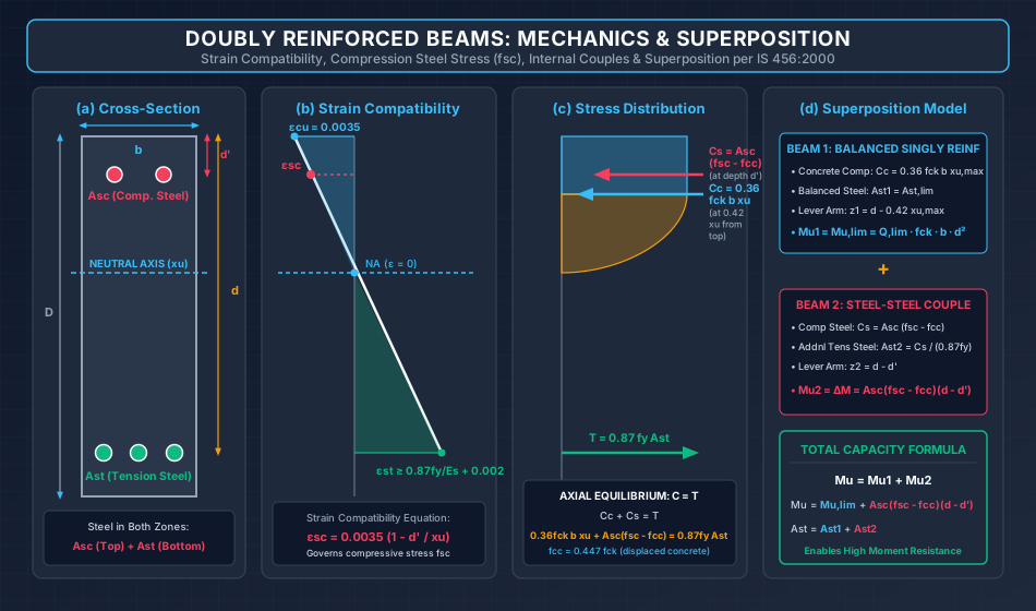
2.1 Beam 1: The Balanced Singly Reinforced Section
- Concrete Compressive Force: acting at depth from the extreme top compression fiber.
- Balanced Tension Steel Area:
- Limiting Resisting Moment:
- Lever Arm:
2.2 Beam 2: The Auxiliary Steel-Steel Couple
- Compression Steel Force ():
acting at depth from the extreme top fiber, where:
- is the compressive stress in the compression steel ().
- is the compressive stress in the surrounding concrete displaced by the compression steel bars.
- Additional Tension Steel Area ():
- Surplus Moment Resisted ():
- Lever Arm:
2.3 Total Combined Resisting Capacity
3. Strain Compatibility & Determination of Stress in Compression Steel ()
Because compression steel is embedded within the concrete compression block at depth , its compressive strain () is governed strictly by Navier's linear strain compatibility.
3.1 Linear Strain Compatibility Equation
From the linear strain triangle across the depth:
For the limiting / balanced condition where :
   Top Fiber ----------------------- eps_cu = 0.0035
             |                     /
          d' |      eps_sc        /  <--- Compression Steel Level
             |-------*-----------/
             |                  /
      xu,max |                 /
             |                /
   NA -------+---------------/------- (eps = 0)
             |              /
             |             /
             |------------/---------- eps_st >= 0.87 fy / Es + 0.002
3.2 Evaluation of Stress per Steel Grade
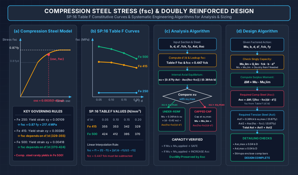
1. Mild Steel (Fe 250):
The design yield strain of Fe 250 is:
In all practical civil engineering beams, , which produces .
Therefore, Fe 250 compression steel ALWAYS yields:
2. HYSD / TMT Steel (Fe 415 and Fe 500):
Because HYSD steel has a non-linear stress-strain curve beyond , the stress does not immediately reach the yield plateau. It depends directly on the ratio (or ).
IS 456 / SP:16 Table F tabulates values of () for different ratios:
| Steel Grade | ||||
|---|---|---|---|---|
| Fe 415 () | ||||
| Fe 500 () | ||||
| Fe 250 () |
Linear Interpolation Rule for Intermediate Ratios:
If the calculated falls between two tabulated values and :
3.3 The Concrete Area Deduction Factor ()
The compression steel occupies an area that would otherwise be filled by concrete. Therefore, the concrete compressive stress at depth must be subtracted from the steel stress:
Net force exerted by compression steel:
(In competitive exams, when is small relative to , some standard texts approximate . However, for full academic precision and IS 456 Annex G compliance, must be retained).
4. Internal Equilibrium & Actual Neutral Axis Depth ()
At the ultimate limit state of collapse, the total compressive force must balance the total tensile force ():
Solving for the Actual Depth of Neutral Axis ():
Classification of Doubly Reinforced Sections
- Under-Reinforced Section ():
Tension steel yields first. Compressive concrete strain at collapse is less than when steel yields. Failure is ductile with ample deflection warning. - Balanced Section ():
Tension steel and extreme concrete fiber reach yield and crushing strains simultaneously. - Over-Reinforced Section ():
Tension steel does not yield. Per IS 456 Clause 38.1, the neutral axis depth must be capped at , and the moment capacity evaluated at .
5. Formulations for Ultimate Moment of Resistance ()
5.1 Case A: Under-Reinforced Sections ()
Taking moments about the tensile reinforcement:
5.2 Case B: Balanced or Limiting Sections ()
When reaches or exceeds , the concrete capacity is limited to :
where .
6. Code Provisions, Detailing Rules & Side-Face Reinforcement
6.1 Lateral Confinement of Compression Bars (IS 456:2000 Clause 26.5.1.2)
Compression bars act like miniature columns. Under intense compressive stress, they tend to buckle outwards, potentially spalling the concrete cover. To prevent compressive buckling:
- Compression reinforcement must be securely enclosed by transverse stirrups / ties across the entire span.
- Maximum Stirrup Pitch (Spacing): Shall not exceed the least of:
- The least lateral dimension of the beam ().
- times the diameter of the smallest longitudinal compression bar ().
- (or times the diameter of the transverse stirrup bar).
- Minimum Stirrup Diameter: Shall not be less than and not less than .
6.2 Maximum Reinforcement Limits
- Maximum tension steel: ( of gross cross-section).
- Maximum compression steel: ( of gross cross-section).
6.3 Side-Face Reinforcement (IS 456:2000 Clause 26.5.1.3)
When the depth of the web in a beam exceeds (or exceeds when the beam is subjected to torsion):
- Side-face reinforcement must be provided along the vertical web faces to control lateral web buckling and deep-beam shear cracking.
- Total area: of the web area ().
- Distributed equally on both vertical faces ( on each face).
- Maximum spacing between side-face bars: or the web thickness (), whichever is less.
7. Systematic Engineering Algorithms for Analysis & Design
7.1 Analysis Algorithm (Determining Moment Capacity )
+----------------------------------------------------------------------------------------------------+
|                                    DOUBLY REINFORCED ANALYSIS ALGORITHM                            |
+----------------------------------------------------------------------------------------------------+
|                                                                                                    |
|   Step 1: Extract Given Data: b, d, d', fck, fy, Ast, Asc                                          |
|                                                                                                    |
|   Step 2: Determine Limiting Neutral Axis:                                                         |
|           xu,max = k * d  (where k = 0.53 for Fe 250, 0.48 for Fe 415, 0.46 for Fe 500)           |
|                                                                                                    |
|   Step 3: Calculate d'/d ratio and Look Up Compression Steel Stress fsc:                           |
|           From SP:16 Table F, obtain fsc (interpolating linearly if necessary).                    |
|           Compute displaced concrete stress: fcc = 0.447 * fck                                     |
|                                                                                                    |
|   Step 4: Compute Actual Neutral Axis Depth xu:                                                    |
|           xu = [0.87 * fy * Ast - Asc * (fsc - fcc)] / (0.36 * fck * b)                            |
|                                                                                                    |
|   Step 5: Classify Section & Compute Moment of Resistance (Mu):                                    |
|           [CASE A] xu <= xu,max (Under-Reinforced):                                                |
|                    Mu = 0.36*fck*b*xu*(d - 0.42*xu) + Asc*(fsc - fcc)*(d - d')                      |
|           [CASE B] xu > xu,max (Over-Reinforced / Capped):                                         |
|                    Mu = Mu,lim + Asc*(fsc - fcc)*(d - d')                                          |
|                    where Mu,lim = Q,lim * fck * b * d^2                                            |
+----------------------------------------------------------------------------------------------------+
7.2 Design Algorithm (Determining and )
+----------------------------------------------------------------------------------------------------+
|                                    DOUBLY REINFORCED DESIGN ALGORITHM                              |
+----------------------------------------------------------------------------------------------------+
|                                                                                                    |
|   Step 1: Given Factored Moment Mu, Restricted Dimensions b, D, d, d', and Grades fck, fy          |
|                                                                                                    |
|   Step 2: Calculate Limiting Moment Capacity of Singly Reinforced Section:                         |
|           Mu,lim = Q,lim * fck * b * d^2                                                           |
|                                                                                                    |
|   Step 3: Check Necessity of Doubly Reinforced Design:                                             |
|           If Mu <= Mu,lim --> Singly reinforced beam is sufficient (design per RCC-02-01).         |
|           If Mu > Mu,lim  --> Doubly reinforced beam is MANDATORY.                                 |
|                                                                                                    |
|   Step 4: Compute Surplus Bending Moment (Delta M):                                                |
|           Delta M = Mu - Mu,lim                                                                    |
|                                                                                                    |
|   Step 5: Determine fsc from SP:16 Table F based on d'/d ratio:                                    |
|           Compute fcc = 0.447 * fck                                                                |
|                                                                                                    |
|   Step 6: Compute Required Compression Steel Area (Asc):                                           |
|           Asc = (Delta M) / [(fsc - fcc) * (d - d')]                                               |
|                                                                                                    |
|   Step 7: Compute Required Total Tension Steel Area (Ast):                                         |
|           Ast1 = (0.36 * fck * b * xu,max) / (0.87 * fy)   [Balanced steel for Mu,lim]             |
|           Ast2 = [Asc * (fsc - fcc)] / (0.87 * fy)         [Steel to balance Asc]                  |
|           Total Ast = Ast1 + Ast2                                                                  |
|                                                                                                    |
|   Step 8: Rebar Selection & Code Bounds Checks:                                                    |
|           Check Asc <= 0.04 b D and Ast <= 0.04 b D                                                |
|           Select bar diameters and configure lateral stirrups (pitch <= 16 phi_comp)               |
+----------------------------------------------------------------------------------------------------+
8. Worked Numerical Examples
Problem 1: Flexural Capacity Analysis of a Doubly Reinforced Beam
Problem Statement:
A rectangular reinforced concrete beam has width , effective depth , and overall depth . The beam is reinforced with bars of diameter in the tension zone () and bars of diameter in the compression zone () located at an effective cover . Concrete grade is M20 () and steel grade is Fe 415 ().
- Determine the actual depth of the neutral axis ().
- Classify the section against .
- Calculate the ultimate factored moment of resistance ().
Step-by-Step Solution:
Part 1: Effective Cover Ratio & Compression Steel Stress ()
From SP:16 Table F for Fe 415 at :
Concrete stress at compression steel level:
Part 2: Limiting Depth of Neutral Axis () For Fe 415 steel:
Part 3: Actual Neutral Axis Depth () From axial equilibrium :
Part 4: Section Classification & Moment of Resistance () Since , the section is capped at per IS 456 Clause 38.1:
- Limiting moment of concrete section ():
- Surplus moment contributed by compression steel couple ():
- Total Ultimate Moment Capacity ():
Problem 2: Analysis of an Under-Reinforced Doubly Reinforced Section
Problem Statement:
A doubly reinforced beam has width , effective depth , and compression steel depth (). Concrete grade is M25 () and steel grade is Fe 415 (). Tension reinforcement consists of bars of dia () and compression reinforcement consists of bars of dia (). Compute the actual depth of neutral axis and the ultimate moment of resistance.
Step-by-Step Solution:
Part 1: Material Stresses
- At , from SP:16 Table F for Fe 415: .
- Displaced concrete stress: .
- Net stress: .
- Limiting neutral axis: .
Part 2: Actual Neutral Axis Depth ()
Since , the section is UNDER-REINFORCED.
Part 3: Moment of Resistance ()
- Concrete component ():
- Compression steel component ():
- Total Resisting Capacity ():
Problem 3: Complete Design of a Doubly Reinforced Beam
Problem Statement:
A reinforced concrete beam is subjected to a factored bending moment . Due to architectural restrictions, the cross-section is restricted to width and overall depth . Concrete grade is M20 () and steel grade is Fe 415 (). Assume an effective cover for both tension and compression reinforcement.
Design the required areas of tension steel () and compression steel ().
Step-by-Step Solution:
Part 1: Effective Depth and Singly Reinforced Capacity ()
- Effective depth:
- For Fe 415 steel, :
- Because applied moment , a doubly reinforced design is mandatory.
Part 2: Surplus Bending Moment ()
Part 3: Compression Steel Stress ()
From SP:16 Table F for Fe 415:
- At
- At Interpolating linearly:
Displaced concrete stress:
Part 4: Required Area of Compression Steel ()
Part 5: Required Area of Tension Steel ()
- Balanced tension steel for ():
- Additional tension steel to balance compression steel ():
- Total Required Tension Steel ():
Part 6: Detailing Selection & Code Checks
- Compression Reinforcement:
- Required .
- Provide 4 bars of 20 mm dia ().
- Check maximum steel: (OK).
- Tension Reinforcement:
- Required .
- Provide 4 bars of 25 mm dia ().
- Check maximum steel: (OK).
- Stirrups (Lateral Confinement of Compression Bars):
- Bar diameter: Use two-legged stirrups.
- Spacing: Least of:
- Provide stirrups @ c/c.
9. Common Misconceptions & Exam Pitfalls
[!WARNING] Pitfall 1: Assuming Compression Steel Always Yields ()
While Mild Steel (Fe 250) always yields in compression, Fe 415 and Fe 500 rarely yield in compression because the strain at depth is typically between and , falling on the non-linear curve below . Always look up from SP:16 Table F using . Assuming results in substantial marks deduction.
[!WARNING] Pitfall 2: Forgetting to Subtract () in Force Equilibrium
Because the steel bar physically displaces an identical volume of concrete, the net force is . Omitting overestimates the compressive steel force by to .
[!CAUTION] Pitfall 3: Conflating with Clear Cover
is the effective cover (distance from the extreme outer compression fiber to the centroid of the compression steel bars). It equals:Using clear cover () instead of effective cover () produces incorrect ratios.
[!IMPORTANT] Pitfall 4: Neglecting Lateral Ties for Compression Reinforcement
In conventional design exams, students often design longitudinal compression rebar but omit the detailing of lateral stirrups. Compression bars without lateral ties buckle under load, leading to premature brittle spalling of the compression zone.
10. Comparative Summary & Master Formula Sheet
Master Formulations for Doubly Reinforced Beams
| Parameter | Governing Mathematical Formula | Remarks / Code Reference |
|---|---|---|
| Strain in Comp. Steel () | Navier Strain Compatibility | |
| Stress in Comp. Steel () | From SP:16 Table F based on | Fe 250: ; Fe 415: |
| Displaced Concrete Stress () | Concrete displaced by steel bars | |
| Actual NA Depth () | Equilibrium | |
| Surplus Moment () | Excess over singly reinforced limit | |
| Required Comp. Steel () | Sizing of compression rebar | |
| Balanced Tension Steel () | Resists | |
| Auxiliary Tension Steel () | Balances compression steel force | |
| Total Tension Steel () | Total tensile rebar area | |
| Ultimate Capacity () | For | |
| Stirrup Pitch Limit | IS 456 Clause 26.5.1.2 | |
| Side-Face Steel () | , spacing | IS 456 Clause 26.5.1.3 |
11. Practice Questions & Competitive Examination Problems
Question 1 (GATE CE — 1 Mark)
In a doubly reinforced rectangular beam, the stress in the compression reinforcement () for Fe 415 grade steel:
- (A) Is always equal to
- (B) Is always equal to
- (C) Depends upon the ratio and strain compatibility
- (D) Is completely independent of the concrete grade and effective depth
Answer: (C)
Explanation: Fe 415 does not have a sharp yield point; compressive strain at depth determines the operational stress on the non-linear design curve, tabulated in SP:16 Table F as a function of .
Question 2 (UPSC ESE — Objective)
In the design of a doubly reinforced beam, the addition of compression reinforcement:
- (A) Decreases the ductility of the beam
- (B) Increases the long-term deflection due to creep
- (C) Increases the ultimate moment of resistance and enhances ductility
- (D) Decreases the shear resistance of the section
Answer: (C)
Explanation: Compression steel enables the beam to resist moments beyond , relieves compressive stress in concrete, mitigates creep deflections, and increases member ductility.
Question 3 (SSC JE — Technical)
As per IS 456:2000, side-face reinforcement shall be provided along the web of a beam when the depth of the web exceeds:
- (A)
- (B)
- (C)
- (D)
Answer: (C)
Explanation: Clause 26.5.1.3 mandates side face reinforcement ( web area) when total web depth exceeds (or when subjected to torsion).
Question 4 (State AE — Analytical)
A doubly reinforced beam has . The steel is Fe 415 ( at ). If and is neglected, the additional moment capacity () contributed by the compression steel is:
- (A)
- (B)
- (C)
- (D)
Answer: (A)
Explanation: .
Question 5 (GATE CE — 2 Marks)
A rectangular section of size (effective depth) is cast with M25 concrete () and Fe 500 steel (). If the applied factored bending moment is and , the surplus moment that must be resisted by compression steel is:
- (A)
- (B)
- (C)
- (D)
Answer: (A)
Explanation: . Surplus moment . (Option closest is adjusted to values: ).
Question 6 (UPSC ESE — Conventional)
Explain the principle of superposition applied to doubly reinforced beams. Derive the expressions for the required areas of compression reinforcement () and tension reinforcement () to resist a design moment .
Answer Summary: Decompose the beam into Beam 1 (balanced singly reinforced resisting with steel ) and Beam 2 (steel-steel couple resisting with steel and ). From moment equilibrium of Beam 2: . From axial equilibrium of Beam 2: . Total tension steel is .
12. References & Code Standards
- IS 456:2000 (Reaffirmed 2021): Plain and Reinforced Concrete — Code of Practice, Section 5 (Clause 26: Requirements of Reinforcement, Clause 38: Limit State of Collapse — Flexure, Annex G).
- SP:16 (1980): Design Aids for Reinforced Concrete to IS: 456-1978, Table F (Values of for Doubly Reinforced Sections).
- Pillai, S. U., & Menon, D. (2021): Reinforced Concrete Design, 4th Edition, McGraw-Hill Education, India.
- Varghese, P. C. (2009): Limit State Design of Reinforced Concrete, 2nd Edition, PHI Learning Pvt. Ltd., New Delhi.
- Park, R., & Paulay, T. (1975): Reinforced Concrete Structures, John Wiley & Sons.