Centrifugal Pumps: Classification, Velocity Triangles, Manometric Head, Minimum Starting Speed, Multistage Pumps & NPSH
In this chapter (5 topics)
On this page
- 1. Module Overview & Pedagogical Scope
- 2. Official Examination Syllabus Mapping
- 3. Fundamental Physical Principles & Governing Assumptions
- 4. Mathematical Derivations & Rigorous Proofs
- Sub-derivation A: Velocity Triangles & Euler Pump Head Equation
- Sub-derivation B: Vane Curvature Comparison — Why Backward-Curved Vanes Dominate
- Sub-derivation C: Manometric Head (Hm) & Efficiency Formulations
- Sub-derivation D: Minimum Starting Speed (Nmin) & Priming
- Sub-derivation E: Multistage Pumping & Net Positive Suction Head (NPSH)
- 5. Technical Diagrams & Interactive Architectural Schematics
- Figure 1: Centrifugal Pump Volute Casing & Backward-Curved Velocity Triangles
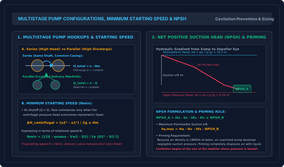
- Figure 2: Multistage Hookups, Minimum Starting Speed & NPSH Hydraulic Gradient
- 6. Comparative Engineering Analysis & Parameter Regimes
- 7. Worked Numerical Examples (Pre-Calculated & Verified)
- Problem 1: Impeller Sizing, Velocity Triangles & Minimum Starting Speed
- Problem 2: Multistage Centrifugal Mine Dewatering Pump
- Problem 3: NPSH Analysis, Suction Lift Limit & Cavitation Inception
- 8. High-Yield Examination Traps & Ambiguities
- 9. Real-World Engineering Applications & Case Studies
- 10. Cross-Disciplinary & Downstream Dependencies
- 11. Summary Formula Cheat Sheet & Memory Anchors
- 12. Comprehensive References & Standard Codes
1. Module Overview & Pedagogical Scope
A centrifugal pump is a rotodynamic hydraulic machine that converts mechanical shaft power into hydraulic pressure energy by subjecting the fluid to centrifugal acceleration. Hydrodynamically, a centrifugal pump is the exact inverse of an inward-flow reaction turbine (Francis runner): whereas a turbine absorbs kinetic and pressure head from the fluid to drive a shaft, a pump transfers mechanical torque from an electric motor or diesel engine into the fluid stream via rotating backward-curved impeller vanes.
Water enters the pump axially through the suction pipe into the central eye of the impeller, turns radially into the divergent vane passages, and is flung outwards at high peripheral speed. As the high-velocity liquid discharges from the impeller rim into the surrounding volute casing or stationary diffuser guide ring, the expanding cross-sectional area decelerates the stream, converting kinetic dynamic head into usable static delivery pressure head.
                  Centrifugal Energy Conversion Path
    ┌───────────────────────────┐         Mechanical Shaft Torque
    │ Electric Motor / Engine   │──────────────────────────────────────┐
    └───────────────────────────┘                                      │
                                                                       ▼
    ┌───────────────────────────┐   Radial Inflow to Eye       ┌───────────────┐
    │ Suction Sump (hs)         ├─────────────────────────────►│ Impeller Disc │
    │ Foot Valve with Strainer  │   Sub-atmospheric Suction    │ Backward Vanes│
    └───────────────────────────┘                              └───────┬───────┘
                                                                       │
                                                                       ▼
    ┌───────────────────────────┐   Kinetic to Static Head     ┌───────────────┐
    │ Delivery Reservoir (hd)   │◄─────────────────────────────┤ Volute Casing │
    │ High Pressure Manometric H│  Diffusing Flow Passage      │ / Diffuser    │
    └───────────────────────────┘                              └───────────────┘
This master technical module establishes the comprehensive fluid mechanics, design proportions, velocity kinematics, operational limits, and cavitation criteria for centrifugal pumping systems:
- Hydraulic architecture of the pump assembly: suction pipe, foot valve, strainer, impeller eye, backward-curved vanes, volute vs vortex casings, and delivery discharge.
- Derivation of velocity triangles at inlet and exit, Euler pump head , and comparative stability analysis of backward-curved (), radial (), and forward-curved () impeller vanes.
- Formulations for Manometric Head (), manometric efficiency (), mechanical efficiency (), and overall plant efficiency ().
- The physical mechanics of Minimum Starting Speed (): centrifugal pressure head generation at shutoff () required to unseat the delivery non-return check valve.
- The imperative necessity of Priming and the role of the foot valve.
- Multistage pumping systems: series connection for high heads () vs parallel connection for high discharge ().
- Cavitation hydrodynamics, Net Positive Suction Head ( vs ), and the determination of maximum permissible suction lift ().
2. Official Examination Syllabus Mapping
Website note: this mapping is from the author’s notes. It has not been checked against the official notification for each examination; confirm the current syllabus with the examining body.
| Examination Body | Syllabus Code & Topics | Core Weightage & Target Focus |
|---|---|---|
| GATE (Civil Engineering) | Water Resources: Hydraulic Machinery — Centrifugal pumps; Velocity triangles; Work done and manometric head; Efficiencies (manometric, mechanical, overall); Minimum starting speed; Specific speed; Cavitation and NPSH; Multistage pumps. | Very High (Guaranteed Questions): Calculation of manometric head, blade angles, minimum starting speed, power required, and NPSH margins. |
| UPSC ESE (Prelims & Mains) | Paper-II: Fluid Mechanics and Hydraulic Machines — Centrifugal pump components, velocity triangles, backward vs forward vanes, manometric head, slip factor, multistage pumps, priming, cavitation and NPSH. | Core Subject: Derivation of and , physical explanation of why backward vanes are chosen, multi-stage numerical problems. |
| SSC JE & RRB JE | Civil / Mechanical Engineering — Working of centrifugal pumps, priming requirement, foot valve function, manometric head definition, NPSH, difference between series and parallel multistage setups. | Direct / Objective: Formulae for , , series vs parallel pump characteristics, reason air cannot be pumped without priming. |
| State AE / JE (All States) | Fluid Mechanics & Machinery — Pumping heads, impeller vane angles, minimum starting speed formula, suction lift limitations. | Objective & Numerical: Numerical sizing of impellers, motor power, and maximum permissible suction elevation. |
3. Fundamental Physical Principles & Governing Assumptions
- Energy Addition (Reversed Euler Turbine): Unlike turbines where fluid does work on the rotor, in a pump the rotor does work on the fluid. Fluid leaves the impeller with higher total energy (static pressure + dynamic kinetic head) than at entry:
- Radial Shockless Entry at Inlet: Under design flow conditions, water enters the eye of the impeller in a purely radial direction with zero whirl velocity: Consequently, the Euler head simplifies directly to:
- Incompressible Continuum: Pumping liquid (water) is treated as a continuous Newtonian liquid of constant density and dynamic viscosity .
- Finite Vane Slip: In real impellers with a finite number of vanes (), fluid relative flow does not perfectly conform to the vane angle at exit. Relative flow deflects backwards due to an internal circulating eddy (Stodola / Busemann slip effect), reducing actual whirl from theoretical to (where is the slip factor).
- Cavitation Nucleation Criterion: The lowest static pressure in the entire pumping circuit occurs at the suction eye of the impeller. Cavitation occurs if:
4. Mathematical Derivations & Rigorous Proofs
========================================================================================
CENTRIFUGAL PUMP DERIVATION MAP
========================================================================================
Inlet Triangle (Radial Entry Vw1 = 0, α1 = 90°): u1 = πD1N/60, tan θ1 = Vf1 / u1
       │
       ▼
Outlet Triangle (Backward Vanes β2 < 90°): u2 = πD2N/60
Exit Whirl Velocity: Vw2 = u2 - Vf2 / tan β2
       │
       ▼
Euler Head Imparted: He = (Vw2 · u2) / g
       │
       ├─────────────────────────────────────────┐
       ▼                                         ▼
MANOMETRIC HEAD & EFFICIENCIES             MINIMUM STARTING SPEED (Nmin)
Hm = Hstatic + hfs + hfd + Vd²/(2g)        Centrifugal Head at Shutoff (Q = 0):
Hm = He - h_losses = ηmano · He            ΔH_centrif = (u2² - u1²) / 2g ≥ Hm
ηmano = g Hm / (Vw2 · u2)                  Nmin = 60√(2g Hm) / [π√(D2² - D1²)]
       │
       ▼
NET POSITIVE SUCTION HEAD (NPSH)
NPSH_A = Ha - hs - hfs - Hv ≥ NPSH_R
Maximum Allowable Suction Lift: hs,max = Ha - Hv - hfs - NPSH_R
========================================================================================
Sub-derivation A: Velocity Triangles & Euler Pump Head Equation
Consider water entering the impeller eye of inner diameter and discharging at outer rim diameter . The impeller revolves at uniform rotational speed (rpm).
Linear tangential peripheral blade velocities:
1. Inlet Velocity Triangle:
Under ideal shockless entry, the absolute approach stream enters the impeller eye radially without any initial swirl:
The relative velocity at inlet is the vector difference .
The runner blade inlet angle is given by:
2. Outlet Velocity Triangle:
Let be the vane exit angle, defined as the angle between the relative velocity vector and the tangent to the wheel directed opposite to blade motion.
From the outlet triangle geometry:
The tangential component of relative velocity pointing backwards is:
The absolute whirl velocity is the forward component of absolute exit velocity :
3. Euler's Work and Head Equation:
By angular momentum conservation, the work done per second by the impeller on the fluid is:
The ideal head imparted to the fluid (Euler Head ) is:
Sub-derivation B: Vane Curvature Comparison — Why Backward-Curved Vanes Dominate
Expressing discharge as , where :
This reveals a linear relationship between ideal head and volumetric flow rate :
   Head H
    ▲
    │         Forward Vanes (β2 > 90°, C2 < 0) - Rising Curve (UNSTABLE)
    │        /
    │       /─────── Radial Vanes (β2 = 90°, C2 = 0) - Flat Line
    │      /
    │     /
    │    └────────── Backward Vanes (β2 < 90°, C2 > 0) - Falling Curve (STABLE)
    │               Self-Regulating, Higher Efficiency, No Motor Overload
    └─────────────────────────────────────────────────────────────────► Discharge Q
- Backward-Curved Vanes ():
- Since , .
- The head-discharge curve has a negative slope ().
- Hydrodynamic Advantages:
- As discharge increases, the required driving power plateaus or drops, providing non-overloading self-regulation that protects the electric motor from burnout during system upsets.
- Lower absolute exit velocity means less kinetic energy must be converted to pressure in the casing, leading to substantially higher hydraulic efficiencies ().
- Universally employed in all civil water supply, irrigation, and sewage pumps.
- Radial Vanes ():
- .
- Theoretical head is independent of discharge. Used in slurry pumps and compressors for ease of fabrication.
- Forward-Curved Vanes ():
- Since , .
- The head curve rises steeply ().
- Severe Disadvantage: As flow increases, head and motor power escalate exponentially, leading to catastrophic motor overload. Absolute velocity is exceedingly high, creating huge casing eddy losses. Used only in small low-pressure ventilation fans.
Sub-derivation C: Manometric Head () & Efficiency Formulations
1. Manometric Head ():
The Manometric Head is the actual net total head against which the pump operates. It represents the total useful mechanical energy gained by unit weight of liquid:
In terms of external pipe system resistance:
Where:
- : Static suction lift and static delivery head ().
- : Darcy friction and minor losses in suction and delivery piping.
- : Kinetic head rejected at the delivery pipe exit.
In terms of internal impeller work and casing losses:
2. Pump Efficiencies:
- Manometric Efficiency (): Ratio of actual manometric head to ideal Euler head:
- Mechanical Efficiency (): Ratio of power delivered to the water by the impeller to shaft power supplied by the motor:
- Overall Efficiency (): Ratio of net hydraulic water power to shaft input power:
Sub-derivation D: Minimum Starting Speed () & Priming
1. The Physics of Minimum Starting Speed:
Prior to starting, the delivery valve is kept closed. The impeller rotates inside the casing filled with stationary liquid, setting up a forced vortex.
In a forced vortex without through-flow (), the centrifugal pressure head generated between the inner eye radius and outer rim radius is governed by:
For pumping to commence, the delivery non-return valve will open and fluid will begin discharging if and only if this centrifugal shutoff pressure head equals or exceeds the total manometric head :
Substituting and :
(Alternatively, writing in terms of manometric efficiency , some texts express: .)
2. The Priming Mandate:
From the forced vortex relation, the pressure rise across the impeller is:
Notice that the generated pressure differential is directly proportional to fluid density .
- For water: .
- For air: (approx. of water).
If a centrifugal pump contains air instead of water, the pressure suction generated at the eye is less than of normal, producing a suction lift of barely a few millimeters of water. The pump cannot lift water from the sump.
Priming is the mandatory operation of completely expelling air and filling the suction pipe, casing, and impeller with liquid prior to startup. A foot valve (a one-way check valve fitted with a protective strainer) at the base of the suction pipe prevents liquid from draining back into the sump when the pump stops.
Sub-derivation E: Multistage Pumping & Net Positive Suction Head (NPSH)
1. Multistage Centrifugal Pumps:
- Pumps in Series (High Head): Multiple identical impellers mounted on a common shaft within a multi-chambered casing. Fluid discharged from the first stage passes through interstage return diffusers into the eye of the second stage:
- Pumps in Parallel (Large Discharge): Multiple identical pumps or impellers discharging into a common delivery manifold:
2. Net Positive Suction Head (NPSH) & Cavitation:
Cavitation occurs when static pressure at the impeller eye drops to the saturation vapor pressure . To characterize the margin of safety, hydraulic engineers evaluate NPSH:
Applying Bernoulli's equation from the suction sump water surface (atmospheric head ) to the impeller eye:
Substituting into the NPSH definition gives the Available NPSH ():
Where:
- (local atmospheric pressure head).
- (vapor pressure head at ).
- : Static suction lift (vertical distance from sump surface to pump centerline).
- : Total head loss in suction line (pipe friction + foot valve + strainer + bends).
3. Cavitation-Free Condition & Maximum Suction Lift ():
Every pump requires a minimum head margin at its eye specified by the manufacturer ( or ). For safe operation:
Equating establishes the maximum permissible suction lift:
In practice, to account for atmospheric fluctuations and pipe aging, the static suction lift of water pumps is strictly capped at .
5. Technical Diagrams & Interactive Architectural Schematics
Figure 1: Centrifugal Pump Volute Casing & Backward-Curved Velocity Triangles
This schematic illustrates the complete centrifugal pump architecture from suction sump and foot valve to impeller eye, backward-curved vanes, and volute diffuser casing, accompanied by detailed inlet and outlet velocity triangles.
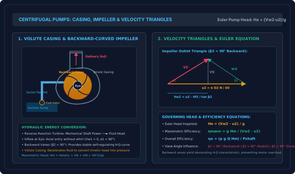
Figure 2: Multistage Hookups, Minimum Starting Speed & NPSH Hydraulic Gradient
This schematic details the head and discharge characteristics of multistage series vs parallel arrangements, the centrifugal forced-vortex shutoff head governing , and the hydraulic energy gradient defining and maximum allowable suction lift.
6. Comparative Engineering Analysis & Parameter Regimes
| Feature / Metric | Centrifugal Pump (Rotodynamic) | Reciprocating Pump (Positive Displacement) |
|---|---|---|
| Discharge Characteristic | Continuous, steady, non-pulsating flow | Pulsating, periodic flow (sinusoidal) |
| Head vs Discharge Relationship | Head decreases as discharge increases () | Discharge is strictly independent of delivery head |
| Operating Speed | High speed (), direct motor drive | Low speed (), requires reduction gears |
| Discharge Capacity | Medium to exceptionally large discharge | Low to moderate discharge |
| Delivery Pressure | Moderate per stage (); high via multistaging | Capable of extremely high pressures () |
| Priming Requirement | Mandatory prior to start (cannot pump air) | Self-priming (positive cylinder displacement) |
| Viscous Fluid Handling | Poor: efficiency drops severely with viscosity | Excellent: efficiently pumps oils, sludge, and pastes |
| Maintenance & Footprint | Compact, minimal moving parts, low maintenance | Bulky, heavy, numerous valves and packing seals |
| Specific Speed () | Medium to High: (radial to mixed flow) | Not applicable |
7. Worked Numerical Examples (Pre-Calculated & Verified)
Problem 1: Impeller Sizing, Velocity Triangles & Minimum Starting Speed
Problem Statement: A centrifugal pump is designed to deliver water against a static head with an impeller having an internal diameter and an external diameter . The width of the impeller is at inlet and at outlet. The pump runs at a synchronous speed .
The water enters the impeller eye radially without whirl (). The impeller vanes are curved backwards at an exit blade angle . Due to blade thickness, vanes occupy of the circumferential area (). The radial flow velocity is constant through the runner: . Efficiencies: Manometric efficiency , mechanical efficiency .
Calculate:
- Peripheral blade speeds at inlet () and outlet ().
- Total volumetric discharge in and .
- Inlet blade angle .
- Outlet whirl velocity , absolute exit velocity , and discharge angle .
- Euler head and actual manometric head .
- Water power and electric motor shaft input power in kW.
- The centrifugal forced-vortex shutoff head developed at , and the minimum starting speed required to initiate flow against a static head .
Step-by-Step Solution:
1. Peripheral Blade Velocities:
2. Volumetric Discharge (): Net outlet flow area:
(Check at inlet: ).
3. Inlet Blade Angle (): Since water enters radially ():
4. Outlet Velocity Triangle:
Whirl velocity at outlet:
Absolute exit velocity:
Absolute exit flow angle:
5. Euler Head & Manometric Head: Euler head imparted by impeller:
Actual net manometric head:
6. Power Output and Motor Input: Useful water power:
Overall pump efficiency:
Shaft driving power required:
7. Minimum Starting Speed (): Centrifugal shutoff head generated at operating speed :
Minimum rotational speed to initiate discharge against static head :
(Since , the pump begins discharging reliably upon opening the delivery valve).
Problem 2: Multistage Centrifugal Mine Dewatering Pump
Problem Statement: An underground coal mine dewatering installation employs a 4-stage centrifugal pump to lift groundwater from a deep shaft sump against a static elevation difference . Piping system specifications:
- Suction pipe: Length , diameter ().
- Delivery pipe: Length , diameter ().
- Darcy friction factor for both lines: .
- Design discharge: ().
- Pump synchronous speed: .
- Overall efficiency of the pump: .
Calculate:
- Flow velocities and , and pipe friction losses and .
- Total manometric head developed by the 4-stage pump, and head per stage .
- Shaft input power required from the electric motor in kW.
- The specific speed per stage in standard SI units ().
Step-by-Step Solution:
1. Pipe Flow Velocities and Head Losses: Suction pipe:
Delivery pipe:
2. Total Manometric Head & Stage Head:
Manometric head generated by each of the identical stages:
3. Electric Motor Driving Power: Useful water power:
Shaft power required:
4. Specific Speed per Stage: Applying the standard SI pump specific speed relation ( in , in ):
(Confirms typical low-specific-speed radial flow multistage impeller design).
Problem 3: NPSH Analysis, Suction Lift Limit & Cavitation Inception
Problem Statement: A centrifugal water pump operates in a pumping station situated at an altitude where ambient atmospheric pressure is (). The water temperature is , at which saturation vapor pressure is ().
The pump manufacturer certifies that the Net Positive Suction Head Required at the design discharge () is . The suction pipe has a diameter (). Total suction line head losses (foot valve, strainer, pipe friction, and elbows) are estimated at . Water density .
Determine:
- Atmospheric pressure head and vapor pressure head in meters of water.
- The suction pipe velocity head .
- The absolute theoretical maximum permissible suction lift above the sump water level.
- If the pump is physically installed with its suction eye at above the sump water surface, calculate the Available Net Positive Suction Head () and determine whether the pump will cavitate.
- The available safety margin against cavitation.
Step-by-Step Solution:
1. Pressure Heads:
2. Suction Velocity Head:
3. Maximum Permissible Suction Lift (): At the threshold of cavitation, :
4. Available NPSH at Actual Installation ():
5. Cavitation Evaluation & Safety Margin: Comparing available NPSH with manufacturer required NPSH:
Safety margin:
Since by a positive margin of , the pump is completely safe from cavitation.
8. High-Yield Examination Traps & Ambiguities
- Specific Speed Exponent Ambiguity:
- Trap: Using for pump specific speed.
- Clarification:
- Turbine Specific Speed: ( in kW).
- Pump Specific Speed: ( in ).
- Radial Entry Assumption:
- Trap: Including in the Euler head formula.
- Rule: For virtually all centrifugal pumps, water enters the eye radially without whirl: . Thus , NOT .
- Manometric Head vs Static Head:
- Trap: Equating to .
- Correction: must include all friction losses and delivery discharge kinetic head:
- Minimum Starting Speed Formula Application:
- Trap: Confusing the head against which the pump starts with operating manometric head.
- Rule: At shutoff (), the pump develops forced-vortex centrifugal head . For pumping to commence, this must overcome the static delivery head: .
- NPSH Formulation Trap:
- Trap: Forgetting to subtract vapor pressure head or adding suction lift instead of subtracting it.
- Anchor: . Both suction lift and suction friction degrade the available suction margin.
9. Real-World Engineering Applications & Case Studies
- Municipal Water Supply & Deep Sump Lift Stations: High-capacity double-suction split-case centrifugal pumps (flow rates ) are the workhorses of urban water treatment and distribution plants. Double-suction impellers draw fluid from both sides, eliminating axial hydraulic thrust.
- Kaleshwaram Lift Irrigation Project (Telangana, India): The largest multi-stage lift irrigation scheme in the world, Kaleshwaram employs mammoth single-stage vertical centrifugal pumps delivering against heads exceeding , lifting water from the Godavari river across multi-tier reservoir cascades.
- Boiler Feed Multistage Pumps (Thermal Power Plants): Supercritical coal power stations employ 10-to-14 stage centrifugal pumps operating in series at speeds up to , developing discharge pressures exceeding ( of water head) to inject feedwater into high-pressure steam boilers.
10. Cross-Disciplinary & Downstream Dependencies
                     ┌──────────────────────────────────────────┐
                     │ FM-08-01: Impact of Free Jets &          │
                     │ Euler Velocity Triangle Fundamentals     │
                     └────────────────────┬─────────────────────┘
                                          │
                                          ▼
┌────────────────────────────────────────────────────────────────────────────────────────┐
│ FM-08-04: CENTRIFUGAL PUMPS (MANOMETRIC HEAD, MIN SPEED, MULTISTAGE, NPSH & CAVITATION)│
└───────────┬─────────────────────────────┬───────────────────────────────┬──────────────┘
            │                             │                               │
            ▼                             ▼                               ▼
┌───────────────────────┐   ┌───────────────────────────┐   ┌────────────────────────────┐
│ FM-08-05: Recipro-    │   │ Environmental Engineering:│   │ Water Supply Network       │
│ cating Pumps & Air    │   │ Pumping Station Design,   │   │ Analysis: Hardy Cross &    │
│ Vessels Comparison    │   │ Intake Wells & Sumps      │   │ Pump Operating Point       │
└───────────────────────┘   └───────────────────────────┘   └────────────────────────────┘
- Upstream: Directly mirrors and reverses the inward-flow Euler momentum exchange from Francis reaction turbines (
FM-08-03). - Downstream Displacement Pumps: Provides the rotodynamic performance baseline against which reciprocating positive displacement pumps (
FM-08-05) are compared. - Downstream Civil Engineering: Fundamental to water supply engineering (intake wells, suction sumps, booster stations) and irrigation canal lift networks.
11. Summary Formula Cheat Sheet & Memory Anchors
- Inlet Triangle (Radial Entry):
- Outlet Whirl Velocity:
- Euler Pump Head:
- Manometric Head:
- Manometric Efficiency:
- Overall Efficiency:
- Minimum Starting Speed:
- Centrifugal Shutoff Head:
- Pumps in Series: (High Head)
- Pumps in Parallel: (High Discharge)
- Available NPSH:
- Max Suction Lift:
- Pump Specific Speed (SI):
12. Comprehensive References & Standard Codes
- Modi, P. N., & Seth, S. M. (2020). Hydraulics and Fluid Mechanics Including Hydraulics Machines (22nd ed.). Standard Book House, New Delhi.
- Karassik, I. J., Messina, J. P., Cooper, P., & Heald, C. C. (2008). Pump Handbook (4th ed.). McGraw-Hill Education, New York.
- Rajput, R. K. (2018). A Textbook of Fluid Mechanics and Hydraulic Machines (6th ed.). S. Chand & Company Ltd., New Delhi.
- IS 1520: 1980 — Horizontal Centrifugal Pumps for Clear, Cold, Fresh Water. Bureau of Indian Standards, New Delhi.
- IS 9137: 1978 — Code for Acceptance Tests for Centrifugal, Mixed Flow and Axial Pumps — Class C. Bureau of Indian Standards, New Delhi.
- HI 9.6.1: 2017 — Rotodynamic Pumps Guideline for NPSH Margin. Hydraulic Institute, Parsippany, NJ.