Pascal's Law, Hydrostatic Pressure Law & Manometry
In this chapter (4 topics)
On this page
- 1. Topic Metadata & Syllabus Mapping
- 2. Executive Summary & Core Engineering Concepts
- 3. Fundamental Governing Principles & Pascal's Law
- 3.1 Mathematical Proof of Pascal's Law
- 3.2 State of Stress & Mohr's Circle in Fluid Statics
- 3.3 Engineering Application: The Hydraulic Press / Jack
- 4. Hydrostatic Law & Vertical Pressure Variations
- 4.1 Derivation of the Hydrostatic Law
- 4.2 Absolute, Gauge, and Vacuum Pressures
- 4.3 Hydrostatic Paradox
- 5. Manometry Instrumentation & Working Principles
- 5.1 Piezometer Tube
- 5.2 Simple U-Tube Manometer
- 5.3 Differential U-Tube Manometer
- 5.4 Inverted U-Tube Manometer
- 5.5 Inclined Tube Micromanometer
- 6. Complete Mathematical Formulations & Derivations
- Summary Formula Reference
- 7. Visual Architectural Diagrams
- Diagram 1: Pascal's Law Wedge Element & Hydrostatic Pressure Distribution
- Diagram 2: Comprehensive Manometric Systems
- 8. Worked Numerical Problems
- Problem 1: Hydraulic Jack Mechanical Advantage & Elevation Offset (GATE / ESE Standard)
- Problem 2: Differential U-Tube Manometer Connecting Two Elevated Pipes (ESE / SSC JE Standard)
- Problem 3: Inverted U-Tube Differential Manometer for Flowmeter Head Loss (GATE Standard)
- 9. Common Traps, Fallacies & Edge Cases
- Trap 1: The Discontinuous Datum Error
- Trap 2: Neglecting the Sign Direction in Manometers
- Trap 3: Capillary Meniscus Errors in Narrow Tubes
- Trap 4: Confusing Gauge Pressure with Absolute Pressure in Barometric Wells
- Trap 5: Compressibility Effects in Tall Gas Columns
- 10. Multi-Exam Multi-Choice & Conventional Practice Set
- Q1. GATE CE (1 Mark) — Fluid Statics Mohr's Circle
- Q2. UPSC ESE (Paper-II) — Inclined Micromanometer Sensitivity
- Q3. SSC JE — Hydrostatic Pressure Head Conversion
- Q4. State AE — Mercury Barometer Elevation Correction
- Q5. RRB JE — U-Tube Differential Manometer Head Deflection
- 11. Cross-Subject Synthesis & Practical Field Applications
- 1. Geotechnical Engineering: Effective Stress Principle
- 2. Water Supply & Pipe Distribution Networks
- 3. Structural Design of Gravity Dams
- 12. Comprehensive Summary & Formula Cheatsheet
- Quick Revision Cards
- References & Standard Codes
1. Topic Metadata & Syllabus Mapping
| Field | Description / Value |
|---|---|
| Topic ID | FM-02-01 |
| Module Title | Pascal's Law, Hydrostatic Pressure Law & Manometry Systems |
| Primary Subject | Fluid Mechanics & Hydraulic Machinery |
| Parent Chapter | Chapter 02: Fluid Statics & Manometry |
| GATE CE Mapping | Fluid Statics: Fluid pressure, Pascal's law, hydrostatic law, pressure measurement using manometers (piezometer, U-tube, differential, inclined). |
| UPSC ESE Mapping | Paper-II Fluid Mechanics: Pressure at a point, Pascal's principle, variation of pressure in static fluids, absolute and gauge pressure, manometric fluid selection, micromanometers. |
| SSC JE / RRB JE | Hydrostatic pressure, , U-tube manometers, hydraulic jack mechanical advantage, pressure units conversion (, , of water, of ). |
| Core Competencies | 1. Prove Pascal's Law from free-body equilibrium of a triangular wedge element. 2. Derive hydrostatic law and establish pressure prism profiles. 3. Master the continuous datum jump technique for complex multi-fluid manometers. 4. Calculate sensitivity amplification factors for inclined micromanometers. |
2. Executive Summary & Core Engineering Concepts
Fluid statics deals with fluids at rest relative to their container or undergoing uniform solid-body motion without shear stresses (). Because fluids cannot sustain shear deformation when static, every internal surface experiences only normal compressive forces. The intensity of this normal compressive force per unit surface area in the limit as area approaches zero defines the fluid pressure ().
Two fundamental laws govern fluid statics:
- Pascal's Law: The pressure at any point in a static fluid is identical in all directions (isotropic scalar field, ). Consequently, the Mohr's circle of stress for a fluid at rest collapses into a single point on the normal stress axis with and .
- Hydrostatic Law: The rate of increase of pressure in a vertically downward direction is equal to the specific weight of the fluid (, or , where is positive downward).
Engineering applications rely on manometers—devices that balance unknown fluid pressures against hydrostatic columns of reference fluids (such as water, mercury, or light oils). Accurate manometric calculations demand a rigorous application of the horizontal datum jump rule: two points at the same horizontal elevation within a continuous body of the same homogeneous static fluid must carry identical pressures.
3. Fundamental Governing Principles & Pascal's Law
3.1 Mathematical Proof of Pascal's Law
Consider an infinitesimal arbitrary right-triangular fluid wedge element of dimensions , , and inclined hypotenuse length with unit thickness perpendicular to the plane, residing inside a static fluid mass of uniform density .
         z ^
           |        /|
           |       / |
           |   ds /  | dz
           |     / θ |
           |    /____|
           |      dx
           +------------------> x
From geometry:
The element is acted upon by:
- Normal pressure force on vertical face (): acting along .
- Normal pressure force on horizontal base face (): acting along .
- Normal pressure force on inclined surface (): directed inward perpendicular to .
- Self-weight of the fluid wedge acting vertically downward:
Applying the equations of static equilibrium ( and ):
Horizontal Equilibrium ():
Since :
Vertical Equilibrium ():
Since :
Dividing throughout by :
Taking the limit as the element shrinks to a point ():
Combining both equilibrium relations:
Because the orientation angle was chosen arbitrarily, the normal compressive pressure at any point in a static fluid is independent of direction. Pressure is a scalar quantity.
3.2 State of Stress & Mohr's Circle in Fluid Statics
In continuum mechanics, the stress tensor at a point in a static fluid is purely isotropic:
Where:
- Normal stresses are purely compressive: .
- Shear stresses are identically zero on all planes: .
- Mohr's Circle: Collapses to a single degenerate point on the -axis.
- The maximum shear stress .
3.3 Engineering Application: The Hydraulic Press / Jack
Pascal's principle implies that any externally applied pressure increment on an enclosed incompressible fluid is transmitted undiminished to every portion of the fluid and container walls.
In a hydraulic press having a plunger of cross-sectional area and a lifting ram of cross-sectional area :
The theoretical mechanical advantage () is:
By volume conservation for an incompressible fluid ():
Work done input equals work done output in an ideal lossless machine:
If the ram is positioned at a vertical distance relative to the plunger, the hydrostatic head of the hydraulic oil must be superimposed:
4. Hydrostatic Law & Vertical Pressure Variations
4.1 Derivation of the Hydrostatic Law
Consider a vertical cylindrical fluid element of cross-sectional area and height located at elevation above an arbitrary datum:
- Upward force on base at elevation :
- Downward force on top face at elevation :
- Downward gravity weight force:
                   ^ z
                   |       (p + dp) dA
                   |         | | |
                   |       +-------+
                   |       |  dW   |
                dz |       |   ↓   |
                   |       +-------+
                   |         ↑ ↑ ↑
                   |        p dA
                   +------------------>
For static equilibrium along the vertical axis ():
Dividing by :
Where:
- is the specific weight of the fluid ().
- The negative sign indicates that pressure decreases with increasing elevation .
If represents the vertical depth measured downwards from the free liquid surface ():
Integrating for an incompressible homogeneous fluid ():
Where:
- is the pressure acting on the free liquid surface (typically ).
- is the hydrostatic gauge pressure head.
4.2 Absolute, Gauge, and Vacuum Pressures
- Absolute Pressure (): Pressure measured relative to absolute zero pressure (a perfect vacuum, complete absence of molecular momentum exchange).
- Atmospheric Pressure (): Pressure exerted by the Earth's atmosphere. At standard sea level:
- Gauge Pressure (): Pressure measured above local atmospheric pressure:
- Vacuum Pressure (): Pressure measured below local atmospheric pressure (negative gauge pressure):
  Absolute Pressure Scale
  =======================
  ^
  |   p_abs = p_atm + p_gauge
  |   ----------------------- [Point A: Positive Gauge Pressure]
  |              ^
  |              | +p_gauge
  |              v
  |   ======================= [Local Atmospheric Pressure Level: p_atm]
  |              ^
  |              | p_vac (Negative Gauge)
  |              v
  |   ----------------------- [Point B: Sub-atmospheric / Vacuum]
  |   ^
  |   | p_abs
  |   v
  +-------------------------- [Absolute Zero Pressure / Perfect Vacuum]
4.3 Hydrostatic Paradox
The hydrostatic paradox states that:
The total normal force exerted by a static liquid on the bottom horizontal base of a vessel depends exclusively on the liquid density , the vertical depth , and the base surface area (). It is entirely independent of the shape of the container, the incline of the walls, or the total weight of the liquid contained.
   Container 1 (Vertical)    Container 2 (Flaring)     Container 3 (Tapering)
        |       |                 \           /                /       \
        |       |                  \         /                /         \
        |_______|                   \_______/                /___________\
        F_b = W_liq                 F_b < W_liq               F_b > W_liq
           Bottom Thrust F_b = ρ g h A is IDENTICAL for all three!
- In Container 2 (flaring walls), the inclined walls exert an upward reaction force component , supporting the excess fluid weight: .
- In Container 3 (tapering walls), the inclined walls exert a downward normal pressure component : .
- Equilibrium of the liquid mass as a free body satisfies vertical static equilibrium without contradiction.
5. Manometry Instrumentation & Working Principles
Manometers measure fluid pressure by balancing hydrostatic columns against known manometric liquids.
5.1 Piezometer Tube
A simple vertical transparent tube tapped into the pipe or container wall, open at the top to atmosphere.
- Gauge pressure:
- Limitations:
- Cannot measure negative / vacuum pressures (air would be sucked into the pipe).
- Cannot measure high pressures (requires impracticably tall glass columns).
- Cannot be used for gases (gas escapes into the atmosphere without forming a free surface).
- Capillarity effects introduce meniscus errors unless the internal tube diameter .
5.2 Simple U-Tube Manometer
Consists of a glass U-tube containing a heavy manometric fluid (typically mercury, ) that is immiscible with the pipe fluid.
Continuous Horizontal Datum Rule
Between any two points at the same horizontal elevation in a static continuous mass of the same fluid, the pressures must be equal ().
To write the manometric equation:
- Identify the lower interface meniscus between the pipe fluid and manometric fluid.
- Draw the reference datum line horizontally across both limbs passing through this lower meniscus.
- Equate pressure in the left limb to pressure in the right limb: In gauge pressure ():
5.3 Differential U-Tube Manometer
Measures the pressure difference between two points and in a pipeline or two separate pipelines.
Equating pressures at the lower meniscus datum line :
If both pipes carry the same liquid () and lie at the same elevation:
Expressed as an equivalent head of the flowing fluid :
5.4 Inverted U-Tube Manometer
Used for measuring very small differential pressures in liquids or where heavy fluids cannot be tolerated. The top bend contains a lighter manometric liquid (such as kerosene, ) or compressed air.
Because moving upward in a fluid column decreases pressure:
For pipes carrying water at the same elevation ():
Differential head of water:
When (e.g., ), the divisor , meaning the manometer deflection is 10 times magnified, providing extreme sensitivity for tiny head losses.
5.5 Inclined Tube Micromanometer
Consists of an enlarged reservoir of cross-sectional area connected to a narrow tube of cross-sectional area inclined at an angle to the horizontal.
When differential pressure is applied:
- The liquid level in the reservoir drops by .
- The liquid column in the inclined limb advances by length along the incline.
By volume conservation:
The vertical head difference between the two menisci is:
When the reservoir is very large relative to the tube (, such that ):
Sensitivity Gain:
For For
6. Complete Mathematical Formulations & Derivations
Summary Formula Reference
| Device / Principle | Governing Equation | Primary Variables & Units |
|---|---|---|
| Pascal's Law | : Fluid static pressure () | |
| Hydraulic Press | : Ram & plunger diameters () | |
| Hydrostatic Law | : Fluid density (), : Depth () | |
| Simple U-Tube | : Manometric & pipe fluid densities | |
| Differential U-Tube | : Mercury differential deflection () | |
| Identical Fluid Diff. Head | : Specific gravities of mercury & pipe fluid | |
| Inverted U-Tube (Same Level) | , light manometric fluid | |
| Inverted Diff. Head | : Oil meniscus difference () | |
| Inclined Micromanometer | : Travel length along tube, : Incline angle |
7. Visual Architectural Diagrams
Diagram 1: Pascal's Law Wedge Element & Hydrostatic Pressure Distribution
The following diagram details the free-body equilibrium of the triangular fluid element proving Pascal's Law, along with the hydrostatic pressure prism and paradox:
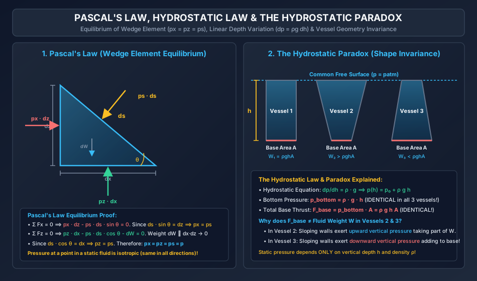
Diagram 2: Comprehensive Manometric Systems
The following diagram illustrates simple U-tubes (gauge and vacuum), differential U-tubes connecting two pipes, inverted light-fluid U-tubes, and inclined micromanometers:

8. Worked Numerical Problems
Problem 1: Hydraulic Jack Mechanical Advantage & Elevation Offset (GATE / ESE Standard)
Statement: A hydraulic jack is used to lift a heavy vehicle. The diameter of the small plunger is and the diameter of the large ram is . A downward force of is applied to the plunger. Take .
- Determine the load lifted by the ram when the ram and plunger cross-sections are at the exact same elevation.
- Determine the load lifted by the ram when the ram is located lower than the plunger, and the system is filled with hydraulic oil of specific gravity ().
- If the plunger stroke length is , determine the displacement of the ram per stroke, and verify conservation of energy.
Solution:
Part 1: Same Elevation
- Cross-sectional area of plunger:
- Cross-sectional area of ram:
- Pressure developed by plunger force:
- Load supported by ram: Alternative check:
Part 2: Ram Lower than Plunger
- Because the ram is lower, the hydrostatic pressure head of the oil increases the pressure at the ram face:
- Total pressure acting on the underside of the ram:
- Total load supported by ram: The oil column contributes an additional lifting force of:
Part 3: Ram Displacement & Energy Check
- By incompressible fluid volume displacement:
- Work done by effort force:
- Work done on load (at same elevation):
Problem 2: Differential U-Tube Manometer Connecting Two Elevated Pipes (ESE / SSC JE Standard)
Statement: A differential U-tube mercury manometer connects two pressurized pipelines and . Pipeline carries fuel oil of specific gravity () and its centerline is at datum elevation . Pipeline carries water (, ) and its centerline is at elevation . The manometer contains mercury of specific gravity (). The mercury meniscus in the left limb (connected to pipe ) is at a vertical depth of below the center of pipe . The mercury level in the right limb is higher than the left limb by a deflection of . Take .
- Calculate the pressure difference between the two pipes () in .
- Express this pressure difference as an equivalent head of water in meters.
Solution:
Geometry and Meniscus Elevations:
- Take the center of Pipe as reference elevation .
- Elevation of left limb mercury meniscus:
- Choose horizontal datum plane passing through this lowest continuous mercury meniscus at .
- Elevation of right limb mercury meniscus:
- Elevation of Pipe centerline:
- Vertical height of water column in right limb above the right mercury meniscus:
Hydrostatic Balance Across Datum :
- Pressure in left limb at datum :
- Pressure in right limb at datum :
- Equating :
Numerical Substitution:
- Water column head:
- Mercury column head:
- Oil column head:
Combining:
Part 2: Equivalent Head of Water:
Problem 3: Inverted U-Tube Differential Manometer for Flowmeter Head Loss (GATE Standard)
Statement: An inverted U-tube differential manometer is connected across a horizontal venturimeter throat and inlet carrying water (). The two connection points (inlet) and (throat) are at the identical horizontal centerline elevation (). The manometric fluid in the upper inverted bend is an oil of specific gravity (). The water meniscus in the right limb (connected to throat ) is observed at height below the crest. The water meniscus in the left limb (connected to inlet ) is at height below the crest. The differential oil column height between the two limbs is . Take .
- Compute the differential pressure between the inlet and throat in .
- Express the differential head in of water column.
Solution:
Hydrostatic Form for Inverted Manometers: In an inverted manometer, moving upward through fluid columns reduces the hydrostatic pressure. Let the water surface in limb be at height and limb at height . Since , the higher pressure at drives the water column higher into the inverted loop:
- Left limb: Water extends up to height from the pipe axis.
- Right limb: Water extends up to height from the pipe axis.
- Oil column of height occupies the limb between the two water menisci.
Tracing pressures from to via the top loop:
Moving across the oil column to the right meniscus at lower height :
Moving down the right limb water column back to pipe :
Rearranging for differential pressure:
Numerical Substitution:
Part 2: Differential Head in mm of Water:
Sensitivity Analysis: Notice that an actual pressure head difference of only of water produced a massive physical manometer deflection of !
This demonstrates why inverted manometers with light oils () are chosen for measuring small venturi and orifice head losses.
9. Common Traps, Fallacies & Edge Cases
Trap 1: The Discontinuous Datum Error
- The Fallacy: Drawing a horizontal datum line across two limbs through arbitrary points without verifying that the fluid between those points is continuous and homogeneous.
- The Physical Reality: at horizontal elevation holds only if one can trace a continuous, unbroken path between 1 and 2 entirely through the same homogeneous fluid at rest. Jumping across an interface or across two different fluid bodies violates static equilibrium.
Trap 2: Neglecting the Sign Direction in Manometers
- The Fallacy: Adding heads when moving upward, or subtracting when moving downward.
- The Golden Rule:
- Moving DOWNWARD through a fluid column: ADD pressure ().
- Moving UPWARD through a fluid column: SUBTRACT pressure ().
Trap 3: Capillary Meniscus Errors in Narrow Tubes
- The Fallacy: Using narrow glass tubes () for piezometers and assuming the observed meniscus height directly equals hydrostatic pressure head.
- The Correction: Capillarity causes a meniscus rise () in water or capillary depression in mercury. To keep capillary head error under of water, manometer tube diameters must be at least . Alternatively, in differential U-tubes with uniform bores, the capillary rise in both identical limbs cancels out.
Trap 4: Confusing Gauge Pressure with Absolute Pressure in Barometric Wells
- The Fallacy: Stating that the pressure at the closed top of a Torricellian mercury barometer is zero gauge.
- The Correction: The vapor space above the mercury column contains mercury vapor at vapor pressure ( at ). It is near absolute zero, meaning its gauge pressure is approximately .
Trap 5: Compressibility Effects in Tall Gas Columns
- The Fallacy: Applying with constant for tall gas columns (e.g., chimneys, mine shafts, atmospheric elevation changes ).
- The Correction: Gases are compressible (). For an isothermal column, pressure decreases exponentially:
10. Multi-Exam Multi-Choice & Conventional Practice Set
Q1. GATE CE (1 Mark) — Fluid Statics Mohr's Circle
Question: The state of stress at any point in a fluid at rest under gravity is characterized by which of the following statements?
- (A) Maximum shear stress equals hydrostatic pressure .
- (B) Mohr's circle of stress has a radius equal to centered at origin.
- (C) Mohr's circle collapses to a single point on the normal stress axis at .
- (D) Normal stress varies sinusoidally with plane inclination angle .
Solution: In a static fluid, shear stresses are identically zero on all planes (). By Pascal's law, normal compressive stresses are isotropic: . The radius of Mohr's circle is:
The circle collapses to a point at . Correct Answer: (C)
Q2. UPSC ESE (Paper-II) — Inclined Micromanometer Sensitivity
Question: An inclined manometer tube is inclined at an angle of to the horizontal. The reservoir area is times the cross-sectional area of the inclined tube (). The sensitivity amplification factor compared to a standard vertical tube manometer is:
- (A)
- (B)
- (C)
- (D)
Solution: The exact relation for the inclined tube manometer deflection under vertical head is:
The amplification factor (sensitivity gain) is:
(Note: If reservoir drop is neglected, . Accounting for reservoir drawdown yields .) Correct Answer: (D)
Q3. SSC JE — Hydrostatic Pressure Head Conversion
Question: An oil of specific gravity is under a gauge pressure of . The equivalent pressure head expressed in meters of oil and meters of water () are respectively:
- (A) of oil, of water
- (B) of oil, of water
- (C) of oil, of water
- (D) of oil, of water
Solution: Density of oil . Pressure head in oil:
Pressure head in water:
Correct Answer: (A)
Q4. State AE — Mercury Barometer Elevation Correction
Question: A mercury barometer reads of at the ground floor of a multi-story building. At the top roof of the building, the barometer reads of . Assuming an average air density of and specific gravity of mercury (), the height of the building is:
- (A)
- (B)
- (C)
- (D)
Solution: Pressure drop between ground floor and roof:
Canceling :
Correct Answer: (B)
Q5. RRB JE — U-Tube Differential Manometer Head Deflection
Question: In a differential U-tube manometer containing mercury (), water flows through two pipes at the same elevation. If the mercury deflection between the limbs is , the differential head in meters of water is:
- (A)
- (B)
- (C)
- (D)
Solution: For identical fluids at the same elevation:
Correct Answer: (B)
11. Cross-Subject Synthesis & Practical Field Applications
1. Geotechnical Engineering: Effective Stress Principle
In soil mechanics, Terzaghi's effective stress principle states:
Where is the pore water pressure. Below the phreatic groundwater table at depth , the pore water is static and follows the hydrostatic law:
If artesian pressure or upward hydraulic seepage exists, the pore pressure deviates from hydrostatic, directly reducing and triggering soil liquefaction or quicksand failure ().
2. Water Supply & Pipe Distribution Networks
Hydraulic gradient lines (HGL) and Energy gradient lines (EGL) in municipal distribution networks are direct manifestations of piezometric head:
Piezometric head governs pipe bursting limits, cavitation thresholds at pipeline summits, and minimum residual pressure standards () for fire-fighting hydrants.
3. Structural Design of Gravity Dams
Hydrostatic pressure against the upstream face of concrete gravity dams produces a triangular horizontal thrust prism with maximum base intensity . Foundation drainage galleries bleed internal water to relieve uplift pressure profiles that threaten overturning and base sliding stability.
12. Comprehensive Summary & Formula Cheatsheet
Quick Revision Cards
================================================================================
                    FLUID STATICS & MANOMETRY CHEATSHEET
================================================================================

1. PASCAL'S LAW:
   - p_x = p_y = p_z = p  (Normal stress is isotropic in static fluids)
   - Mohr's Circle collapses to single point (-p, 0); τ_max = 0

2. HYDROSTATIC LAW:
   - dp/dz = -ρ g = -γ   (Downward: dp/dh = +ρ g)
   - p(h) = p_0 + ρ g h  (Linear triangular pressure distribution)
   - Hydrostatic Paradox: Bottom thrust F = ρ g h A depends ONLY on h, ρ, A

3. PRESSURE CONVERSIONS:
   - p_abs = p_atm + p_gauge
   - p_vac = p_atm - p_abs = -p_gauge
   - 1 atm = 101.325 kPa = 1.01325 bar = 760 mm Hg = 10.33 m H2O

4. MANOMETRIC JUMP RULES:
   - Rule 1: Moving DOWN adds pressure (+ρ g h)
   - Rule 2: Moving UP subtracts pressure (-ρ g h)
   - Rule 3: Points on same horizontal level in CONTINUOUS SAME fluid have p_L = p_R

5. DIFFERENTIAL MANOMETERS:
   - Heavy Fluid (Mercury, pipes at same level):
     h_diff = h_m (S_m / S - 1)  --> For water: h_w = 12.6 h_m
   - Inverted Light Fluid (Oil S < 1, pipes at same level):
     h_diff = h_oil (1 - S_oil / S_w)  --> Magnified deflection!

6. INCLINED MICROMANOMETER:
   - Δp = ρ g L (sin θ + a/A) ≈ ρ g L sin θ
   - Sensitivity Gain = 1 / sin θ  (For θ = 30° -> 2.0x; θ = 5.74° -> 10.0x)
================================================================================
References & Standard Codes
- Streeter, V. L., Wylie, E. B., and Bedford, K. W., Fluid Mechanics, 9th Edition, McGraw-Hill, New York.
- White, F. M., Fluid Mechanics, 8th Edition, McGraw-Hill Education, 2016.
- Modi, P. N., and Seth, S. M., Hydraulics and Fluid Mechanics Including Hydraulics Machines, Standard Book House, New Delhi.
- Fox, R. W., McDonald, A. T., and Pritchard, P. J., Introduction to Fluid Mechanics, 8th Edition, John Wiley & Sons.
- IS 4984:1995, High Density Polyethylene Pipes for Water Supply - Specification, Bureau of Indian Standards.