Pelton Wheel Impulse Turbines: Hydraulic Layout, Velocity Triangles, Bucket Mechanics, Efficiencies & Governing
In this chapter (5 topics)
On this page
- 1. Module Overview & Pedagogical Scope
- 2. Official Examination Syllabus Mapping
- 3. Fundamental Physical Principles & Governing Assumptions
- 4. Mathematical Derivations & Rigorous Proofs
- Sub-derivation A: Net Available Head & Jet Velocity
- Sub-derivation B: Bucket Kinematics & Velocity Triangles
- Sub-derivation C: Work Done, Runner Power & Hydraulic Efficiency
- Sub-derivation D: Empirical Design Proportions & Standard Sizing (IS 12800)
- Sub-derivation E: Governing Mechanics & Hydraulic Transient Protection
- 5. Technical Diagrams & Interactive Architectural Schematics
- Figure 1: Pelton Wheel Hydroelectric Plant Layout & Spear Nozzle Governing
- Figure 2: Double-Hemispherical Bucket Mechanics & Combined Velocity Triangles
- 6. Comparative Engineering Analysis & Parameter Regimes
- 7. Worked Numerical Examples (Pre-Calculated & Verified)
- Problem 1: Complete Pelton Wheel Design & Sizing
- Problem 2: Velocity Triangles & Runner Efficiency with Friction
- Problem 3: Sudden Full-Load Trip, Deflector Action & Breaking Jet Dynamics
- 8. High-Yield Examination Traps & Ambiguities
- 9. Real-World Engineering Applications & Case Studies
- 10. Cross-Disciplinary & Downstream Dependencies
- 11. Summary Formula Cheat Sheet & Memory Anchors
- 12. Comprehensive References & Standard Codes
1. Module Overview & Pedagogical Scope
The Pelton wheel (patented by Lester Allan Pelton in 1880) is the premier tangential flow, free-jet impulse hydraulic turbine. It is universally deployed in hydroelectric power installations operating under high heads (typically , extending upwards of ) with comparatively low volumetric discharge rates ().
In an impulse turbine, the entire available hydraulic potential head of the reservoir is converted into kinetic energy inside stationary converging needle nozzles prior to entering the runner. The high-velocity free water jet emerges into an ambient atmospheric casing and impinges tangentially upon a circular array of contoured, double-hemispherical split buckets mounted on the periphery of the rotor wheel.
                  Pelton Hydroelectric Energy Conversion
    ┌───────────────────────────┐         High Pressure Head H
    │ High-Head Storage Dam     │───────────────────────────────────┐
    └───────────────────────────┘                                   │
                                                                    ▼
                                                            ┌───────────────┐
                                                            │ Penstock Pipe │
                                                            └───────┬───────┘
                                                                    │
                                                                    ▼
    ┌───────────────────────────┐         Free Jet V1       ┌───────────────┐
    │ Pelton Runner Wheel       │◄──────────────────────────┤ Spear Nozzle  │
    │ Rotating at N (rpm)       │  100% Kinetic Head        │ Converging Cv │
    └─────────────┬─────────────┘                           └───────────────┘
                  │ Torque T = ṁ ΔVw R
                  ▼
    ┌───────────────────────────┐
    │ Synchronous AC Generator  │───► Electrical Power Grid (P = ηo ρ g Q H)
    └───────────────────────────┘
This master technical module presents the comprehensive fluid dynamics, mechanical design proportions, velocity triangle kinematics, efficiency formulations, and governing control systems of the Pelton impulse turbine:
- Complete layout of high-head installations (penstocks, surge tanks, spear nozzles, casings, and tailrace clearance).
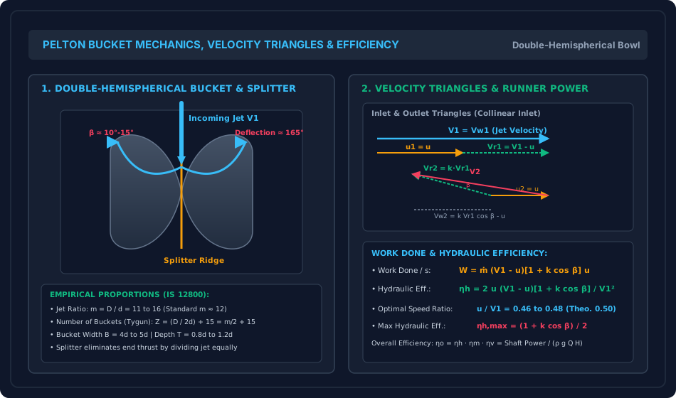
- Kinematics of double-hemispherical buckets and the role of the central splitter ridge in balancing axial end-thrust.
- Rigorous derivation of Euler's turbine work equation, whirl velocity components (), and hydraulic runner efficiency () accounting for bucket surface friction ().
- Empirical design ratios standardized by IS 12800 (jet ratio , Tygun's formula for bucket count , bucket dimensions ).
- Dynamic governing via spear needle throttling, jet deflector servomechanisms for water hammer mitigation, and auxiliary breaking jets.
2. Official Examination Syllabus Mapping
Website note: this mapping is from the author’s notes. It has not been checked against the official notification for each examination; confirm the current syllabus with the examining body.
| Examination Body | Syllabus Code & Topics | Core Weightage & Target Focus |
|---|---|---|
| GATE (Civil Engineering) | Water Resources: Hydraulic Machinery — Pelton wheel impulse turbines; Velocity triangles; Work done and power developed; Hydraulic, mechanical, and overall efficiencies; Design parameters (jet ratio, speed ratio, bucket count); Specific speed. | Very High (Guaranteed Questions): Calculation of runner diameter, jet diameter, velocity triangles, runner power, and efficiency optimization. |
| UPSC ESE (Prelims & Mains) | Paper-II: Fluid Mechanics and Hydraulic Machines — Classification of turbines, impulse vs reaction, Pelton wheel component details, velocity triangles, work done, efficiencies, governing of Pelton turbine (deflector and spear), cavitation and setting. | Core Subject: Derivation of , numerical design of multi-jet Pelton units, and governor mechanics. |
| SSC JE & RRB JE | Civil / Mechanical Engineering — Impulse turbines, Pelton wheel components, function of casing, draft tube absence, speed ratio range, formula for bucket count. | Direct / Objective: Value ranges (, , ), casing role (prevent splashing, no pressure). |
| State AE / JE (All States) | Fluid Mechanics & Machinery — Hydroelectric plant layout, Pelton turbine head and efficiency, work done per second per unit weight, spear valve operation. | Objective & Numerical: Numerical sizing of jets, pitch diameter, runner power, and water power. |
3. Fundamental Physical Principles & Governing Assumptions
- Pure Impulse Operation: The pressure throughout the runner casing is strictly uniform and equal to atmospheric pressure (). No pressure drop occurs across the buckets ().
- Complete Potential-to-Kinetic Conversion: All head conversion from pressure energy to kinetic energy occurs entirely within the stationary spear nozzle.
- No Draft Tube Required: Because the turbine operates at atmospheric pressure, the runner must be set with positive vertical clearance strictly above the maximum tailrace flood level. No draft tube is installed (a draft tube would drown the runner and destroy the free jet).
- Casing Has No Hydraulic Function: The outer casing merely prevents water from splashing onto the surroundings and guides discharged water into the tailrace channel.
- Collinear Inlet Velocity Triangle: The nozzle directs the jet tangentially along the pitch circle of the runner. Therefore, the absolute approach velocity , the blade peripheral velocity , and the relative velocity are strictly parallel and collinear at inlet ().
- Symmetrical Jet Splitting: The central splitter ridge divides the incoming cylindrical jet into two equal, symmetrical sheets that deflect sideways by angle , perfectly canceling out lateral axial thrust forces on the wheel shaft ().
4. Mathematical Derivations & Rigorous Proofs
========================================================================================
PELTON WHEEL HYDRODYNAMIC DERIVATION MAP
========================================================================================
Gross Head Hg & Net Head H = Hg - hf
       │
       ▼
Converging Spear Nozzle (Cv ≈ 0.98 - 0.99)
Jet Velocity: V1 = Cv √(2gH)
       │
       ▼
Collinear Inlet: u = πDN/60 = Ku √(2gH)
Relative Velocity at Inlet: Vr1 = V1 - u (Vw1 = V1, Vf1 = 0)
       │
       ▼
Bucket Flow with Wall Friction (k = Vr2 / Vr1 ≈ 0.85 - 0.95)
Relative Velocity at Exit: Vr2 = k Vr1 = k (V1 - u)
Exit Whirl Velocity: Vw2 = Vr2 cos β - u = k (V1 - u) cos β - u
       │
       ▼
Euler Momentum Exchange: ΔVw = Vw1 - (-Vw2) = (V1 - u)[1 + k cos β]
       │
       ├─────────────────────────────────────────┐
       ▼                                         ▼
Runner Driving Force & Power              Hydraulic Efficiency
Fx = ṁ (V1 - u)[1 + k cos β]             ηh = 2u(V1 - u)[1 + k cos β] / V1²
P = ṁ (V1 - u)[1 + k cos β] u             Optimal: u/V1 = 0.50 (Theo) | 0.46 (Actual)
                                          ηh,max = (1 + k cos β) / 2
========================================================================================
Sub-derivation A: Net Available Head & Jet Velocity
Let be the gross static head between the upstream reservoir water surface and the centerline of the nozzle. The water flows through a long penstock of length , diameter , and Darcy friction factor .
The head lost to pipe friction in the penstock is given by Darcy-Weisbach:
The net effective head available at the nozzle inlet is:
Inside the nozzle, the fluid accelerates through a converging passage. By Bernoulli's equation between the penstock base and the nozzle tip:
Accounting for nozzle viscous friction via the coefficient of velocity ():
The volumetric discharge from a single nozzle of diameter is:
If the turbine features identical nozzles (multi-jet Pelton wheel), total plant discharge is:
Sub-derivation B: Bucket Kinematics & Velocity Triangles
Let:
- : Pitch diameter (mean runner diameter measured at the centerline of the striking jet).
- : Rotational speed of the runner in revolutions per minute (rpm).
- : Tangential peripheral velocity of the buckets at pitch radius .
1. Inlet Velocity Triangle:
Because the free jet impinges tangentially along the pitch line:
- Guide vane / nozzle angle:
- Blade inlet angle:
Therefore, the velocity triangle at inlet collapses into a single horizontal straight line:
The relative velocity at inlet is simply the algebraic difference:
2. Outlet Velocity Triangle:
The double-hemispherical bucket splits the jet into two equal streams. As the fluid glides along the polished curved bowl, it is deflected through an angle , where is the blade exit tip angle (typically ).
Due to fluid boundary layer shear along the wetted bucket surface, relative velocity decreases slightly:
(For an idealized frictionless bucket, . In practical installations, .)
Resolving relative velocity at exit:
- The component of tangential to the wheel pointing backwards (opposite to blade motion) is .
- The transverse component pointing sideways is (which is canceled by the identical symmetrical opposite bowl).
The absolute velocity vector at exit is the vector sum: .
Projecting along the tangential direction of motion gives the exit whirl velocity :
Because is directed backwards while is directed forwards, the vector change in whirl velocity across the bucket is:
Sub-derivation C: Work Done, Runner Power & Hydraulic Efficiency
1. Dynamic Thrust Exerted on the Wheel:
Because a continuous series of buckets revolves through the jet trajectory, the entire mass discharged by the nozzle(s) per second is intercepted without mass deficit:
Applying Euler's momentum equation in the tangential direction:
2. Work Done per Second (Runner Power ):
Work done per unit weight of water supplied:
3. Hydraulic Efficiency ():
The hydraulic efficiency relates the mechanical power extracted by the runner to the total kinetic energy supplied by the jet:
4. Condition for Maximum Hydraulic Efficiency:
To maximize for a given jet velocity and blade angle , differentiate with respect to blade speed :
Substituting into the efficiency equation:
Theoretical Maximum Limits:
- If buckets are frictionless () and semicircular (, deflection ):
- In practical engineering designs, is set between (to prevent exiting water from striking the back of the advancing bucket) and , yielding:
- Due to minor windage and bearing resistance, actual commercial turbines run at an optimal speed ratio slightly below :
Sub-derivation D: Empirical Design Proportions & Standard Sizing (IS 12800)
- Speed Ratio ( or ):
- Velocity Coefficient of Nozzle ():
- Jet Ratio ():
The ratio of the pitch diameter of the runner wheel to the diameter of the jet :
- Standard range: (Optimal for high efficiency).
- If , buckets crowd together and interfere with incoming jets.
- If , the turbine wheel becomes excessively large, heavy, and costly.
- Number of Buckets on Runner (): To prevent water from escaping unintercepted between successive buckets while avoiding excessive frictional wetted area, the bucket count is determined by Tygun's empirical formula: (For , buckets; for , buckets.)
- Bucket Dimensions (in terms of jet diameter ):
- Bucket Width (): (to contain jet spread).
- Bucket Length (): .
- Bucket Depth (): .
- Splitter Notch Cutout (): (allows the bucket to enter the jet without clipping).
- Number of Jets ():
- For a horizontal shaft Pelton turbine, jets.
- For a vertical shaft Pelton turbine, up to jets spaced symmetrically around the wheel perimeter are employed.
Sub-derivation E: Governing Mechanics & Hydraulic Transient Protection
                                Governor Control Loop
    Grid Frequency / Speed Drop
               │
               ▼
     Centrifugal Governor / Digital ECU
               │
               ├─────────────────────────────────────────┐
               ▼ (Fast Action: ~0.2 - 0.5 s)             ▼ (Slow Action: ~20 - 40 s)
     Jet Deflector Servomotor                  Spear Needle Servomotor
     Pivots plate directly into jet            Retracts needle gradually
     Diverts water away from buckets           Prevents Penstock Water Hammer
When an electrical generator connected to a Pelton turbine undergoes sudden load rejection (breaker trips open), the resistant electrical torque drops instantly to zero. If the high-pressure water stream continues impinging on the buckets, the wheel will rapidly accelerate towards its runaway speed (), destroying generator windings via centrifugal stress.
However, the penstock water column possesses immense linear momentum (). If the needle nozzle were snapped shut in , a catastrophic Joukowsky water hammer pressure surge () would rupture the penstock.
The Combined Deflector-Spear Solution:
- Jet Deflector Action (Immediate): Within , an oil-pressure servomotor drives a curved deflector plate into the path of the jet, slicing the stream and directing it safely into the tailrace casing without changing the discharge rate . Rotor acceleration is arrested immediately.
- Spear Needle Throttling (Slow): The spear needle then closes at a controlled, leisurely rate over , keeping the Allievi pressure rise in the penstock below of static head.
- Breaking Jet: During scheduled plant shutdown, when the spear needle is completely closed, the massive runner (with flywheel effect ) would continue coasting on low-friction bearings for over . A small auxiliary nozzle directs a high-pressure breaking jet against the back of the buckets, producing a strong counter-torque that brings the runner safely to rest in .
5. Technical Diagrams & Interactive Architectural Schematics
Figure 1: Pelton Wheel Hydroelectric Plant Layout & Spear Nozzle Governing
This schematic illustrates the complete high-head hydroelectric installation from reservoir and penstock to the casing, spear nozzle, deflector plate, runner wheel, and tailrace clearance.
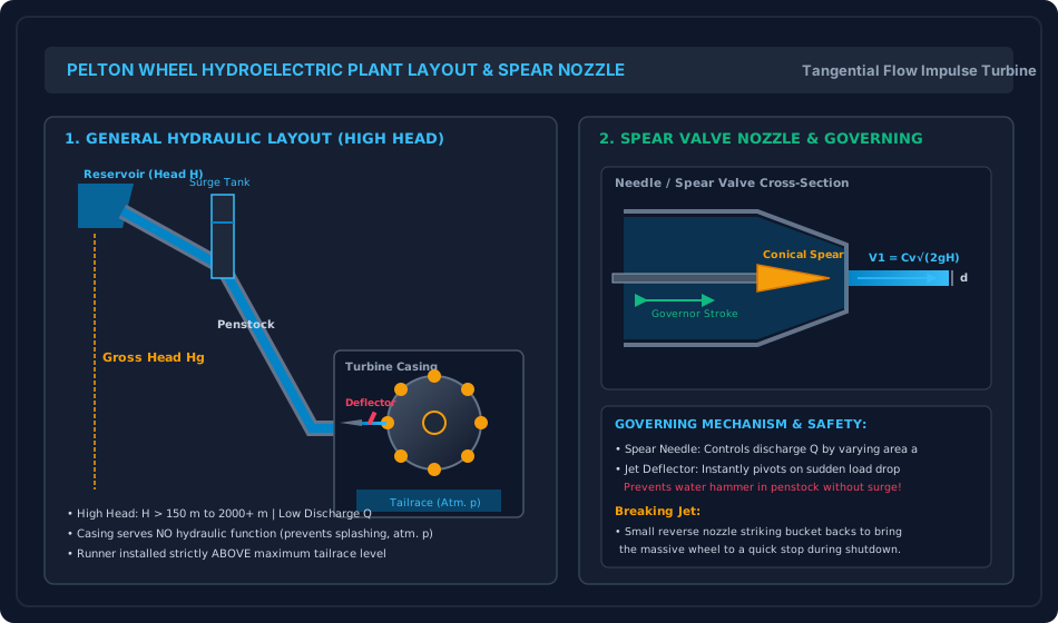
Figure 2: Double-Hemispherical Bucket Mechanics & Combined Velocity Triangles
This schematic details the geometry of the double-hemispherical bucket, the central splitter ridge dividing the jet into two symmetrical sheets, the collinear inlet triangle, and the outlet velocity triangle governing Euler head and runner efficiency.
6. Comparative Engineering Analysis & Parameter Regimes
| Engineering Parameter | Pelton Wheel (Impulse) | Francis Turbine (Reaction) | Kaplan Turbine (Reaction) |
|---|---|---|---|
| Head Regime () | High Head: | Medium Head: | Low Head: |
| Discharge Regime () | Low Discharge | Medium Discharge | Very High Discharge |
| Specific Speed ( in SI units) | Low: (Single Jet) Up to (Multi-Jet) |
Medium: | High: |
| Pressure Across Runner | Strictly atmospheric everywhere () | Continuous pressure drop () | Continuous pressure drop () |
| Flow Direction Through Runner | Tangential to pitch circle | Inward mixed (radial to axial) | Purely axial |
| Draft Tube Requirement | NO Draft Tube (Runner set above tailrace) | Mandatory Draft Tube (Pressure recovery) | Mandatory Draft Tube (Pressure recovery) |
| Casing Function | Prevents splashing; guides water to tailrace | Pressurized spiral scroll case converts head | Pressurized spiral scroll case converts head |
| Part-Load Efficiency Curve | Exceptionally Flat: High efficiency () down to rated load via spear throttling | Steep drop below rated load | Very flat (due to dual-regulated movable blades) |
7. Worked Numerical Examples (Pre-Calculated & Verified)
Problem 1: Complete Pelton Wheel Design & Sizing
Problem Statement: A hydroelectric power station utilizes a Pelton turbine operating under a net effective head of . The turbine develops a shaft power of () when revolving at a synchronous speed of .
The overall efficiency of the plant is , and the mechanical efficiency is . Design coefficients:
- Speed ratio:
- Nozzle velocity coefficient:
- Jet ratio:
- Water density:
Calculate:
- The absolute velocity of the jet and bucket peripheral velocity .
- The pitch diameter of the runner wheel.
- The total volumetric discharge required in and .
- The diameter of the jet .
- The discharge from a single jet , and the number of jets required.
- The number of buckets on the runner using Tygun's formula.
- The runner power and hydraulic efficiency .
Step-by-Step Solution:
1. Jet and Blade Velocities: Theoretical spouting velocity:
Absolute velocity of jet:
Peripheral bucket pitch velocity:
2. Pitch Diameter of the Runner Wheel ():
3. Total Volumetric Discharge (): Shaft power equation:
4. Jet Diameter (): Using the design jet ratio :
5. Single Jet Discharge () and Number of Jets (): Cross-sectional area of one jet:
Discharge from one jet:
Number of jets required:
6. Number of Buckets on Runner (): Applying Tygun's empirical formula:
7. Runner Power and Hydraulic Efficiency:
Hydraulic efficiency:
Problem 2: Velocity Triangles & Runner Efficiency with Friction
Problem Statement: A single-jet Pelton turbine operates under a net head . The nozzle diameter is () with velocity coefficient . The pitch diameter of the wheel is , and it runs at .
The buckets deflect the jet through an angle (so the exit blade angle is ). Due to bucket surface friction, the relative exit velocity is ().
Determine:
- The inlet jet velocity , bucket speed , and speed ratio .
- Relative velocities and .
- The exit whirl velocity , flow velocity , absolute exit velocity , and exit angle .
- The tangential driving force on the runner.
- The power developed by the runner in kW and MW.
- The hydraulic efficiency based on jet kinetic energy () and based on total head (), and compare with the theoretical maximum possible efficiency .
Step-by-Step Solution:
1. Kinematic Velocities:
Bucket speed:
Speed ratio:
2. Relative Velocities:
3. Outlet Triangle Components: Exit blade angle .
Exit whirl velocity pointing backwards relative to the wheel:
Absolute exit velocity:
Exit angle with tangential direction:
4. Discharge and Tangential Driving Force ():
Total change in whirl velocity across runner:
Tangential force:
5. Power Developed:
6. Efficiency Calculations: Total available water power at nozzle inlet:
Hydraulic efficiency of the turbine:
(Runner efficiency based on jet kinetic energy alone: . Note that .)
Maximum theoretical hydraulic efficiency:
(Achievable at optimal blade speed , corresponding to .)
Problem 3: Sudden Full-Load Trip, Deflector Action & Breaking Jet Dynamics
Problem Statement: A high-head hydroelectric installation has a Pelton turbine operating under a net head supplied by a steel penstock of length in which steady flow velocity is . The acoustic water-hammer pressure wave velocity in the penstock is . The rotating assembly (runner wheel + generator rotor) has a total polar moment of inertia and rotates at .
- Part A (Aeroelastic Deflector vs Spear Valve): When a sudden electrical fault trips the generator breaker, calculate the critical penstock closure time . If the spear needle were closed rapidly in , calculate the Joukowsky water hammer pressure rise . Compare this with the controlled slow closure over enabled by the jet deflector plate.
- Part B (Breaking Jet Sizing): After complete spear valve closure, the rotor continues coasting at (). An auxiliary breaking nozzle of diameter (, ) fed directly from the penstock () impinges normally on the back of the buckets at pitch radius . Assuming flat bucket back impact (), determine the braking thrust , retarding torque , angular deceleration , and the time taken to bring the unit to a complete stop.
Step-by-Step Solution:
Part A: Penstock Water Hammer Analysis:
- Critical closure time:
- If needle closed rapidly in (Rapid Joukowsky Closure):
- Controlled slow closure over (Allievi Slow Closure):
Engineering Takeaway: The jet deflector plate acts in to prevent overspeed runaway, allowing the spear valve to close slowly over , limiting the pressure surge from down to .
Part B: Breaking Jet Deceleration Dynamics:
- Initial rotational angular velocity:
- Breaking jet velocity and nozzle area:
- Breaking retarding force:
- Retarding braking torque at :
- Angular deceleration of the assembly:
- Time required to bring runner to complete rest:
(Without the breaking jet, bearing friction alone would take over 45 minutes to stop the spinning runner).
8. High-Yield Examination Traps & Ambiguities
- Draft Tube Absence Trap:
- Trap: Expecting a draft tube or calculating negative pressure at the Pelton runner exit.
- Rule: Pelton wheels never use a draft tube. The entire runner operates at atmospheric pressure (). Installing a draft tube would submerge the buckets in tailrace water, causing tremendous churning resistance and destroying efficiency.
- Casing Pressure Trap:
- Trap: Assuming the casing is under high hydraulic pressure like a Francis scroll case.
- Clarification: The Pelton casing is under zero gauge pressure (atmospheric). Its only functions are splash containment and structural safety.
- Speed Ratio Definition ( vs ):
- Trap: Defining instead of .
- Exact Form: By standard hydraulic convention, the speed ratio is (). The ratio is related by .
- Number of Buckets Formula:
- Trap: Confusing Tygun's formula with reaction turbine blade counts.
- Rule: Always use .
- Efficiency Definition: Runner vs Total Hydraulic:
- Trap: Equating runner efficiency based on jet energy () with overall hydraulic efficiency ().
- Connection: . Since , .
9. Real-World Engineering Applications & Case Studies
- Bhakra & Koyna Hydroelectric Projects (India): The Koyna Stage I & II underground powerhouse operates four vertical-shaft Pelton turbines under an effective net head of . Each runner utilizes 4 multi-jet nozzles spaced circumferentially at intervals to achieve high power density with compact runner diameters.
- Bieudron Hydroelectric Power Station (Switzerland): Holding the world record for the highest operating head on a single stage, the Bieudron plant features three massive 5-jet Pelton turbines operating under an astonishing net head of (), each generating of power at with jet velocities exceeding ().
- Pelton Bucket Erosion & HVOF Coating: High-velocity water jets carrying abrasive quartz silt particles inflict severe cavitation and silt erosion on bucket splitter ridges. Modern installations utilize Supermartensitic stainless steel (13Cr-4Ni) coated with High-Velocity Oxy-Fuel (HVOF) Tungsten Carbide (WC-Co-Cr) coatings to prolong runner service life.
10. Cross-Disciplinary & Downstream Dependencies
                     ┌──────────────────────────────────────────┐
                     │ FM-08-01: Impact of Free Jets &          │
                     │ Moving Curved Vane Momentum Balance      │
                     └────────────────────┬─────────────────────┘
                                          │
                                          ▼
┌────────────────────────────────────────────────────────────────────────────────────────┐
│ FM-08-02: PELTON WHEEL IMPULSE TURBINES (BUCKET MECHANICS, PROPORTIONS, GOVERNING)     │
└───────────┬─────────────────────────────┬───────────────────────────────┬──────────────┘
            │                             │                               │
            ▼                             ▼                               ▼
┌───────────────────────┐   ┌───────────────────────────┐   ┌────────────────────────────┐
│ FM-08-03: Francis &   │   │ Water Resources & Hydel   │   │ Penstock Surge & Transient │
│ Kaplan Reaction       │   │ Power Engineering:        │   │ Protection: Surge Tanks,   │
│ Turbines (Ns & Draft) │   │ Load Curves & Plant Design│   │ Joukowsky & Allievi Codes  │
└───────────────────────┘   └───────────────────────────┘   └────────────────────────────┘
- Upstream: Directly implements the momentum exchange on moving curved vanes and jet velocity relations from
FM-08-01. - Downstream Turbines: Provides the foundational baseline against which medium-head Francis and low-head Kaplan reaction turbines are compared (
FM-08-03). - Downstream Water Resources: Directly integrates with penstock surge tank design (
FM-06-04) and hydroelectric plant capacity planning.
11. Summary Formula Cheat Sheet & Memory Anchors
- Jet Velocity:
- Bucket Peripheral Speed:
- Jet Ratio:
- Bucket Count (Tygun):
- Relative Velocities:
- Runner Driving Force:
- Runner Power:
- Hydraulic Efficiency:
- Optimal Speed Ratio:
- Max Theoretical Efficiency:
- Plant Efficiency Relation:
- Specific Speed (SI):
12. Comprehensive References & Standard Codes
- Modi, P. N., & Seth, S. M. (2020). Hydraulics and Fluid Mechanics Including Hydraulics Machines (22nd ed.). Standard Book House, New Delhi.
- Dixon, S. L., & Hall, C. A. (2014). Fluid Mechanics and Thermodynamics of Turbomachinery (7th ed.). Butterworth-Heinemann, Oxford.
- Rajput, R. K. (2018). A Textbook of Fluid Mechanics and Hydraulic Machines (6th ed.). S. Chand & Company Ltd., New Delhi.
- IS 12800 (Part 1): 1993 — Guidelines for Selection of Hydraulic Turbines for Use in Hydroelectric Power Stations: Part 1 Selection of Turbine Type. Bureau of Indian Standards, New Delhi.
- IS 12800 (Part 2): 1993 — Guidelines for Selection of Hydraulic Turbines: Part 2 Operation and Maintenance. Bureau of Indian Standards, New Delhi.
- IEC 60193: 2019 — Hydraulic turbines, storage pumps and pump-turbines — Model acceptance tests. International Electrotechnical Commission, Geneva.