Linear Momentum Conservation for a Control Volume, Momentum Correction Factor (β), Hydrodynamic Forces on Pipe Bends, Reducers, Nozzles & Mass Concrete Thrust Block Design
Prerequisites
FM-03-02 (Continuity Equation), FM-04-01 (Bernoulli's Theorem & Extended Energy Equation), Vector Mechanics (Newton's 2nd & 3rd Laws of Motion)
Target Examinations
GATE CE, UPSC ESE (Paper-II), SSC JE, State PSC AE/JE, RRB JE
Knowledge Level
Integral Continuum Mechanics to Applied Municipal Pipeline Structural Anchorage
IS / AWWA / Standard Codes
IS 5330 (Criteria for design of anchor blocks for penstocks with expansion joints), IS 12288 (Code of practice for use and laying of ductile iron pipes), AWWA M9 (Concrete Thrust Blocking for Ductile-Iron Pipe), Manual on Water Supply and Treatment (CPHEEO, Ministry of Housing and Urban Affairs)
While Bernoulli's energy equation quantifies scalar mechanical head variations along streamlines, it cannot evaluate vector hydrodynamic reaction forces exerted by moving fluid streams on enclosing physical boundaries. Determining structural anchor requirements, nozzle recoil forces, and bend anchorage in high-pressure conduits requires the Linear Momentum Equation, formulated by applying Newton's second law of motion (∑F=dtdP) to a fixed macroscopic Fluid Control Volume (CV) via the Reynolds Transport Theorem.
Under steady, incompressible flow conditions, the net vector force acting on the fluid within a control volume identically equals the net efflux rate of linear momentum across its control surfaces:
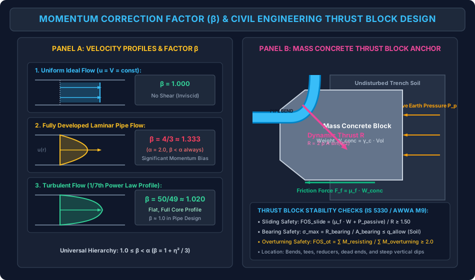
Applying the bulk mean velocity V=Q/A across finite conduit cross-sections introduces the Momentum Correction Factor (Boussinesq Coefficient)β=AV21∫Au2dA. For uniform flow, β=1.00; for laminar circular pipe flow, β=4/3≈1.33; and for turbulent pipe flow, β=50/49≈1.02. Because velocity fluctuations amplify momentum flux less aggressively than kinetic energy flux, the fundamental physical inequality 1.0≤β<α holds universally across all real flow fields.
In civil and hydraulic engineering, the primary application of the linear momentum equation is calculating the Dynamic Hydrodynamic Thrust (R) exerted by pressurized water streams on pipe bends, elbows, wyes, reducers, and dead ends:
The total force exerted by the fluid on a bend is composed of two interacting components:
Static Pressure Thrust: Resulting from the imbalance of internal hydrostatic/piezometric normal forces (p1A1 and p2A2).
Dynamic Momentum Thrust: Resulting from the forced change in direction and magnitude of the fluid momentum vector (ρQ(V1−V2)).
The Critical Directionality Trap: The static pressure force exerted by the downstream pipe on the control volume (p2A2) acts inward towards the interior of the control volume (opposing outward flow direction). Neglecting this sign inversion is the single most pervasive source of error in competitive examination calculations!
Civil Infrastructure Deliverable (Thrust Blocks): In buried water distribution networks and surface penstocks, flexible push-on joints cannot sustain axial tension. The unbonded resultant thrust R will pull bell-and-spigot joints apart, precipitating catastrophic pipeline rupture and urban flooding. Engineers must size massive Concrete Thrust Blocks designed to anchor the bend securely into undisturbed trench soil, verified against basal sliding (FOS≥1.50), soil bearing failure (σ≤qallow), and overturning (FOS≥2.0).
3. Reynolds Transport Theorem & Control Volume Linear Momentum Formulation
3.1 Reynolds Transport Theorem (RTT)
Let B represent an extensive fluid property (such as total mass m, linear momentum mV, or total energy E), and let βint=dB/dm be the corresponding intensive property (property per unit mass). The Reynolds Transport Theorem connects the time rate of change of property B for a moving material system to variations within a fixed spatial Control Volume (CV) bounded by Control Surface (CS):
dtdBsys=dtd∫CVρβintd∀+∫CSρβint(Vr⋅n^)dA
where Vr is the fluid velocity relative to the control surface, and n^ is the outward-pointing unit normal vector.
3.2 Application to Linear Momentum
For linear momentum, the extensive property is B=mV, so the intensive property is:
βint=dmd(mV)=V
Newton's second law for the fluid system states:
∑Fnet=(dtdPsys)
Substituting into the RTT for a fixed control volume (Vr=V):
∑Fnet=∂t∂∫CVρVd∀+∫CSρV(V⋅n^)dA
For steady flow (∂/∂t=0), the local temporal storage term vanishes:
∑Fnet=∫CSρV(V⋅n^)dA=∑m˙outVout−∑m˙inVin
3.3 Classification of Net Applied Forces (∑Fnet)
The net force acting on the fluid within the control volume consists of:
∑Fnet=Fbody+Fsurface
Body Forces (Fbody): Gravitational weight of the fluid enclosed within the control volume (W=∫CVρgd∀). In horizontal pipe bends, the vertical weight acts along the z-axis, exerting zero component in the horizontal x–y plane of motion.
Surface Forces (Fsurface):
Pressure Forces (Fp): Hydrostatic/piezometric normal forces acting across all open flow boundaries (inlet and outlet planes).
Shear and Normal Wall Reaction Forces (Fwall): The mechanical force exerted by the solid conduit walls on the fluid control volume (Fwall=Fxi^+Fyj^).
In practical 1D engineering analysis, pipe calculations utilize the cross-sectional bulk mean velocity V=Q/A. However, viscous friction at solid boundaries creates non-uniform velocity distributions u(y) or u(r).
The true rate of momentum flux transmitted across an elemental area dA is:
dM˙actual=(dm)u=(ρudA)u=ρu2dA
Integrating over the entire cross section A, the actual linear momentum flux is:
M˙actual=ρ∫Au2dA
If calculated naively using the 1D average velocity V:
M˙1D=(ρAV)V=ρAV2
Because the mean of squares is always greater than or equal to the square of the mean:
A1∫Au2dA≥V2
The Momentum Correction Factor (Boussinesq Coefficient)β is defined as:
β=M˙1DM˙actual=ρAV2ρ∫Au2dA=AV21∫Au2dA
4.1 Analytical Derivation for Fully Developed Laminar Pipe Flow
For laminar flow in a circular pipe of radius R, the Hagen-Poiseuille parabolic velocity distribution is:
u(r)=Umax[1−(Rr)2],V=2Umax
Let η=(r/R)2⟹2πrdr=πR2dη.
Substitute into the definition of β:
Universal Inequality (GATE CE):
For any real non-uniform velocity distribution:
1.0≤β<α
(If the velocity profile is expressed as u=V(1+η) where ∫ηdA=0, then to second-order approximation: β≈1+η2 and α≈1+3η2⟹α−1≈3(β−1)).
5. Dynamic Hydrodynamic Forces on Reducing Pipe Bends & Reducers
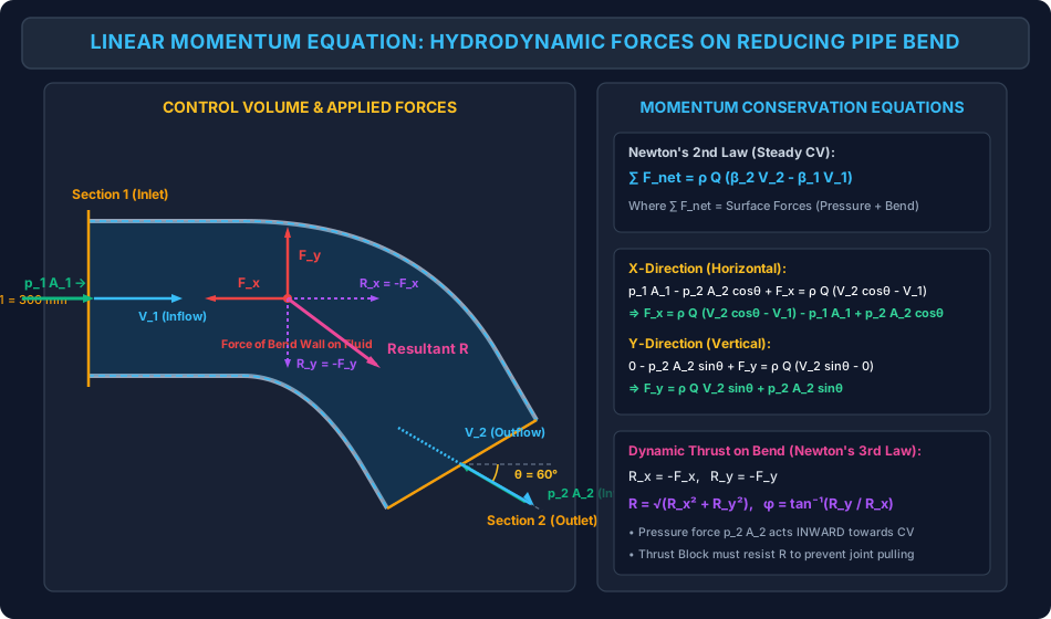
Consider a horizontal reducing pipe bend deflecting steady water flow through an angle θ in the x–y plane.
Section 1 (Inlet): Area A1, internal gauge pressure p1, velocity V1 directed along the +x axis.
Section 2 (Outlet): Area A2, internal gauge pressure p2, velocity V2 directed at angle θ to the +x axis.
                         ^ y
                         |           Section 2 (Outlet)
                         |             /
                         |            /  A2, p2, V2 at angle theta
                         |           +---
                         |          /
                         |         /  Bend Wall Reaction (Fx, Fy)
       p1*A1             |        /
      ======> [Section 1]+-------+-----------------------> x
         A1, p1, V1
5.1 X-Direction Momentum Conservation
Forces acting on the fluid control volume in the x-direction:
Pressure force at inlet: +p1A1 (acts in +x direction),
Pressure force at outlet: −p2A2cosθ (acts inward, opposing +x),
Component of force exerted by the solid bend wall on the fluid: +Fx.
Net external force in x:
∑Fx=p1A1−p2A2cosθ+Fx
Net momentum efflux rate in x:
ΔM˙x=m˙(β2V2x−β1V1x)=ρQ(β2V2cosθ−β1V1)
Equating:
p1A1−p2A2cosθ+Fx=ρQ(β2V2cosθ−β1V1)
Solving for the force exerted by the wall on the fluid:
Fx=ρQ(β2V2cosθ−β1V1)−p1A1+p2A2cosθ
5.2 Y-Direction Momentum Conservation
Forces acting on the fluid control volume in the y-direction:
Pressure force at inlet: 0 (flow is purely along x),
Pressure force at outlet: −p2A2sinθ (acts inward, opposing +y),
Component of force exerted by the solid bend wall on the fluid: +Fy.
Net external force in y:
∑Fy=0−p2A2sinθ+Fy
Net momentum efflux rate in y:
ΔM˙y=m˙(β2V2y−β1V1y)=ρQ(β2V2sinθ−0)
Equating:
−p2A2sinθ+Fy=ρQβ2V2sinθ
Solving for the wall reaction force:
Fy=ρQβ2V2sinθ+p2A2sinθ=(ρQβ2V2+p2A2)sinθ
5.3 Force Exerted by Fluid on the Pipe Bend (Newton's Third Law)
By Newton's third law of action and reaction, the force R exerted by the moving fluid stream on the pipe bend is equal in magnitude and opposite in direction to the force F exerted by the bend on the fluid:
Using the half-angle trigonometric identity 2(1−cosθ)=2sin(θ/2):
R=2(pA+ρQV)sin(2θ)
The resultant thrust acts along the external angle bisector:
ϕ=−(2180∘−θ)
Bend Deflection Angle (θ)
Resultant Thrust Formula R
Angle of Action (ϕ)
45∘ Bend
R=2(pA+ρQV)sin22.5∘≈0.765(pA+ρQV)
−67.5∘
90∘ Standard Elbow
R=2(pA+ρQV)≈1.414(pA+ρQV)
−45.0∘
180∘ U-Bend / Return Bend
R=2(pA+ρQV)
0∘ (Direct axial pull)
6. Static Pressure vs Dynamic Momentum Thrust: The Directionality Trap
In competitive examinations and field engineering calculations, catastrophic errors frequently occur due to conceptual misunderstanding of pressure force vectors:
1. Pressure Acts INWARD on the Control Volume
Pressure is a compressive normal stress. It always pushes into a surface.
At inlet Section 1, the upstream fluid pushes into the control volume: +p1A1i^.
At outlet Section 2, the downstream fluid pushes back into the control volume against the outward flow: Fp2=−p2A2n^2.
Common Mistake: Students mistakenly write +p2A2 because flow is leaving the control volume. Remember: Flow direction does not alter the fact that fluid pressure is compressive!
2. Relative Magnitude of Static vs Dynamic Thrust
In typical civil water distribution mains (p∼400–800 kPa,V∼1.5–3.0 m/s):
Static Pressure Force Fp=pA=(500×103)×4π(0.40)2≈62.8 kNDynamic Momentum Force Fm=ρQV=ρAV2=1000×4π(0.40)2×(2.78)2≈0.97 kNFmFp=0.9762.8≈65:1
In high-pressure civil conduits, Static Pressure Thrust dominates dynamic momentum thrust by a factor of 50 to 100! However, during transient water hammer surges or in high-velocity impulse turbines (V∼100 m/s), dynamic momentum thrust becomes dominant.
7. Civil Engineering Application: Mass Concrete Thrust Block Design
7.1 The Physical Vulnerability of Buried Pipeline Joints
Modern municipal water supply systems use Ductile Iron (DI), Prestressed Concrete Cylinder Pipes (PCCP), or HDPE pipes joined using flexible push-on rubber gasket joints (e.g., Tyton joints).
These joints provide watertight seals under internal hydrostatic pressure while accommodating ground settlement and thermal expansion.
However, flexible push-on joints possess zero tensile restraint capacity.
When pressurized water encounters a bend, tee, or reducer, the resultant hydrodynamic thrust R attempts to push the fitting off the pipe barrel. Without external anchorage, the joint pulls apart instantly.
7.2 Structural Function of a Thrust Block (IS 5330 / AWWA M9)
A Thrust Block is an in-situ cast mass concrete block (typically M15 or M20 grade plain concrete) placed between the pipe fitting and the undisturbed vertical trench wall:
It transfers the resultant thrust R across a wide contact surface area to the native soil.
It mobilizes the passive earth resistance of the undisturbed trench embankment.
Its self-weight generates basal friction along the trench floor.
       Plan View (Looking Down):
                         Pipe Line
                            ||
                            ||
                            ||   Resultant Thrust R
                        ====++=======>  [ Mass Concrete ] ===> Passive Soil
                       /    ||             [ Thrust Block ]       Resistance
                      /     ||                 Weight W
               Pipe  /
8.1 Hydrodynamic Forces on Pipe Bend Control Volume
The schematic below presents the complete vector control volume force resolution on an inclined reducing pipe bend, detailing inlet/outlet pressure vectors, fluid momentum fluxes, wall reaction forces, and the resultant thrust vector.
The multi-panel diagram below contrasts velocity profile shapes and their corresponding β factors against the geotechnical stability mechanics of a civil mass concrete thrust block anchor.
9. Step-by-Step Numerical Problems with Complete Calculations
Problem 1: Reducing 60° Pipe Bend with Energy Loss & Dynamic Force Resolution
Problem Statement:
A horizontal reducing pipe bend deflects a steady water stream (ρ=1000 kg/m3,γ=9810 N/m3) through a deflection angle θ=60∘.
Inlet diameter: D1=300 mm=0.30 m.
Outlet diameter: D2=150 mm=0.15 m.
Volumetric flow rate: Q=0.250 m3/s (250 L/s).
Pressure at inlet: p1=300 kPa=300×103 N/m2.
Head loss through the bend is given as hL=0.402gV22.
Assume uniform velocity profiles at inlet and outlet (β1=β2=1.0).
Take g=9.81 m/s2.
Determine:
Flow velocities V1 and V2 and their velocity heads,
Head loss hL and static pressure p2 at the outlet,
Force components Fx,Fy exerted by the bend wall on the water,
Resultant force R exerted by the water on the bend and its inclination ϕ to the +x axis.
Solution & Step-by-Step Calculation:
Step 1: Compute cross-sectional areas and flow velocities
A1=4πD12=4π(0.30)2=0.0706858 m2A2=4πD22=4π(0.15)2=0.0176715 m2V1=A1Q=0.07068580.250=3.53678 m/s≈3.537 m/sV2=A2Q=0.01767150.250=14.14711 m/s≈14.147 m/s
Velocity heads:
2gV12=2×9.81(3.53678)2=19.6212.5088=0.63755 m2gV22=2×9.81(14.14711)2=19.62200.1407=10.20085 m
Head loss in bend:
hL=0.40×2gV22=0.40×10.20085=4.08034 m
Step 2: Compute outlet pressure p2 using extended Bernoulli equation
Horizontal bend ⟹z1=z2.
p1A1=300,000×0.0706858=21,205.75 Np2A2cos60∘=166,155.9×0.0176715×0.50=2,936.22×0.50=1,468.11 NPressure term (p1A1−p2A2cos60∘)=21,205.75−1,468.11=19,737.64 NMomentum term ρQ(V2cos60∘−V1)=1000×0.250×(14.14711×0.50−3.53678)=250×(7.07355−3.53678)=250×3.53678=884.19 N
Solving for Fx:
19,737.64+Fx=884.19⟹Fx=884.19−19,737.64=−18,853.45 N
Step 4: Linear Momentum Equation in Y-Direction
∑Fy=0−p2A2sin60∘+Fy=ρQ(V2sin60∘−0)
Compute individual terms:
sin60∘=0.866025p2A2sin60∘=2,936.22×0.866025=2,542.84 NρQV2sin60∘=1000×0.250×14.14711×0.866025=250×12.25175=3,062.94 N
Solving for Fy:
−2,542.84+Fy=3,062.94⟹Fy=3,062.94+2,542.84=5,605.78 N
Step 5: Force Exerted by Water on the Bend (R)
By Newton's third law:
(The resultant thrust is 19.67 kN directed at 16.56∘ below the horizontal +x axis).
Problem 2: Mathematical Proof & Error Evaluation of Momentum Correction Factor (β)
Problem Statement:
Derive from first principles that β=4/3 for laminar flow in a circular conduit having velocity distribution u(r)=U0[1−(r/R)2].
Derive that β=50/49≈1.0204 for turbulent flow obeying the 1/7th power law u(r)=U0(1−r/R)1/7.
In a dredging slurry pipeline conveying dense sediment-water mixture (ρ=1350 kg/m3) under laminar conditions with volumetric discharge Q=0.080 m3/s through pipe diameter D=200 mm, compute the true dynamic momentum flux in N. Calculate the percentage error if an engineer naively neglects β by setting β=1.0.
Solution & Step-by-Step Calculation:
Step 1: Proof for Laminar Flow
Mean velocity V=U0/2.
(Neglecting β in laminar flow underpredicts dynamic momentum thrust by exactly 25%).
Problem 3: Design of Mass Concrete Thrust Block at a 90° Pipeline Bend
Problem Statement:
A ductile iron municipal water transmission pipeline of diameter D=400 mm=0.40 m carries water under steady flow at volumetric discharge Q=0.350 m3/s and internal working gauge pressure p=500 kPa=500×103 N/m2.
At a horizontal 90∘ elbow (θ=90∘), compute the static pressure force Fp, dynamic momentum force Fm, and the total resultant hydrodynamic thrust R exerted by the water on the bend.
To anchor the elbow, a mass concrete thrust block (γconc=24.0 kN/m3) is cast against undisturbed trench soil. The allowable passive soil bearing capacity is qallow=150 kPa, and the coefficient of friction between the concrete block base and the trench floor is μf=0.45.
Neglecting passive soil resistance on the sides and relying purely on base friction with a factor of safety FOSslide=1.50, determine the required mass of concrete and concrete volume in m3.
Determine the minimum contact bearing area Abearing required against the trench soil.
Solution & Step-by-Step Calculation:
Step 1: Compute Flow Velocity, Cross-Sectional Area, and Forces
A=4πD2=4π(0.40)2=0.125664 m2V=AQ=0.1256640.350=2.78521 m/s
Step 4: Required Soil Contact Bearing Area
The resultant thrust R=90.24 kN must be transferred safely to the native trench wall without exceeding the allowable soil bearing capacity qallow=150 kPa:
Abearing≥qallowR×FOSbearing
Using working allowable stress design where factor of safety is inherent in qallow:
Abearing=qallowR=150 kN/m290.236 kN=0.6016 m2
If applying an explicit engineering factor of safety FOS=1.50:
Abearing, safe=1501.50×90.236=0.9024 m2≈0.90 m2
(Design Specification: Cast a concrete block of dimensions 2.5 m (length)×2.5 m (width)×2.0 m (depth)=12.5 m3, providing a vertical bearing face of 2.5 m×2.0 m=5.0 m2≫0.90 m2, guaranteeing complete structural stability).
10. High-Yield Exam Pitfalls, Traps & Shortcuts
The Outlet Pressure Direction Trap (p2A2 Acts Inward):
Trap: Writing the x-force balance as ∑Fx=p1A1+p2A2cosθ+Fx.
Truth: Fluid pressure is always compressive. It pushes inward into the control volume; therefore, at the outlet, its component along +x is −p2A2cosθ.
The "Dynamic Force Equals Pressure Force" Fallacy:
Trap: Neglecting pA and using only ρQΔV for the force on a pipe bend.
Truth: In closed-conduit water mains, the static pressure force pA is often 50 to 100 times larger than the dynamic momentum force ρQV. Never omit pA unless the problem explicitly states that the pipe discharges freely into the atmosphere (p=0).
β vs α Hierarchy:
Always remember: 1.0≤β<α.
Laminar pipe flow: β=4/3≈1.33, α=2.0.
Turbulent pipe flow: β=50/49≈1.02, α≈1.06.
Uniform flow: β=1.0, α=1.0.
Symmetrical Bend Resultant Formula Shortcut:
For any constant-diameter bend of angle θ:
R=2(pA+ρQV)sin(2θ)
For θ=90∘: R=2(pA+ρQV).
For θ=60∘: R=(pA+ρQV) (since 2sin30∘=1).
For θ=180∘: R=2(pA+ρQV).
Force on Fluid vs Force on Pipe:
Fx,Fy: Force exerted by the bend wall on the fluid.
Rx=−Fx,Ry=−Fy: Force exerted by the fluid on the bend (Thrust on anchors). Always check which force the question is asking for!
11. Multi-Exam Question Bank (GATE, ESE, SSC JE, State AE, RRB JE)
Question 1 (GATE CE — Multiple Choice Question)
Water flows through a 90∘ horizontal pipe bend of uniform diameter D=200 mm carrying a discharge of 0.100 m3/s. The pressure at both the inlet and outlet is 200 kPa. Neglecting friction and taking ρ=1000 kg/m3, the magnitude of the resultant force exerted by the water on the bend is:
A)6.28 kN
B)8.92 kN
C)9.36 kN
D)12.56 kN
Detailed Solution:
Area A=4π(0.2)2=0.031416 m2.
Velocity V=0.0314160.100=3.183 m/s.
Static pressure force Fp=pA=200×103×0.031416=6,283.2 N=6.283 kN.
Dynamic momentum force Fm=ρQV=1000×0.100×3.183=318.3 N=0.318 kN.
Total component per axis: Fp+Fm=6.283+0.318=6.601 kN.
For a 90∘ bend:
R=2(Fp+Fm)=1.4142×6.6015 kN=9.336 kN≈9.34 kN to 9.36 kN
Matching option C.
Correct Answer: C
Question 2 (UPSC ESE Paper-II)
What is the value of the momentum correction factor (β) for fully developed laminar flow through a circular pipe?
A)1.00
B)1.20
C)1.33
D)2.00
Detailed Solution:
For parabolic Hagen-Poiseuille velocity profile u(r)=Umax[1−(r/R)2], integration yields β=AV21∫u2dA=34≈1.33.
(Note: α=2.0 is the kinetic energy correction factor; do not confuse α and β).
Correct Answer: C
Question 3 (SSC JE)
A thrust block in a municipal water transmission pipeline is provided at:
A) The summit of a siphon
B) Horizontal and vertical pipe bends, tees, and reducers
C) The entrance of a venturimeter
D) Along straight uniform pipe reaches
Detailed Solution:
Thrust blocks are mass concrete structures constructed at bends, tees, reducers, and dead ends to resist the dynamic and static hydrodynamic thrust that would otherwise pull flexible pipe joints apart.
Correct Answer: B
Question 4 (State PSC AE)
Water enters a horizontal reducing bend with velocity V1 and exits at angle θ with velocity V2. If A1,p1 and A2,p2 are areas and pressures at inlet and exit respectively, the force Fx exerted by the bend on the fluid in the x-direction (inlet along +x) is:
A)ρQ(V2cosθ−V1)−p1A1+p2A2cosθ
B)ρQ(V2cosθ−V1)+p1A1−p2A2cosθ
C)ρQ(V1−V2cosθ)+p1A1−p2A2cosθ
D)ρQ(V2cosθ−V1)−p1A1−p2A2cosθ
Detailed Solution:
Linear momentum equation: ∑Fx=p1A1−p2A2cosθ+Fx=ρQ(V2cosθ−V1).
Rearranging: Fx=ρQ(V2cosθ−V1)−p1A1+p2A2cosθ.
Correct Answer: A
Question 5 (RRB JE)
For any fluid flow with a non-uniform velocity distribution across the cross section, the kinetic energy correction factor α and the momentum correction factor β are related as:
A)α<β<1.0
B)1.0≤β<α
C)α=β>1.0
D)β>α>1.0
Detailed Solution:
Because cubic velocity terms grow faster than quadratic terms, the Coriolis coefficient α is always strictly greater than the Boussinesq coefficient β for non-uniform flow, and both are ≥1.0. Hence, 1.0≤β<α.
Correct Answer: B
12. Comprehensive Summary, Formula Cheatsheet & Academic References
Master Formula Cheatsheet
Control Volume Linear Momentum:Momentum Correction Factor:Universal Hierarchy:X-Force Balance on Fluid:Y-Force Balance on Fluid:Force on Bend (Thrust):Constant-Diameter Bend Thrust:Thrust Block Sliding Safety:Thrust Block Soil Bearing Area:∑Fnet=M˙out−M˙in=ρQ(β2V2−β1V1)β=AV21∫Au2dA(Laminar: 4/3≈1.33;Turbulent: 50/49≈1.02)1.0≤β<α(α−1≈3(β−1))Fx=ρQ(β2V2cosθ−β1V1)−p1A1+p2A2cosθFy=(ρQβ2V2+p2A2)sinθRx=−Fx,Ry=−Fy,R=Rx2+Ry2R=2(pA+ρQV)sin(2θ)(For 90∘:2(pA+ρQV))FOSslide=RμfWblock+Ppassive≥1.50Abearing≥qallow, soilR
Academic References & Standard Source Texts
White, F. M. (2016). Fluid Mechanics (8th ed.). McGraw-Hill Education. Chapter 3: Integral Relations for a Control Volume (Sections 3.3 & 3.4: Linear Momentum Equation).
Modi, P. N., & Seth, S. M. (2018). Hydraulics and Fluid Mechanics Including Hydraulics Machines (22nd ed.). Standard Book House, New Delhi. Chapter 8: Momentum Equation and its Applications.
Streeter, V. L., Wylie, E. B., & Bedford, K. W. (1998). Fluid Mechanics (9th ed.). WCB/McGraw-Hill. Chapter 3: Linear Momentum.
IS 5330: Criteria for Design of Anchor Blocks for Penstocks with Expansion Joints. Bureau of Indian Standards, New Delhi.
AWWA M9: Concrete Thrust Blocking for Ductile-Iron Pipe. American Water Works Association.
CPHEEO: Manual on Water Supply and Treatment (3rd ed.). Ministry of Housing and Urban Affairs, Government of India.