Hydraulic Transients, Water Hammer, Elastic Conduits & Surge Tanks
In this chapter (4 topics)
On this page
- 1. Module Overview & Pedagogical Scope
- 2. Official Examination Syllabus Mapping
- 3. Fundamental Physical Principles & Governing Assumptions
- 4. Mathematical Derivations & Rigorous Proofs
- Sub-derivation A: Physical Mechanism of Acoustic Wave Propagation (The 4-Phase Cycle)
- Sub-derivation B: Derivation of Acoustic Wave Speed (C) in Elastic Conduits
- Sub-derivation C: Rapid Valve Closure (Joukowsky Equation)
- Sub-derivation D: Slow Gradual Closure (Allievi Formulation)
- Sub-derivation E: Surge Tank Hydraulic Mechanics & Water Upsurge
- Sub-derivation F: Surge Tank Stability Criteria (Thoma's Formula)
- 5. Technical Diagrams & Interactive Architectural Schematics
- Figure 1: Water Hammer Wave Reflections & Closure Waveforms
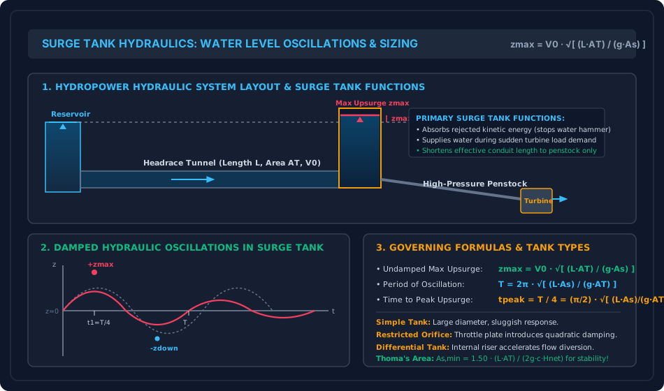
- Figure 2: Surge Tank Hydraulic Layout & Water Level Oscillations
- 6. Comparative Engineering Analysis & Parameter Regimes
- 7. Worked Numerical Examples (Pre-Calculated & Verified)
- Problem 1: Acoustic Celerity in Rigid vs Elastic Steel Penstocks
- Problem 2: Rapid vs Slow Valve Closure (Joukowsky vs Allievi)
- Problem 3: Surge Tank Sizing & Water Level Upsurge
- 8. High-Yield Examination Traps & Ambiguities
- 9. Real-World Engineering Applications & Case Studies
- 10. Cross-Disciplinary & Downstream Dependencies
- 11. Summary Formula Cheat Sheet & Memory Anchors
- 12. Comprehensive References & Standard Codes
1. Module Overview & Pedagogical Scope
Hydraulic transients encompass the unsteady, dynamic behavior of liquid flows inside closed pressurized conduits triggered by rapid modifications to boundary conditions—such as sudden closure or opening of control valves, tripping or startup of booster pumps, and instantaneous electrical load rejection on hydroelectric turbine runners.
When steady fluid motion is abruptly halted, the kinetic energy of the flowing fluid column () cannot instantly vanish; it is transformed into acoustic strain energy stored in the compressibility of the fluid and the elastic hoop expansion of the conduit walls. This creates intense acoustic pressure waves that propagate back and forth along the conduit at acoustic celerities (), producing the violent hydraulic shock phenomenon known as Water Hammer.
This module provides a rigorous mathematical and physical analysis of:
- The fundamental 4-phase acoustic reflection cycle of pressure wave propagation over the round-trip period () and full reflection cycle ().
- Derivation of acoustic wave speed () in rigid versus elastic thin-walled and thick-walled pipes under varying longitudinal anchoring constraints ().
- Rapid closure dynamics governed by the Joukowsky Equation ().
- Slow gradual closure dynamics governed by Allievi's Equations ().
- Surge tank hydraulic mechanics: kinetic-to-potential energy conversion, maximum water upsurge (), oscillation periods, tunnel friction damping, and Thoma's hydrodynamic stability criterion.
2. Official Examination Syllabus Mapping
Website note: this mapping is from the author’s notes. It has not been checked against the official notification for each examination; confirm the current syllabus with the examining body.
| Examination Body | Syllabus Clause / Core Topic Reference | Focus Regimes & Weightage |
|---|---|---|
| GATE CE (IITs / IISc) | Fluid Mechanics: Hydraulic transients; water hammer in pipes; acoustic wave velocity in elastic pipes; rapid and gradual closure; surge tanks. | Critical High-Yield Topic (1 to 2 questions annually; celerity calculations, rapid vs slow closure thresholds, maximum surge ). |
| UPSC ESE (Prelims & Mains) | Paper-II Fluid Mechanics: Water hammer pressure and acoustic wave velocity, rapid and slow closure, Allievi and Joukowsky equations, surge tanks: types, functions and oscillations. | Core Subjective & Objective Focus (15–20 marks in Mains; 2–4 MCQs in Prelims). |
| SSC JE & State AE / JE | Water hammer in pipes, sudden and gradual closure, celerity of pressure wave, purpose and types of surge tanks. | High Frequency (Direct formula substitutions: , , ). |
| RRB JE (CBT-2) | Water hammer, cavitation, surge tanks in hydropower systems. | Standard definitions, wave speed trends, and surge tank roles. |
3. Fundamental Physical Principles & Governing Assumptions
- Compressibility of Fluid: Unlike steady incompressible hydraulics, transient pressure wave analysis explicitly accounts for fluid volume elasticity, parameterized by the bulk modulus of elasticity of the liquid ( for water).
- Elasticity of Conduit Walls: The pipe walls expand and contract elastically in response to pressure transients, characterized by Young's modulus of elasticity () and Poisson's ratio ().
- One-Dimensional Acoustic Wave Propagation: Transverse pressure and velocity gradients are neglected; acoustic pressure wavefronts are planar and propagate longitudinally at characteristic speed .
- Critical Round-Trip Closure Time ():
- Rapid (Sudden) Closure: Valve closure time . The valve reaches full shutoff before the relief reflection wave from the reservoir can return to relieve the pressure at the valve face. The full Joukowsky surge develops.
- Slow (Gradual) Closure: Valve closure time . The returning relief wave reaches the valve while closure is still underway, mitigating the pressure surge.
4. Mathematical Derivations & Rigorous Proofs
Sub-derivation A: Physical Mechanism of Acoustic Wave Propagation (The 4-Phase Cycle)
Consider a long horizontal pipe of length connecting an open reservoir to a control valve at the downstream end, conveying water at steady velocity . At , the valve is closed instantaneously.
Phase 1 (): Compression Wave Moves Upstream
- Fluid immediately at the valve face is brought to complete rest ().
- The sudden deceleration creates a localized high-pressure zone ().
- The fluid compresses and the pipe expands elastically.
- This high-pressure wavefront propagates upstream toward the reservoir at acoustic celerity .
- At , the wave arrives at the reservoir inlet. The entire pipe is now expanded and at elevated pressure (), with fluid at rest ().
Phase 2 (): Relief Wave Reflects Downstream
- The pipe inlet is exposed to the constant reservoir pressure .
- Because of the pressure imbalance between the pipe interior () and the reservoir (), fluid starts discharging backward out of the pipe into the reservoir at velocity .
- A relief wave (pressure returning to , fluid moving backward at ) propagates downstream toward the closed valve at speed .
- At , the relief wave reaches the closed valve. The entire pipe is restored to normal pressure , but fluid is everywhere moving backward toward the reservoir at velocity .
Phase 3 (): Rarefaction Wave Propagates Upstream
- Because the valve is closed, fluid cannot continue flowing backward away from the closed valve face without creating a void.
- A sudden tension/drop in pressure occurs at the valve face: .
- The pipe contracts elastically below its normal diameter.
- This low-pressure rarefaction wave moves upstream toward the reservoir at speed .
- At , the wave reaches the reservoir. The entire pipe is now contracted at reduced pressure () with .
Cavitation Danger: If drops below the fluid's vapor pressure ( absolute), water column separation occurs, followed by catastrophic collapse when pressures reverse!
Phase 4 (): Inflow Restores Equilibrium
- The reservoir pressure exceeds the low pipe pressure (), driving water back into the pipe at .
- A wavefront restoring normal pressure travels downstream toward the valve.
- At , conditions return exactly to the initial state, completing one full acoustic oscillation cycle of period:
Sub-derivation B: Derivation of Acoustic Wave Speed () in Elastic Conduits
Consider an acoustic compression wave propagating upstream through fluid at celerity . In time , the wavefront travels distance .
- The fluid entering the wave is decelerated from to (velocity change ).
- Volume of fluid overtaken in time : .
1. Conservation of Mass:
The reduction in volume is accommodated by two physical mechanisms:
- Volumetric compression of the liquid:
- Radial elastic expansion of the pipe cross-section:
Total volume accommodated:
By mass continuity, the volume of incoming fluid halted during time is:
Equating the two expressions and canceling :
2. Momentum Equation across Wavefront:
Applying the momentum theorem to the fluid element of mass decelerating by :
3. Elastic Pipe Wall Deformation:
For a thin-walled conduit of diameter and wall thickness (), the hoop tensile stress induced by pressure surge is:
The circumferential hoop strain is , where is the conduit anchoring coefficient. Since cross-sectional area is :
4. Combining Equations to Solve for :
Substitute and into the mass conservation equation:
Dividing through by :
Inverting and taking the square root yields the Universal Acoustic Celerity Formula:
where is the acoustic speed in pure water confined within an infinitely rigid conduit.
Values of Pipe Support Factor ():
- Case 1 (Expansion joints throughout): Pipe is free to move longitudinally without axial stress:
- Case 2 (Anchored against longitudinal movement throughout): Pipe is restrained along its length:
- Case 3 (Anchored at upstream end only): Pipe expands axially under Poisson effect:
Sub-derivation C: Rapid Valve Closure (Joukowsky Equation)
When closure time , the full momentum of the fluid is arrested before any relief wave can arrive from the reservoir. From the momentum balance:
Expressing the surge in terms of equivalent hydraulic head rise ():
The maximum instantaneous total head acting at the valve face is:
where is the steady static reservoir head.
Sub-derivation D: Slow Gradual Closure (Allievi Formulation)
When closure occurs slowly over time , the valve closure process can be conceptualized as a sequence of incremental closures. The relief wave arrives at the valve face during closure, partially canceling the acoustic surge.
Assuming uniform, linear deceleration of the fluid column from to over duration :
Applying Newton's second law to the entire mass of water in the pipeline ():
However, during time , relief waves have traveled back and forth. Detailed characteristic analysis by Lorenzo Allievi (1902) shows that accounting for wave reflections over duration :
Boundary Verification:
When , Allievi's equation gives:which matches the Joukowsky rapid closure formula exactly at the boundary!
Sub-derivation E: Surge Tank Hydraulic Mechanics & Water Upsurge
A surge tank is an open vertical standpipe or reservoir shaft constructed at the junction between the low-pressure headrace tunnel and the high-pressure penstock.
1. Maximum Undamped Water Upsurge ():
Consider instantaneous complete shutdown of the turbine. The entire kinetic energy of the water column in the headrace tunnel (length , cross-sectional area , mass ) must be converted into gravitational potential energy of the water column rising inside the surge tank (cross-sectional area ).
- Kinetic energy of water in headrace tunnel:
- Work done against gravity by water rising to height in surge tank:
Equating :
2. Period of Water Level Oscillation ():
The equation of motion for the oscillating water mass neglecting friction is a simple harmonic oscillator:
The natural circular frequency is:
The period of oscillation is:
The time required to reach the peak maximum upsurge () from the instant of closure is one-quarter period:
3. Tunnel Friction Damping Correction (Frank / Jaeger Formula):
In reality, fluid friction in the headrace tunnel continuously dissipates kinetic energy during upsurge. If the initial steady-state friction head loss is , the actual damped upsurge is given by:
Friction damping typically reduces the peak surge by .
Sub-derivation F: Surge Tank Stability Criteria (Thoma's Formula)
When a turbine operates under a modern electronic governor demanding constant electrical power output (), small load perturbations can induce self-excited resonant water level oscillations.
To ensure that surge oscillations decay asymptotically rather than grow unstably, Dieter Thoma (1910) established the minimum required cross-sectional area of the surge tank:
where is the hydraulic resistance coefficient () and is the net operating head on the turbine.
In professional civil engineering practice (per IS 7396: Part 1), a safety factor of is mandated:
5. Technical Diagrams & Interactive Architectural Schematics
Figure 1: Water Hammer Wave Reflections & Closure Waveforms
The diagram below details the 4-phase acoustic reflection cycle, the critical round-trip closure time , and the fundamental difference between rapid (Joukowsky) and slow (Allievi) pressure waveforms.
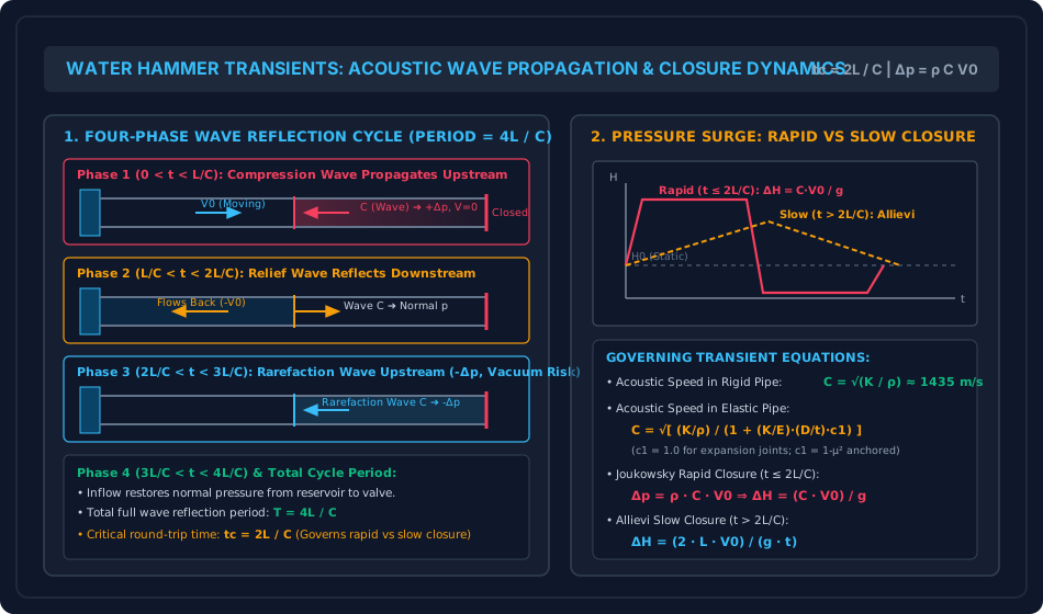
Figure 2: Surge Tank Hydraulic Layout & Water Level Oscillations
The diagram below illustrates the arrangement of the headrace tunnel, surge tank, and penstock, alongside the damped water level oscillation trajectory () and types of surge tanks.
6. Comparative Engineering Analysis & Parameter Regimes
| Characteristic Parameter | Rapid Closure () | Slow Closure () | Physical Explanation & Exam Focus |
|---|---|---|---|
| Valve Closure Duration () | Determined by comparison with acoustic round-trip time. | ||
| Relief Wave Status | Returns after valve is fully shut | Returns during valve closure | In slow closure, relief waves actively cancel the incoming pressure wave. |
| Pressure Surge Equation | (Joukowsky) | (Allievi) | Rapid is independent of and ; slow depends directly on . |
| Head Surge Equation | Rapid head surge is typically ; slow is much smaller. | ||
| Pressure Wavefront Shape | Steep rectangular step wave | Truncated triangular/sloping ramp | Rapid causes sharp impact shock ("hammering sound"). |
| Primary Protection Device | Rupture discs, fast relief valves | Slow motorized valve actuators | Controlled stroking times prevent rapid closure entirely. |
7. Worked Numerical Examples (Pre-Calculated & Verified)
Problem 1: Acoustic Celerity in Rigid vs Elastic Steel Penstocks
Statement:
A high-head hydroelectric steel penstock has internal diameter () and wall thickness (). The conduit conveys fresh water with density and bulk modulus of elasticity (). The Young's modulus of elasticity of the penstock steel is () and its Poisson's ratio is .
- Compute the acoustic wave velocity assuming the conduit is infinitely rigid.
- Determine the acoustic wave velocity in the elastic steel pipe fitted with slip-type expansion joints throughout ().
- Determine the acoustic wave velocity if the penstock is anchored against longitudinal movement throughout its length ().
- Compute the percentage reduction in acoustic wave speed caused by pipe wall elasticity.
Solution:
Step 1: Acoustic Wave Velocity in Rigid Conduit
Step 2: Geometric & Elastic Modulus Ratios
Step 3: Case (a) — Pipe with Expansion Joints ()
Step 4: Case (b) — Pipe Anchored Against Longitudinal Movement ()
Problem 2: Rapid vs Slow Valve Closure (Joukowsky vs Allievi)
Statement:
A steel penstock of total length , diameter , and thickness conveys water from an elevated reservoir under a static operating head . The steady initial flow velocity is . The acoustic celerity is determined as .
- Compute the critical closure time .
- Case A (Rapid Closure): If the turbine valve closes completely in , calculate the maximum water hammer pressure surge , head rise , and maximum total head .
- Case B (Slow Closure): If the valve closure time is extended to , calculate the resulting head surge , pressure surge , and maximum total head .
Solution:
Step 1: Critical Round-Trip Closure Time
Step 2: Case A — Closure in Since , this is strictly rapid (sudden) closure. The full Joukowsky surge develops:
Maximum total head at valve:
(The head increases by a factor of , which would rupture an unprotected conduit).
Step 3: Case B — Closure in Since , this is slow (gradual) closure. Applying Allievi's equation:
Maximum total head at valve:
(Extending closure time from to reduces the pressure surge by , from down to ).
Problem 3: Surge Tank Sizing & Water Level Upsurge
Statement:
A low-pressure headrace tunnel of diameter , length , and Darcy friction factor connects a reservoir to a simple cylindrical surge tank of internal diameter . The initial steady power generation discharge is ().
When turbine gates close completely and instantaneously due to sudden grid failure:
- Calculate the cross-sectional area of the headrace tunnel and the surge tank .
- Determine the initial steady friction head loss in the headrace tunnel.
- Compute the maximum water level upsurge above the static reservoir level neglecting friction damping.
- Compute the maximum upsurge accounting for headrace tunnel friction damping using Frank's formula.
- Determine the natural period of water oscillation and the time required to reach the peak water level.
Solution:
Step 1: Conduit and Surge Tank Areas
Step 2: Steady Headrace Tunnel Friction Loss
Step 3: Undamped Maximum Water Upsurge ()
Step 4: Damped Maximum Upsurge (Accounting for Friction) Using Frank's formula:
(Friction damping reduces the required surge tank height by , saving substantial civil excavation costs).
Step 5: Oscillation Period and Time to Peak Upsurge
Time to peak upsurge:
8. High-Yield Examination Traps & Ambiguities
| S.No. | Examination Trap / Pitfall | Correct Engineering Distinction | Target Examination |
|---|---|---|---|
| 1 | Rapid vs Slow Closure Classification: Checking against instead of . | The critical closure time is strictly the round-trip time , NOT the one-way transit time . Rapid closure requires . | GATE CE, UPSC ESE |
| 2 | Joukowsky Head Surge Formula: Forgetting gravity in . | Pressure surge is (in ). Head surge is (in ). Dividing by is essential. | SSC JE, State AE |
| 3 | Pipe Support Factor in Acoustic Speed: Assuming is independent of anchoring. | Conduit anchoring alters acoustic wave speed by up to : (slip joints), (anchored throughout), (anchored at upstream end only). | GATE CE, ESE Mains |
| 4 | Negative Pressure / Cavitation during Wave Cycle: Overlooking Phase 3 vacuum risk. | In Phase 3 (), a negative pressure wave () sweeps the conduit. If absolute pressure drops below water vapor pressure ( abs), pipe wall buckling and cavitation column separation occur. | UPSC ESE, GATE CE |
| 5 | Surge Tank Area Ratio: Inverting and in vs . | ( is in the numerator), whereas ( is in the numerator!). Memorize: Larger tank area reduces upsurge () but increases oscillation period (). | GATE CE, SSC JE |
9. Real-World Engineering Applications & Case Studies
- Hydroelectric Power Plant Load Rejection:
When a Francis turbine drops electrical load due to a grid transmission fault, the governor slams the wicket gates shut within . As proven in Problem 2, without a surge tank, the pressure surge would burst the penstock. The surge tank intercepts the flow, converting kinetic energy into a gentle water rise. - Municipal Pumping Main Power Failure (Column Separation):
When electrical power trips at a municipal raw water pumping station, pumps spin down in . Downstream check valves slam shut, triggering negative pressure waves that can flatten thin-walled steel pipes under atmospheric pressure. Air-cushion vessels and vacuum breaker valves are installed to inject air and prevent conduit collapse. - Penstock Burst Disasters (Sayano-Shushenskaya & Oigawa):
Historical hydropower accidents have underscored the catastrophic power of water hammer. Inadequate governor closure timing or defective air release valves have sheared thick alloy steel penstocks and flooded underground machine halls.
10. Cross-Disciplinary & Downstream Dependencies
[Fluid Mechanics: Ch 06 Topic 04 Hydraulic Transients]
        │
        ├──► [Subject 04: Water Resources & Hydrology]
        │         ├─► Hydroelectric Powerhouse Design (Turbine Governors & Penstocks)
        │         └─► Surge Tank Structural Stability & Rock Cavern Excavation
        │
        ├──► [Subject 09: Environmental Engineering]
        │         └─► Pump Trip Protection in Water Mains (Air Vessels & Surge Anticipator Valves)
        │
        └──► [Fluid Mechanics: Ch 08 Hydraulic Machinery]
                  └─► Turbine Regulation, Runaway Speed & Water Hammer Interplay
11. Summary Formula Cheat Sheet & Memory Anchors
- Acoustic Wave Speed:
- Critical Round-Trip Closure Time:
- Joukowsky Rapid Closure ():
- Allievi Slow Closure ():
- Surge Tank Dynamics:
- Undamped Max Upsurge:
- Natural Period:
- Time to Peak:
- Damped Upsurge:
- Thoma Stability Area:
12. Comprehensive References & Standard Codes
- Wylie, E. B., & Streeter, V. L. (1993). Fluid Transients in Systems, Prentice Hall, Englewood Cliffs, NJ.
- Parmakian, J. (1963). Waterhammer Analysis, Dover Publications, New York.
- IS 7396 (Part 1): 1985 (Criteria for Hydraulic Design of Surge Tanks: Simple, Restricted Orifice and Differential Surge Tanks).
- IS 5330: 1984 (Criteria for Design of Anchor Blocks for Penstocks Along Slopes).
- Chaudhry, M. H. (2014). Applied Hydraulic Transients, 3rd Edition, Springer.