SA-07-03 Chapter 07 · Plastic Analysis of Structures

Plastic Analysis of Continuous Beams & Fixed/Propped Cantilevers

Subject
Structural Analysis
Chapter
07 — Plastic Analysis of Structures
Prerequisites
Plastic Hinges & Shape Factor (SA-07-01), Plastic Collapse Theorems & Mechanisms (SA-07-02), Three-Moment Equation (SA-03-02).
Target Examinations
GATE CE, UPSC ESE, SSC JE, State AE, RRB JE, State JE
Master Directory
civil_/notes/structural_analysis/07_plastic_analysis/03_plastic_analysis_beams.md
In this chapter (4 topics)
On this page

1. Introduction & Conceptual Foundations

In indeterminate flexural members, the formation of the first plastic hinge at the section of maximum bending moment does not precipitate structural collapse. Instead, it eliminates one degree of static indeterminacy (Ds→Ds−1D_s \to D_s - 1). The structure continues to sustain increased load through plastic moment redistribution, during which the resisting moment at the yielded hinge remains locked at its plastic capacity (MpM_p) while adjacent, less-stressed cross-sections absorb the additional load increments.

Collapse occurs only when a sufficient number of plastic hinges form to transform the structure (or an isolated portion of it) into an unstable kinematic mechanism.

   Determinate Beam (D_s = 0)  ===> 1 Plastic Hinge required for collapse (N_h = 1)
   Propped Cantilever (D_s = 1) ===> 2 Plastic Hinges required for collapse (N_h = 2)
   Fixed-Ended Beam (D_s = 2)   ===> 3 Plastic Hinges required for collapse (N_h = 3)
   Continuous Beam (N spans)    ===> Local Span Mechanism governs (Partial Collapse)
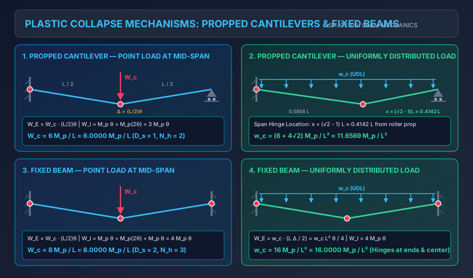
Plastic Collapse Mechanisms for Propped Cantilevers and Fixed Beams

2. Complete vs. Partial Collapse in Flexural Systems

  1. Complete Collapse: A collapse mode where the entire structure becomes a kinematic mechanism simultaneously. This requires: Nh=Ds+1N_h = D_s + 1 (e.g., fixed-ended beam where all 3 hinges form simultaneously).
  2. Partial Collapse: A collapse mode where one isolated span or sub-component forms a localized mechanism while the rest of the structure remains geometrically stable and indeterminate. In continuous beams spanning multiple supports, partial collapse almost invariably governs: Nh,span=Ds,span+1N_{h,\text{span}} = D_{s,\text{span}} + 1 (e.g., in a 5-span continuous bridge, the weakest span collapses with 2 or 3 hinges while the other 4 spans remain intact).
  3. Over-Complete Collapse: A collapse mode involving two or more independent mechanisms simultaneously, with Nh>Ds+1N_h > D_s + 1.

3. Mathematical Formulations for Propped Cantilever Beams

A propped cantilever of span LL is fixed at one end (say, left end A) and supported by a simple roller prop at the other end (right end B). The degree of static indeterminacy is:

Ds=1D_s = 1

Collapse requires Nh=Ds+1=1+1=2N_h = D_s + 1 = 1 + 1 = \mathbf{2} plastic hinges.

  • Hinge 1 (Hogging): Must form at the built-in fixed support A, where MA=MpM_A = M_p.
  • Hinge 2 (Sagging): Forms within the span at the section of maximum positive bending moment.
  • (Note: The simple roller prop B cannot develop a bending moment, so no hinge forms at B).

3.1 Propped Cantilever under Concentrated Load WW at Mid-Span

  • Hinges form at fixed end A and at mid-span under the load:
    • Let downward deflection under the load be Δ=L2θ\Delta = \frac{L}{2} \theta.
    • Rotation at fixed end A: θA=θ\theta_A = \theta.
    • Rotation at mid-span hinge: θC=θA+θB=θ+θ=2θ\theta_C = \theta_A + \theta_B = \theta + \theta = 2\theta.
  • Virtual Work Equation (WE=WIW_E = W_I): WE=Wc⋅Δ=Wc⋅(L2θ)W_E = W_c \cdot \Delta = W_c \cdot \left(\frac{L}{2} \theta\right) WI=MpθA+MpθC=Mp(θ)+Mp(2θ)=3MpθW_I = M_p \theta_A + M_p \theta_C = M_p (\theta) + M_p (2\theta) = 3 M_p \theta Equating WE=WIW_E = W_I: Wc(L2θ)=3Mpθ  ⟹  Wc=6MpL=6.0000MpLW_c \left(\frac{L}{2} \theta\right) = 3 M_p \theta \implies \mathbf{W_c = \frac{6 M_p}{L} = 6.0000 \frac{M_p}{L}}

3.2 Propped Cantilever under Concentrated Load WW at Distance aa from Fixed End

For a point load at distance aa from fixed end A and bb from roller prop B (a+b=La + b = L):

Δ=aθ1=bθ2  ⟹  θ2=abθ1\Delta = a \theta_1 = b \theta_2 \implies \theta_2 = \frac{a}{b} \theta_1 θA=θ1,θC=θ1+θ2=θ1(1+ab)=θ1Lb\theta_A = \theta_1, \quad \theta_C = \theta_1 + \theta_2 = \theta_1 \left(1 + \frac{a}{b}\right) = \theta_1 \frac{L}{b} WE=WcΔ=Wc(aθ1)W_E = W_c \Delta = W_c (a \theta_1) WI=MpθA+MpθC=Mpθ1+Mpθ1Lb=Mpθ1(1+Lb)=Mpθ1L+bbW_I = M_p \theta_A + M_p \theta_C = M_p \theta_1 + M_p \theta_1 \frac{L}{b} = M_p \theta_1 \left(1 + \frac{L}{b}\right) = M_p \theta_1 \frac{L + b}{b} Wc(aθ1)=Mpθ1L+bb  ⟹  Wc=Mp(L+b)abW_c (a \theta_1) = M_p \theta_1 \frac{L + b}{b} \implies \mathbf{W_c = \frac{M_p (L + b)}{a b}}

3.3 Propped Cantilever under Uniformly Distributed Load (UDL) ww

Under a distributed load, the exact location of the sagging plastic hinge within the span is not known a priori and must be derived mathematically.

       Fixed A (x=0)                  Sagging Hinge C            Prop B (x=L)
         [===================================O======================^]
         |<------------- L - x ------------->|<------- x ---------->|

Let the span hinge C form at a distance xx from the roller prop B (so distance from fixed end A is L−xL - x):

  1. Kinematic Work Formulation:

    • Let deflection at hinge C be Δ\Delta.
    • Rotation of segment AC: θA=ΔL−x\theta_A = \frac{\Delta}{L - x}.
    • Rotation of segment CB: θB=Δx\theta_B = \frac{\Delta}{x}.
    • Total rotation at hinge C: θC=θA+θB=Δ(1L−x+1x)=ΔLx(L−x)\theta_C = \theta_A + \theta_B = \Delta \left(\frac{1}{L - x} + \frac{1}{x}\right) = \Delta \frac{L}{x(L - x)}.
    • Internal Plastic Work: WI=MpθA+MpθC=MpΔL−x+MpΔLx(L−x)=MpΔ[x+Lx(L−x)]W_I = M_p \theta_A + M_p \theta_C = M_p \frac{\Delta}{L - x} + M_p \Delta \frac{L}{x(L - x)} = M_p \Delta \left[ \frac{x + L}{x(L - x)} \right]
    • External Work done by UDL: WE=w×(Deflected Area)=w×(12LΔ)=wLΔ2W_E = w \times (\text{Deflected Area}) = w \times \left( \frac{1}{2} L \Delta \right) = \frac{w L \Delta}{2}
    • Equating WE=WIW_E = W_I: wLΔ2=MpΔ[L+xx(L−x)]  ⟹  w(x)=2Mp(L+x)Lx(L−x)\frac{w L \Delta}{2} = M_p \Delta \left[ \frac{L + x}{x(L - x)} \right] \implies w(x) = \frac{2 M_p (L + x)}{L x (L - x)}
  2. Optimization (Upper Bound Minimization): To find the true critical mechanism, we minimize w(x)w(x) with respect to xx:

    dwdx=0  ⟹  ddx[L+xxL−x2]=0\frac{d w}{d x} = 0 \implies \frac{d}{dx} \left[ \frac{L + x}{x L - x^2} \right] = 0 (1)(xL−x2)−(L+x)(L−2x)=0(1)(x L - x^2) - (L + x)(L - 2x) = 0 xL−x2−(L2−2xL+xL−2x2)=0x L - x^2 - \left( L^2 - 2x L + x L - 2x^2 \right) = 0 x2+2Lx−L2=0x^2 + 2 L x - L^2 = 0

    Solving the quadratic equation:

    x=−2L±(2L)2−4(1)(−L2)2=−2L±8L22=(−1±2)Lx = \frac{-2L \pm \sqrt{(2L)^2 - 4(1)(-L^2)}}{2} = \frac{-2L \pm \sqrt{8 L^2}}{2} = (-1 \pm \sqrt{2}) L

    Since physical distance x>0x > 0:

    x=(2−1)L≈0.414214L(from roller prop B)\mathbf{x = (\sqrt{2} - 1) L \approx 0.414214 L \quad (\text{from roller prop B})}

    The distance from the fixed end A is:

    L−x=[1−(2−1)]L=(2−2)L≈0.585786LL - x = [1 - (\sqrt{2} - 1)] L = (2 - \sqrt{2}) L \approx \mathbf{0.585786 L}
  3. Exact Collapse Load (wcw_c): Substituting x=(2−1)Lx = (\sqrt{2} - 1) L into the load equation:

    wc=2Mp[L+(2−1)L]L[(2−1)L][(2−2)L]=2Mp2(2−1)2(2−1)L2=2Mp(2−1)2L2w_c = \frac{2 M_p [L + (\sqrt{2}-1)L]}{L [(\sqrt{2}-1)L] [(2-\sqrt{2})L]} = \frac{2 M_p \sqrt{2}}{(\sqrt{2}-1) \sqrt{2} (\sqrt{2}-1) L^2} = \frac{2 M_p}{(\sqrt{2}-1)^2 L^2}

    Since 12−1=2+1\frac{1}{\sqrt{2} - 1} = \sqrt{2} + 1:

    wc=2(1+2)2MpL2=2(1+22+2)MpL2=(6+42)MpL2≈11.656854MpL2w_c = \frac{2 (1 + \sqrt{2})^2 M_p}{L^2} = \frac{2 (1 + 2\sqrt{2} + 2) M_p}{L^2} = \mathbf{\frac{(6 + 4\sqrt{2}) M_p}{L^2} \approx 11.656854 \frac{M_p}{L^2}}
  4. Statics Verification (Zero Shear Condition): At the section of maximum bending moment in span CB, shear force must vanish: VC=0V_C = 0.

    VC=RB−wcx=0  ⟹  RB=wcxV_C = R_B - w_c x = 0 \implies R_B = w_c x

    Bending moment at hinge C from prop B:

    MC=RB⋅x−wcx22=(wcx)x−wcx22=wcx22M_C = R_B \cdot x - \frac{w_c x^2}{2} = (w_c x) x - \frac{w_c x^2}{2} = \frac{w_c x^2}{2}

    At plastic collapse, MC=MpM_C = M_p:

    wcx22=Mp  ⟹  wc=2Mpx2\frac{w_c x^2}{2} = M_p \implies \mathbf{w_c = \frac{2 M_p}{x^2}}

    Equating wc=2Mpx2w_c = \frac{2 M_p}{x^2} and wc=(6+42)MpL2w_c = \frac{(6 + 4\sqrt{2}) M_p}{L^2} confirms x=(2−1)Lx = (\sqrt{2}-1)L identically!


4. Mathematical Formulations for Fixed-Ended Beams

A fixed-ended beam AB of span LL clamped at both supports has degree of static indeterminacy:

Ds=2D_s = 2

Complete plastic collapse requires Nh=Ds+1=2+1=3N_h = D_s + 1 = 2 + 1 = \mathbf{3} plastic hinges.

  • Hinges 1 & 2 (Hogging): Form at fixed supports A and B, where ∣MA∣=∣MB∣=Mp1|M_A| = |M_B| = M_{p1}.
  • Hinge 3 (Sagging): Forms in the span at the point of maximum positive moment, where MC=Mp2M_C = M_{p2}.

4.1 Fixed Beam under Central Concentrated Load WW

  • Hinges form at A, B, and mid-span C.
  • Deflection at mid-span: Δ=(L/2)θ\Delta = (L/2) \theta.
  • Rotations: θA=θ,θB=θ,θC=2θ\theta_A = \theta, \quad \theta_B = \theta, \quad \theta_C = 2\theta.
  • Work Equation: WE=Wc(L2θ)W_E = W_c \left(\frac{L}{2} \theta\right) WI=MpθA+MpθC+MpθB=Mp(θ+2θ+θ)=4MpθW_I = M_p \theta_A + M_p \theta_C + M_p \theta_B = M_p (\theta + 2\theta + \theta) = 4 M_p \theta Equating WE=WIW_E = W_I: Wc(L2θ)=4Mpθ  ⟹  Wc=8MpL=8.0000MpLW_c \left(\frac{L}{2} \theta\right) = 4 M_p \theta \implies \mathbf{W_c = \frac{8 M_p}{L} = 8.0000 \frac{M_p}{L}}

(Compare with simply supported beam: Wc=4Mp/LW_c = 4 M_p / L. Clamping both ends doubles the collapse capacity!)

4.2 Fixed Beam under Eccentric Concentrated Load WW

For a load at distance aa from A and bb from B (a+b=La + b = L):

WE=WcΔW_E = W_c \Delta θA=Δa,θB=Δb,θC=θA+θB=ΔLab\theta_A = \frac{\Delta}{a}, \quad \theta_B = \frac{\Delta}{b}, \quad \theta_C = \theta_A + \theta_B = \Delta \frac{L}{a b} WI=MpθA+MpθC+MpθB=2Mp(θA+θB)=2MpLabΔW_I = M_p \theta_A + M_p \theta_C + M_p \theta_B = 2 M_p (\theta_A + \theta_B) = \frac{2 M_p L}{a b} \Delta

Equating WE=WIW_E = W_I:

Wc=2MpLab\mathbf{W_c = \frac{2 M_p L}{a b}}

4.3 Fixed Beam under Uniformly Distributed Load (UDL) ww

Due to symmetry, the sagging plastic hinge forms exactly at mid-span:

WE=w×(12LΔ)=wL2θ4W_E = w \times \left(\frac{1}{2} L \Delta\right) = \frac{w L^2 \theta}{4} WI=Mp(θ+2θ+θ)=4MpθW_I = M_p (\theta + 2\theta + \theta) = 4 M_p \theta wcL2θ4=4Mpθ  ⟹  wc=16MpL2=16.0000MpL2\frac{w_c L^2 \theta}{4} = 4 M_p \theta \implies \mathbf{w_c = \frac{16 M_p}{L^2} = 16.0000 \frac{M_p}{L^2}}

(Compare with simply supported beam under UDL: wc=8Mp/L2w_c = 8 M_p / L^2. Fixing both ends doubles the collapse capacity).


5. Fixed Beams with Non-Uniform Plastic Moment Capacities

In reinforced concrete design and fabricated steel plate girders, the negative moment capacity at supports (Mp1M_{p1}, hogging) frequently differs from the positive moment capacity in the span (Mp2M_{p2}, sagging).

5.1 Central Point Load with Non-Uniform MpM_p

  • Support hinges at A and B have capacity Mp1M_{p1}.
  • Span hinge at C has capacity Mp2M_{p2}.
  • Internal Work: WI=Mp1θA+Mp2θC+Mp1θB=Mp1(θ)+Mp2(2θ)+Mp1(θ)=2(Mp1+Mp2)θW_I = M_{p1} \theta_A + M_{p2} \theta_C + M_{p1} \theta_B = M_{p1} (\theta) + M_{p2} (2\theta) + M_{p1} (\theta) = 2 (M_{p1} + M_{p2}) \theta
  • External Work: WE=Wc(L2θ)W_E = W_c \left(\frac{L}{2} \theta\right)
  • Equating WE=WIW_E = W_I: Wc=4(Mp1+Mp2)L\mathbf{W_c = \frac{4 (M_{p1} + M_{p2})}{L}}

5.2 Uniformly Distributed Load with Non-Uniform MpM_p

  • Support hinges: Mp1M_{p1}. Span hinge: Mp2M_{p2}.
  • Internal Work: WI=2(Mp1+Mp2)θW_I = 2 (M_{p1} + M_{p2}) \theta
  • External Work: WE=wcL2θ4W_E = \frac{w_c L^2 \theta}{4}
  • Equating WE=WIW_E = W_I: wc=8(Mp1+Mp2)L2\mathbf{w_c = \frac{8 (M_{p1} + M_{p2})}{L^2}}

5.3 Propped Cantilever with Non-Uniform MpM_p

For a propped cantilever with support capacity Mp1M_{p1} at fixed end A and span capacity Mp2M_{p2}:

  • Under central point load: WE=Wc(L/2)θ,WI=Mp1θ+Mp2(2θ)  ⟹  Wc=2(Mp1+2Mp2)LW_E = W_c (L/2) \theta, \quad W_I = M_{p1} \theta + M_{p2} (2\theta) \implies \mathbf{W_c = \frac{2 (M_{p1} + 2 M_{p2})}{L}}
  • Under UDL ww: wc=2Mp2(1+1+Mp1/Mp2)2L2\mathbf{w_c = \frac{2 M_{p2} (1 + \sqrt{1 + M_{p1}/M_{p2}})^2}{L^2}}

6. Multi-Span Continuous Beams: Collapse Envelopes & Governing Rules

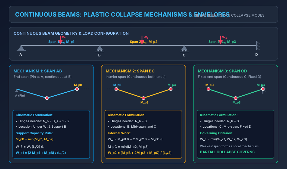
Continuous Beam Plastic Collapse Envelopes

6.1 The Support Plastic Hinge Matching Rule

At an intermediate support (e.g., support B) where Span 1 (with capacity Mp1M_{p1}) meets Span 2 (with capacity Mp2M_{p2}):

  • A plastic hinge will form in the weaker of the two adjoining members.
  • Therefore, the effective plastic moment capacity resisting rotation over support B is strictly: MpB=min⁡(Mp1,Mp2)\mathbf{M_{pB} = \min(M_{p1}, M_{p2})}

6.2 The Span-by-Span Partial Collapse Theorem

In any continuous beam resting on multiple supports, each span can collapse independently as a local mechanism:

  1. End Span (Pin at exterior support, continuous over interior support): Requires 2 plastic hinges (one in span, one over interior support): Wc,end=2Mp,span+Mp,interiorLspan/2(for central point load)W_{c,\text{end}} = \frac{2 M_{p,\text{span}} + M_{p,\text{interior}}}{L_{\text{span}} / 2} \quad (\text{for central point load})
  2. Interior Span (Continuous over both interior supports): Requires 3 plastic hinges (one at left support, one in span, one at right support): Wc,int=Mp,left+2Mp,span+Mp,rightLspan/2(for central point load)W_{c,\text{int}} = \frac{M_{p,\text{left}} + 2 M_{p,\text{span}} + M_{p,\text{right}}}{L_{\text{span}} / 2} \quad (\text{for central point load})
  3. Governing Structure Collapse Load: The entire continuous beam reaches collapse when the weakest span forms its local mechanism: Wc=min⁡(Wc,span 1,Wc,span 2,…,Wc,span N)\mathbf{W_c = \min \left( W_{c,\text{span 1}}, W_{c,\text{span 2}}, \dots, W_{c,\text{span } N} \right)}

6.3 Overhang Interactions

When a continuous beam has an overhang beyond an exterior support carrying a load PoverhangP_{\text{overhang}} at cantilever distance LohL_{\text{oh}}:

  • The overhang statically produces a definite hogging moment over the support: Msupport=Poverhang⋅LohM_{\text{support}} = P_{\text{overhang}} \cdot L_{\text{oh}}
  • If Msupport<Mp,spanM_{\text{support}} < M_{p,\text{span}}, the support moment acts as a constant known negative boundary moment that reduces the net sagging moment in the adjacent span.
  • If Poverhang⋅Loh≥Mp,spanP_{\text{overhang}} \cdot L_{\text{oh}} \ge M_{p,\text{span}}, a plastic hinge forms over the support directly under the overhang, converting the adjacent span into a simply supported beam!

7. Worked Numerical Examples

Problem 1: Propped Cantilever under UDL (Exact Hinge Location & Statics Verification)

Statement: A propped cantilever beam AB has span L=6.0 mL = 6.0\text{ m} and uniform plastic moment capacity Mp=90.0 kNmM_p = 90.0\text{ kNm}. The beam is fixed at A and supported on a roller prop at B. It carries a uniformly distributed load ww over its entire span.

  1. Determine the exact position of the sagging plastic hinge from the roller prop B and from fixed end A.
  2. Calculate the plastic collapse load wcw_c.
  3. Compute the vertical reaction at roller prop B (RBR_B) at collapse.
  4. Using statics, verify that the bending moment at the derived hinge location is exactly equal to MpM_p and that the shear force is zero.

Solution:

Step 1: Location of Sagging Plastic Hinge Using the derived optimization formula for a propped cantilever under UDL:

x=(2−1)L=(2−1)×6.0=0.41421356×6.0=2.48528 m (from roller prop B)x = (\sqrt{2} - 1) L = (\sqrt{2} - 1) \times 6.0 = 0.41421356 \times 6.0 = \mathbf{2.48528\text{ m \quad (from roller prop B)}}

Distance from fixed end A:

L−x=6.0−2.48528=3.51472 m (from fixed end A)L - x = 6.0 - 2.48528 = \mathbf{3.51472\text{ m \quad (from fixed end A)}}

Step 2: Plastic Collapse Load (wcw_c) Using the exact collapse formula:

wc=(6+42)MpL2=(6+4×1.41421356)×90.06.02w_c = \frac{(6 + 4\sqrt{2}) M_p}{L^2} = \frac{(6 + 4 \times 1.41421356) \times 90.0}{6.0^2} wc=(6+5.656854)×90.036.0=11.656854×90.036.0=11.656854×2.5=29.1421 kN/mw_c = \frac{(6 + 5.656854) \times 90.0}{36.0} = \frac{11.656854 \times 90.0}{36.0} = 11.656854 \times 2.5 = \mathbf{29.1421\text{ kN/m}}

Step 3: Vertical Reaction at Prop B (RBR_B) At collapse, the shear force at the sagging plastic hinge C is zero (VC=0V_C = 0):

VC=RB−wcx=0  ⟹  RB=wc⋅xV_C = R_B - w_c x = 0 \implies R_B = w_c \cdot x RB=29.142135×2.485281=72.4264 kNR_B = 29.142135 \times 2.485281 = \mathbf{72.4264\text{ kN}}

Step 4: Statics Verification of Moment and Yield Condition Consider segment CB from prop B to hinge C (x=2.48528 mx = 2.48528\text{ m}):

MC=RB⋅x−wcx22=(72.4264×2.48528)−29.142135×2.4852822M_C = R_B \cdot x - \frac{w_c x^2}{2} = (72.4264 \times 2.48528) - \frac{29.142135 \times 2.48528^2}{2} MC=180.0000−29.142135×6.176622=180.0000−90.0000=90.0000 kNmM_C = 180.0000 - \frac{29.142135 \times 6.17662}{2} = 180.0000 - 90.0000 = \mathbf{90.0000\text{ kNm}} MC=Mp=90.0 kNm(Exactly verified!)M_C = M_p = 90.0\text{ kNm} \quad \text{(Exactly verified!)}

Now check fixed end A (z=L−x=3.51472 mz = L - x = 3.51472\text{ m}): Total vertical load on beam: Wtotal=wc⋅L=29.142135×6.0=174.8528 kNW_{\text{total}} = w_c \cdot L = 29.142135 \times 6.0 = 174.8528\text{ kN}. Reaction at fixed end A: RA=Wtotal−RB=174.8528−72.4264=102.4264 kNR_A = W_{\text{total}} - R_B = 174.8528 - 72.4264 = 102.4264\text{ kN}. Moment at fixed end A:

MA=RB⋅L−wcL22+Mp=(72.4264×6.0)−(29.142135×18.0)=434.5584−524.5584=−90.0000 kNmM_A = R_B \cdot L - \frac{w_c L^2}{2} + M_p = (72.4264 \times 6.0) - (29.142135 \times 18.0) = 434.5584 - 524.5584 = -90.0000\text{ kNm} ∣MA∣=Mp=90.0 kNm(Hogging hinge fully verified!)|M_A| = M_p = 90.0\text{ kNm} \quad \text{(Hogging hinge fully verified!)}

Both hinges operate at exactly Mp=90.0 kNmM_p = 90.0\text{ kNm} and equilibrium is 100% satisfied.


Problem 2: Fixed Beam with Non-Uniform Capacities under Two Point Loads

Statement: A fixed-ended beam AB of span L=8.0 mL = 8.0\text{ m} has non-uniform plastic moment capacities:

  • Hogging capacity at supports: Mp1=150.0 kNmM_{p1} = 150.0\text{ kNm}.
  • Sagging capacity in the span: Mp2=100.0 kNmM_{p2} = 100.0\text{ kNm}. Two equal point loads WW are placed at the third points (x=L/3=2.6667 mx = L/3 = 2.6667\text{ m} and x=2L/3=5.3333 mx = 2L/3 = 5.3333\text{ m}). Determine the collapse load WcW_c.
               W                      W
               |                      |
               v                      v
      A--------+----------------------+--------B
    /|/|/      C                      D       /|/|/
    Fixed   (2.667m)      (2.667m)    (2.667m) Fixed
     Mp1 = 150 kNm     Mp2 = 100 kNm    Mp1 = 150 kNm

Solution:

Step 1: Mechanism Identification Between loads C and D, the shear force is zero, producing pure bending with a constant maximum sagging moment M(x)=Mp2M(x) = M_{p2}. A mechanism forms where:

  • Segment AC rotates by θ\theta about fixed support A.
  • Segment BD rotates by θ\theta about fixed support B.
  • Segment CD translates downward uniformly by deflection Δ=L3θ\Delta = \frac{L}{3} \theta.
  • Plastic hinges form at support A (Mp1M_{p1}), at C (Mp2M_{p2}), at D (Mp2M_{p2}), and at support B (Mp1M_{p1}).

Step 2: External Virtual Work (WEW_E) Both loads move down by the same vertical distance Δ=L3θ\Delta = \frac{L}{3} \theta:

WE=W⋅Δ+W⋅Δ=2WΔ=2W(L3θ)=23WLθW_E = W \cdot \Delta + W \cdot \Delta = 2 W \Delta = 2 W \left( \frac{L}{3} \theta \right) = \frac{2}{3} W L \theta

Step 3: Internal Plastic Work (WIW_I)

  • Hinge at A: Mp1θM_{p1} \theta
  • Hinge at C: Mp2θM_{p2} \theta
  • Hinge at D: Mp2θM_{p2} \theta
  • Hinge at B: Mp1θM_{p1} \theta
WI=Mp1θ+Mp2θ+Mp2θ+Mp1θ=2(Mp1+Mp2)θW_I = M_{p1} \theta + M_{p2} \theta + M_{p2} \theta + M_{p1} \theta = 2 (M_{p1} + M_{p2}) \theta

Step 4: Equating WE=WIW_E = W_I

23WcLθ=2(Mp1+Mp2)θ\frac{2}{3} W_c L \theta = 2 (M_{p1} + M_{p2}) \theta Wc=2(Mp1+Mp2)23L=3(Mp1+Mp2)LW_c = \frac{2 (M_{p1} + M_{p2})}{\frac{2}{3} L} = \mathbf{\frac{3 (M_{p1} + M_{p2})}{L}}

Substitute numerical values (Mp1=150.0 kNm,Mp2=100.0 kNm,L=8.0 mM_{p1} = 150.0\text{ kNm}, M_{p2} = 100.0\text{ kNm}, L = 8.0\text{ m}):

Wc=3×(150.0+100.0)8.0=3×250.08.0=750.08.0=93.7500 kNW_c = \frac{3 \times (150.0 + 100.0)}{8.0} = \frac{3 \times 250.0}{8.0} = \frac{750.0}{8.0} = \mathbf{93.7500\text{ kN}}

Problem 3: Three-Span Continuous Beam with Variable Sections and Overhang

Statement: A continuous beam ABCD with an overhang DE is supported on a simple pin at A, and rollers at B, C, and D:

  • Span AB: L1=5.0 m,Mp1=80.0 kNmL_1 = 5.0\text{ m}, M_{p1} = 80.0\text{ kNm}, carrying central point load W1=WW_1 = W.
  • Span BC: L2=6.0 m,Mp2=120.0 kNmL_2 = 6.0\text{ m}, M_{p2} = 120.0\text{ kNm}, carrying central point load W2=1.6WW_2 = 1.6 W.
  • Span CD: L3=4.0 m,Mp3=70.0 kNmL_3 = 4.0\text{ m}, M_{p3} = 70.0\text{ kNm}, carrying a dead load UDL w=20.0 kN/mw = 20.0\text{ kN/m}.
  • Overhang DE: L4=1.5 mL_4 = 1.5\text{ m}, carrying a concentrated tip load P=40.0 kNP = 40.0\text{ kN}. Determine the critical collapse load WcW_c and identify which span mechanism governs.

Solution:

Step 1: Intermediate Support Plastic Capacities

  • Support B: Intersection of Span 1 (Mp1=80 kNmM_{p1} = 80\text{ kNm}) and Span 2 (Mp2=120 kNmM_{p2} = 120\text{ kNm}): MpB=min⁡(80.0,120.0)=80.0 kNmM_{pB} = \min(80.0, 120.0) = \mathbf{80.0\text{ kNm}}
  • Support C: Intersection of Span 2 (Mp2=120 kNmM_{p2} = 120\text{ kNm}) and Span 3 (Mp3=70 kNmM_{p3} = 70\text{ kNm}): MpC=min⁡(120.0,70.0)=70.0 kNmM_{pC} = \min(120.0, 70.0) = \mathbf{70.0\text{ kNm}}
  • Support D: Overhang moment from tip load P=40 kNP = 40\text{ kN} at 1.5 m1.5\text{ m}: MD=P⋅L4=40.0×1.5=60.0 kNmM_D = P \cdot L_4 = 40.0 \times 1.5 = 60.0\text{ kNm} Since MD=60.0 kNm<Mp3=70.0 kNmM_D = 60.0\text{ kNm} < M_{p3} = 70.0\text{ kNm}, no plastic hinge forms at D. The cantilever provides a known constant hogging moment MD=60.0 kNmM_D = 60.0\text{ kNm}.

Step 2: Independent Mechanism 1 — Collapse of Span AB

  • Span AB is pinned at A and continuous at B.
  • Hinges form under load W1W_1 and at support B: WE=W1⋅(L12θ1)=W⋅(2.5θ1)W_E = W_1 \cdot \left(\frac{L_1}{2} \theta_1\right) = W \cdot (2.5 \theta_1) WI=Mp1(2θ1)+MpB(θ1)=(80.0×2θ1)+(80.0×θ1)=240.0θ1W_I = M_{p1} (2\theta_1) + M_{pB} (\theta_1) = (80.0 \times 2\theta_1) + (80.0 \times \theta_1) = 240.0 \theta_1 2.5Wθ1=240.0θ1  ⟹  Wc1=240.02.5=96.0000 kN2.5 W \theta_1 = 240.0 \theta_1 \implies W_{c1} = \frac{240.0}{2.5} = \mathbf{96.0000\text{ kN}}

Step 3: Independent Mechanism 2 — Collapse of Span BC

  • Span BC is continuous over both supports B and C.
  • Hinges form at support B, under load W2W_2 at mid-span, and at support C: WE=W2⋅(L22θ2)=(1.6W)⋅(3.0θ2)=4.8Wθ2W_E = W_2 \cdot \left(\frac{L_2}{2} \theta_2\right) = (1.6 W) \cdot (3.0 \theta_2) = 4.8 W \theta_2 WI=MpB(θ2)+Mp2(2θ2)+MpC(θ2)=80.0(θ2)+120.0(2θ2)+70.0(θ2)W_I = M_{pB} (\theta_2) + M_{p2} (2\theta_2) + M_{pC} (\theta_2) = 80.0(\theta_2) + 120.0(2\theta_2) + 70.0(\theta_2) WI=(80.0+240.0+70.0)θ2=390.0θ2W_I = (80.0 + 240.0 + 70.0) \theta_2 = 390.0 \theta_2 4.8Wθ2=390.0θ2  ⟹  Wc2=390.04.8=81.2500 kN4.8 W \theta_2 = 390.0 \theta_2 \implies W_{c2} = \frac{390.0}{4.8} = \mathbf{81.2500\text{ kN}}

Step 4: Governing Collapse Load & Behavior Comparing the two mechanisms:

Wc=min⁡(Wc1,Wc2)=min⁡(96.0000 kN,81.2500 kN)=81.2500 kNW_c = \min(W_{c1}, W_{c2}) = \min(96.0000\text{ kN}, 81.2500\text{ kN}) = \mathbf{81.2500\text{ kN}}
  • Governing Mode: Span BC collapses first at Wc=81.25 kNW_c = 81.25\text{ kN}.
  • Loads at collapse:
    • Load on Span AB: W1=81.25 kNW_1 = 81.25\text{ kN} (operating at 84.6%84.6\% of its capacity).
    • Load on Span BC: W2=1.6×81.25=130.0 kNW_2 = 1.6 \times 81.25 = 130.0\text{ kN} (100%100\% capacity, full collapse mechanism).
    • This demonstrates Partial Plastic Collapse, where catastrophic failure occurs in an interior bay while adjacent spans remain structurally sound.

8. Common Misconceptions & Exam Pitfalls

[!CAUTION]

  1. UDL Hinge Location in Propped Cantilever: The span plastic hinge does not form at mid-span (0.5L0.5L). It forms at x=(2−1)L≈0.4142Lx = (\sqrt{2} - 1) L \approx 0.4142 L from the roller prop. Assuming x=0.5Lx = 0.5L gives w=12Mp/L2w = 12 M_p / L^2, which violates the upper bound theorem (it overestimates capacity by 2.94%2.94\%).
  2. Hinge at Roller / Simple Pin: Simple pins and rollers transmit zero bending moment (M=0M = 0). They never develop a plastic hinge. Adding MpθM_p \theta at an exterior roller/pin support is a fatal error in plastic analysis.
  3. Interior Support Capacity Matching: At an interior support where section size changes, the hinge forms in the member with smaller capacity. Always take Mp=min⁡(Mp,left,Mp,right)M_p = \min(M_{p,\text{left}}, M_{p,\text{right}}).
  4. Fixed Beam under Point Load vs UDL:
    • Point load: Wc=8Mp/LW_c = 8 M_p / L.
    • UDL: wc=16Mp/L2w_c = 16 M_p / L^2 (total load Wc=16Mp/LW_c = 16 M_p / L). Notice that under UDL, the total collapse load is double that under a central concentrated load!

9. Comparative Summary & Master Formula Matrix

Boundary Condition Load Type Collapse Load Formula (WcW_c or wcw_c) Number of Hinges (NhN_h) Span Hinge Location
Simply Supported Mid-span Point Load Wc=4Mp/LW_c = 4 M_p / L 1 Mid-span (0.50L0.50 L)
Simply Supported UDL wc=8Mp/L2w_c = 8 M_p / L^2 1 Mid-span (0.50L0.50 L)
Propped Cantilever Mid-span Point Load Wc=6Mp/LW_c = 6 M_p / L 2 Mid-span (0.50L0.50 L)
Propped Cantilever Point Load at a,ba, b Wc=Mp(L+b)abW_c = \frac{M_p(L+b)}{ab} 2 Under load (aa from fixed end)
Propped Cantilever UDL wc=(6+42)MpL2≈11.6569MpL2w_c = \frac{(6+4\sqrt{2})M_p}{L^2} \approx 11.6569 \frac{M_p}{L^2} 2 x=0.4142Lx = 0.4142 L from prop
Fixed-Fixed Mid-span Point Load Wc=8Mp/LW_c = 8 M_p / L 3 Mid-span (0.50L0.50 L)
Fixed-Fixed Point Load at a,ba, b Wc=2MpLabW_c = \frac{2 M_p L}{a b} 3 Under load
Fixed-Fixed UDL wc=16Mp/L2w_c = 16 M_p / L^2 3 Mid-span (0.50L0.50 L)
Fixed Non-Uniform Mid-span Point Load Wc=4(Mp1+Mp2)LW_c = \frac{4 (M_{p1} + M_{p2})}{L} 3 Mid-span (0.50L0.50 L)
Fixed Non-Uniform UDL wc=8(Mp1+Mp2)L2w_c = \frac{8 (M_{p1} + M_{p2})}{L^2} 3 Mid-span (0.50L0.50 L)

10. Practice Questions & Competitive Examination Problems

Multiple Choice & Objective Questions

  1. [GATE CE] A propped cantilever beam of span LL is subjected to a uniformly distributed load ww. The distance of the plastic hinge in the span from the simply supported prop is:

    • (A) 0.500L0.500 L
    • (B) 0.414L0.414 L
    • (C) 0.586L0.586 L
    • (D) 0.333L0.333 L
      Answer: (B) x=(2−1)L≈0.414Lx = (\sqrt{2}-1)L \approx 0.414 L.
  2. [ESE CE] A fixed beam of span LL and uniform plastic moment capacity MpM_p carries a central concentrated load WW. The collapse load is:

    • (A) 4Mp/L4 M_p / L
    • (B) 6Mp/L6 M_p / L
    • (C) 8Mp/L8 M_p / L
    • (D) 12Mp/L12 M_p / L
      Answer: (C) Wc=8Mp/LW_c = 8 M_p / L.
  3. [SSC JE] For a fixed beam subjected to a uniformly distributed load ww over the entire span LL, the plastic collapse load wcw_c is:

    • (A) 8Mp/L28 M_p / L^2
    • (B) 11.66Mp/L211.66 M_p / L^2
    • (C) 16Mp/L216 M_p / L^2
    • (D) 24Mp/L224 M_p / L^2
      Answer: (C) wc=16Mp/L2w_c = 16 M_p / L^2.
  4. [State AE] In a two-span continuous beam ABC with equal spans LL and uniform MpM_p, carrying central point loads WW on both spans, the plastic collapse load is:

    • (A) 4Mp/L4 M_p / L
    • (B) 6Mp/L6 M_p / L
    • (C) 8Mp/L8 M_p / L
    • (D) 11.66Mp/L11.66 M_p / L
      Answer: (B) Each span behaves as a propped cantilever: Wc=6Mp/LW_c = 6 M_p / L.

11. References & Code Standards

  • IS 800:2007: General Construction in Steel — Code of Practice, Section 12 (Plastic Design), Bureau of Indian Standards.
  • AISC 360-16: Specification for Structural Steel Buildings, American Institute of Steel Construction.
  • Eurocode 3 (EN 1993-1-1): Design of Steel Structures — Part 1-1: General Rules and Rules for Buildings.
  • Neal, B. G. (1977). The Plastic Methods of Structural Analysis. Chapman and Hall.
  • Heyman, J. (1971). Plastic Design of Frames. Cambridge University Press.