Static Indeterminacy of Beams, Trusses & Rigid Frames (2D & 3D)
In this chapter (3 topics)
On this page
- Metadata
- 1. Engineering Fundamentals & Theoretical Basis
- 1.1 Equations of Static Equilibrium
- 1.2 Definition of Static Indeterminacy (Ds)
- 1.3 Decomposition: External (Dse) vs. Internal (Dsi) Indeterminacy
- 2. Mathematical Formulations & Rigorous Derivations
- 2.1 Statically Determinate and Indeterminate Beams (2D & 3D)
- 2.2 Pin-Jointed Trusses (2D & 3D)
- 2.3 Rigid-Jointed Frames (2D & 3D)
- 3. Engineering Visualizations & Technical Diagrams
- Diagram 1: Beam Indeterminacy & Internal Release Mechanisms
- Diagram 2: Truss & Rigid Frame Indeterminacy via Closed-Loop / Cut Method
- 4. Comprehensive Comparison Tables
- Table 1: Master Static Indeterminacy Formulas
- Table 2: Catalog of Internal Releases and Their Mathematical Conditions
- Table 3: Member-Joint Method vs. Closed-Loop Cut Method for 2D Frames
- 5. Fully Solved Numerical Examples
- Example 1: Multi-Span Continuous Beam with Multiple Releases
- Example 2: 2D Pin-Jointed Pratt Bridge Truss
- Example 3: Two-Bay, Two-Story Rigid Portal Frame
- 6. Common Misconceptions & High-Yield Exam Traps
- Misconception 1: "An internal hinge always provides rr = 1 additional equation"
- Misconception 2: "If Ds ≥ 0, the structure is guaranteed to be stable"
- Misconception 3: "Internal indeterminacy of a truss is m + r - 2j"
- Misconception 4: "Ground boundary does not count as a closed loop"
- Misconception 5: "Internal shear release eliminates all forces"
- 7. Previous Years Questions & Benchmark Solutions
- Question 1 (GATE CE)
- Question 2 (UPSC ESE)
- Question 3 (SSC JE / State AE)
- 8. Quick Revision Formulas & Key Exam Takeaways
Metadata
- Topic ID:
SA-01-01 - Module: Subject 03: Structural Analysis
- Chapter: Chapter 01: Determinacy, Indeterminacy & Stability of Structures
- Author: Civil Engineering Autonomous Content & QA Agent
- Standard Reference: IS 800:2007, IS 456:2000, SP 16, IRC:21
- Target Examinations: GATE CE, UPSC ESE, SSC JE, State AE/JE, RRB JE
1. Engineering Fundamentals & Theoretical Basis
In structural engineering, the analysis of any load-bearing skeleton begins with determining whether its internal member forces and external support reactions can be determined uniquely from the equations of static equilibrium alone.
1.1 Equations of Static Equilibrium
For a structure at rest in static equilibrium under external applied loads:
1. In Two Dimensions (2D / Plane Structures):
There are 3 independent equations of global equilibrium:
2. In Three Dimensions (3D / Space Structures):
There are 6 independent equations of global equilibrium:
1.2 Definition of Static Indeterminacy ()
A structure is defined as statically indeterminate (or hyperstatic) if the number of unknown forces (support reactions plus internal member forces) exceeds the total number of independent static equilibrium equations available. The excess number of unknown forces is termed the Degree of Static Indeterminacy () or Degree of Redundancy.
- Statically Determinate (): All reactions and internal forces are determined completely and uniquely using static equilibrium equations alone. Bending moments, shears, and axial forces are completely independent of cross-sectional dimensions () and material properties ().
- Statically Indeterminate (): Static equilibrium equations are insufficient. Additional compatibility equations based on deformations (elastic curve, slope-deflection, virtual work, or flexibility methods) are mandatory. Internal force distributions depend directly on relative member stiffnesses ().
- Unstable / Mechanism (): The structure lacks sufficient constraints to resist external loads, resulting in rigid-body motion or collapse.
1.3 Decomposition: External () vs. Internal () Indeterminacy
The total degree of static indeterminacy consists of two distinct physical components:
- Degree of External Static Indeterminacy ():
- Represents the redundancy in external support reactions.
- For a 2D structure: (where is total support reaction components).
- For a 3D structure: .
- If , the structure has more support reactions than required for overall equilibrium. Redundant reactions can be removed without causing immediate rigid-body collapse.
- Degree of Internal Static Indeterminacy ():
- Represents the redundancy in internal member forces when all external support reactions have already been solved or held fixed.
- Even if external reactions are known, closed loops in frames or redundant diagonal cross-braces in trusses prevent direct calculation of member forces using method of joints or sections alone.
2. Mathematical Formulations & Rigorous Derivations
2.1 Statically Determinate and Indeterminate Beams (2D & 3D)
In beams, loads are transmitted primarily via bending moments and transverse shears . Beams have open linear topologies (no closed loops), which means internal indeterminacy is zero (). Indeterminacy arises solely from external reactions and is reduced by internal releases.
Reactions (r) ────> [ BEAM STRUCTURE ] <──── Internal Releases (r_r)
1. Support Reaction Components ():
- Roller Support: Constrains translation perpendicular to the rolling plane (vertical force ).
- Pinned / Hinge Support: Constrains translations in two orthogonal directions ().
- Fixed / Clamped Support (2D): Constrains vertical translation, horizontal translation, and rotational curvature ().
- Guided Roller / Shear Sleeve (2D): Allows vertical translation but restrains horizontal translation and rotation ().
- Fixed Support (3D): Constrains 3 translations and 3 rotations ().
2. Internal Releases / Special Equations of Condition ():
An internal release is an engineered kinematic discontinuity that forces a specific internal stress resultant to vanish, providing an extra independent equilibrium equation:
- Internal Moment Hinge:
- Forces bending moment to zero at the hinge: .
- If two collinear beam members meet at the hinge: .
- General Multibar Rule: When distinct members meet at an internal hinge: (Proof: Setting the bending moment of members to zero automatically satisfies equilibrium of the joint for the remaining member).
- Internal Vertical Shear Release (Guided Sleeve):
- Allows relative vertical translation between adjacent segments, forcing transverse shear force to zero: .
- Bending moment and axial force are transmitted across the release.
- Internal Axial Force Release (Axial Slide / Roller Link):
- Allows longitudinal sliding, forcing axial thrust to zero: .
- Shear force and bending moment are transmitted across the release.
General Governing Formula for 2D Beams:
For 3D Beams:
2.2 Pin-Jointed Trusses (2D & 3D)
A pin-jointed truss is an ideal framework formed by straight bars connected at their ends by frictionless spherical pins (or frictionless cylindrical pins in 2D). Every member is a two-force member carrying only axial force (tension or compression).
   Unknowns:  m member forces + r reaction components
   Equations: 2 equilibrium equations per joint (2D) or 3 equations per joint (3D)
1. Two-Dimensional (Plane) Trusses:
- Number of unknown internal bar forces:
- Number of external reaction components:
- Total unknown forces:
- Number of joints:
- Number of equilibrium equations available: ( at each joint).
Total Degree of Static Indeterminacy:
Decomposition:
- External Static Indeterminacy:
- Internal Static Indeterminacy:
Physical Interpretation of Truss Internal Indeterminacy:
- (): Just-stiff, internally determinate truss. Members form a basic non-deformable triangulated network.
- (): Over-stiff, internally indeterminate truss. Redundant bars (such as counter-diagonal braces) exist. If a redundant bar is fabricated too short by , initial assembly induces self-equilibrating pretension stresses throughout the truss even without external loads.
- (): Under-stiff, deficient truss. The framework is not rigid and constitutes an unstable kinematic mechanism.
2. Three-Dimensional (Space) Trusses:
At each 3D spherical pin joint, 3 equilibrium equations exist (). Overall global equilibrium provides 6 equations.
- External Indeterminacy:
- Internal Indeterminacy:
2.3 Rigid-Jointed Frames (2D & 3D)
In rigid-jointed frames, members are rigidly welded or monolithically cast at joints. When the frame deforms, all member ends meeting at a rigid joint rotate through identical angles (), preserving the original joint angle. Each member transmits 3 internal force components in 2D (Axial , Shear , Moment ) and 6 internal force components in 3D ().
                ┌──────────────────────────────────────┐
                │ METHODS FOR RIGID FRAME INDETERMINACY│
                └──────────────────┬───────────────────┘
                                   │
         ┌─────────────────────────┴─────────────────────────┐
         ▼                                                   ▼
  [ METHOD 1: MEMBER-JOINT ]                          [ METHOD 2: CLOSED LOOP / CUT ]
  Ds = (3m + r) - (3j + rr)                           Ds = 3C - rr - r_rel,supp
Method 1: The Member-Joint Formula
- In 2D, each member has 3 unknown internal actions: total internal forces.
- Adding external reactions gives total unknowns .
- Each rigid joint provides 3 equations of joint equilibrium (): total equations.
- Any internal release adds extra equations.
Total Degree of Static Indeterminacy for 2D Rigid Frames:
For 3D Rigid Space Frames:
Method 2: The Closed-Loop (Tree / Cut) Method
The Member-Joint formula can be time-consuming for large multi-story, multi-bay frames because counting dozens of members and joints invites bookkeeping errors. The Closed-Loop / Cut Method provides an instant, error-free shortcut.
Theoretical Basis:
An open, branched structural cantilever rooted at a single fixed support has no closed loops and is completely statically determinate (). Every closed loop (or closed ring cell) in a 2D frame introduces 3 internal redundant forces (1 axial, 1 shear, 1 bending moment). Making a conceptual cut across one member of a closed cell exposes these 3 redundants and opens the cell.
       ┌───────┐
       │   C   │  ====>  Make 1 Cut  ====>  Exposes 3 Unknowns (P, V, M)
       └───────┘                            Cell is now open & determinate
Formulation with Ground as Base Boundary:
When the foundation between supports is considered as the bottom closing boundary of the ground story:
- Let be the total number of closed cells/loops (including loops bounded by the ground between foundation supports).
- For a frame with all supports fully fixed ( each), every cell cut removes 3 redundants:
- If any support is non-fixed (e.g., pinned or roller), the support provides fewer reactions than a fixed base (). These missing restraints act as support releases ():
- If internal releases (moment hinges, shear releases) exist within the framework, they reduce indeterminacy by .
Therefore, the Universal Closed-Loop Formula for 2D Frames is:
For 3D Space Frames:
Alternative Formulation (Using External Indeterminacy ):
If we only count the internal member cells above the ground (), then the ground loops are handled by external redundancy:
Both closed-loop formulations yield identical results and agree with the Member-Joint formula.
3. Engineering Visualizations & Technical Diagrams
Diagram 1: Beam Indeterminacy & Internal Release Mechanisms
The diagram below details standard beam support conditions, reaction counts, and the four fundamental internal release types.
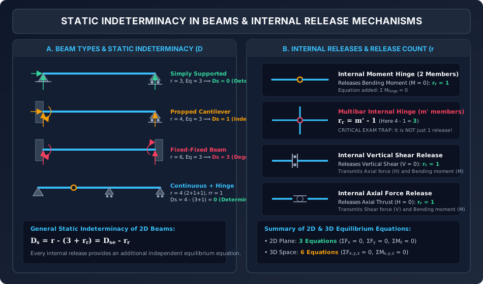
Analytical Walk-Through:
- Beam Classification (Panel A): Displays the progression of static indeterminacy from simply supported (), to propped cantilever (), fixed-fixed (), and a multi-span continuous beam with an internal hinge ().
- Internal Releases (Panel B): Details how each release type eliminates specific internal stress resultants:
- Simple hinge ().
- Multibar hinge with branches ().
- Guided sleeve vertical shear release ().
- Axial sliding sleeve ().
Diagram 2: Truss & Rigid Frame Indeterminacy via Closed-Loop / Cut Method
The figure below compares the internal/external decomposition of a 2D pin-jointed truss with the closed-loop cut method applied to a multi-story, multi-bay rigid frame.
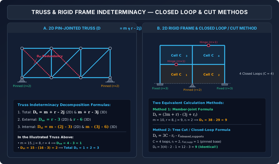
Analytical Walk-Through:
- Truss Decomposition (Panel A): A 3-bay Pratt truss () illustrates external redundancy () from two pinned supports and internal redundancy () from cross-bracing.
- Rigid Frame Closed Loops (Panel B): A 2-bay, 2-story portal frame with 4 closed cells demonstrates both the member-joint formula () and the closed-loop cut formula ().
4. Comprehensive Comparison Tables
Table 1: Master Static Indeterminacy Formulas
| Structural Type | Plane (2D) Structures | Space (3D) Structures | Primary Redundants |
|---|---|---|---|
| Beams | Support reactions () | ||
| Pin-Jointed Trusses | Bar axial forces () | ||
| Rigid-Jointed Frames | Bending moments, shears, axial thrusts | ||
| Composite Frames (Hybrid) | Mixed frame actions |
Table 2: Catalog of Internal Releases and Their Mathematical Conditions
| Release Type | Kinematic Discontinuity | Stress Resultant Released | Additional Equations Added () | Transmitted Actions |
|---|---|---|---|---|
| Internal Pin / Moment Hinge | Relative rotation () | Bending moment | ( for 2 bars) | Axial Force (), Shear Force () |
| Vertical Shear Release (Sleeve) | Relative vertical slide () | Shear force | Axial Force (), Bending Moment () | |
| Axial Slide / Roller Link | Relative axial slide () | Axial force | Shear Force (), Bending Moment () | |
| Complete Free Joint | Complete separation | All 3 forces () | None | |
| 3D Spherical Ball Joint | 3 independent relative rotations | 3 moments () | 3 Forces () | |
| 3D Cylindrical Pin Joint | 1 relative rotation about pin axis | 1 moment component () | 3 Forces, 2 Moments |
Table 3: Member-Joint Method vs. Closed-Loop Cut Method for 2D Frames
| Evaluation Metric | Member-Joint Method: | Closed-Loop Cut Method: |
|---|---|---|
| Speed in Competitive Exams | Moderate (prone to member/joint counting slips in multi-story frames) | Extremely Fast (count closed boxes at a glance) |
| Applicability to Trusses | Direct () | Not recommended (truss bars carry only 1 force, not 3) |
| Handling Non-Fixed Bases | Natural (simply sum actual reactions ) | Subtract support releases: for each base |
| Visual Error Checking | Difficult | Instantaneous (every cut makes a visible tree branch) |
5. Fully Solved Numerical Examples
Example 1: Multi-Span Continuous Beam with Multiple Releases
Problem Statement:
Determine the degree of static indeterminacy () and classify the stability of the continuous bridge girder shown below:
- Support : Fully fixed support ().
- Support : Roller support ().
- Support : Pinned support (). At joint , an additional vertical cantilever column arm meets the continuous beam ( members meet at joint ). Joint has an internal pin hinge connecting all 3 members.
- Support : Roller support ().
- Span contains an internal moment hinge connecting 2 beam segments.
- Span contains a guided vertical shear release.
Step 1: Count Total External Support Reactions ()
External Indeterminacy:
Step 2: Evaluate All Internal Releases ()
- Internal moment hinge in span connecting members:
- Multibar moment hinge at support where members meet (span , span , and vertical arm):
- Guided vertical shear release in span :
Total additional independent equilibrium equations provided by releases:
Step 3: Compute Overall Degree of Static Indeterminacy ()
Conclusion: The girder has degree of static indeterminacy . It is statically determinate and can be solved completely using statics alone!
Example 2: 2D Pin-Jointed Pratt Bridge Truss
Problem Statement:
A plane highway truss spans with equal bays of each and a depth of .
- The bottom chord has panel points ().
- The top chord has panel points ().
- Both left support () and right support () are pinned to rigid masonry abutments ().
- Bays and contain diagonal cross-braces (two intersecting diagonals in each bay).
- Bay contains a single diagonal tension brace.
Calculate:
- Total number of members and joints .
- External static indeterminacy .
- Internal static indeterminacy .
- Total static indeterminacy .
Step 1: Member and Joint Inventory
- Number of joints:
- Member count:
- Bottom chord: members
- Top chord: members
- Vertical posts: members ()
- Diagonals:
- Bay 1 (cross-braced): members
- Bay 2 (cross-braced): members
- Bay 3 (single diagonal): member
- Total members:
- Support reactions:
Step 2: Compute Indeterminacies
- External Indeterminacy (): (The second horizontal reaction is redundant).
- Internal Indeterminacy (): (The two extra counter-diagonals in Bays 1 and 2 create 2 internal redundancies).
- Total Static Indeterminacy ():
Check decomposition:
Example 3: Two-Bay, Two-Story Rigid Portal Frame
Problem Statement:
A two-bay, two-story steel building portal frame is shown in Diagram 2 (Panel B).
- The foundation has column bases:
- Base : Fixed support ()
- Base : Pinned support ()
- Base : Fixed support ()
- First story beam has an internal pin hinge at midspan ().
- Roof story beam has an internal pin hinge at midspan ().
Determine the degree of static indeterminacy () using:
- Method 1: The Member-Joint Formula.
- Method 2: The Closed-Loop / Tree Cut Method. Verify that both methods give identical results.
Method 1: Member-Joint Formula
- Member count ():
- Story 1 columns:
- Story 2 columns:
- Floor 1 beams:
- Roof beams:
- Total members:
- Joint count ():
- Base joints: ()
- Floor 1 joints: ()
- Roof joints: ()
- Total joints:
- Total reactions ():
- Internal releases ():
Compute :
Method 2: Closed-Loop / Tree Cut Method
- Count the closed cells ():
- Floor 2 (Roof): bay cells ().
- Floor 1 (Ground story closed by foundation between and ): bay cells ().
- Total closed loops: .
- Support release count ():
- Supports: .
- A fully fixed baseline would have reactions.
- Actual reactions .
- Support release: (due to pinned base at ).
- Internal releases:
Compute :
Alternative Tree Cut Verification:
To convert the frame into a determinate, stable open cantilever tree:
- Base is kept as the single fixed root ().
- Remove support (release 2 reactions).
- Remove support (release 3 reactions).
- Make 1 cut in beam (releases 3 internal forces).
- Make 1 cut in beam (releases 3 internal forces).
- Make 1 cut in beam (releases 3 internal forces).
- Make 1 cut in beam (releases 3 internal forces).
- Sum of released redundants .
- Deduct the internal hinges which relax the structure: .
- Deduct the 6 global equations from cut branches: .
Result: Both the Member-Joint formula and the Closed-Loop method confirm .
6. Common Misconceptions & High-Yield Exam Traps
Misconception 1: "An internal hinge always provides additional equation"
- The Trap: When 3 or 4 members meet at a single hinge, students write .
- Correction: The number of independent equilibrium equations added by an internal hinge is: where is the number of members meeting at that hinge. If beams meet at an internal pin, , NOT !
Misconception 2: "If , the structure is guaranteed to be stable"
- The Trap: Concluding that any structure with is stable and statically determinate.
- Correction: is a necessary but NOT sufficient condition for stability! A structure can have and still be an unstable kinematic mechanism if:
- All reactions are parallel (resists no transverse load).
- All reactions are concurrent at a single point (resists no moment about that point).
- Three internal hinges are placed in a straight line (creates an unstable toggle mechanism).
Misconception 3: "Internal indeterminacy of a truss is "
- The Trap: Confusing total indeterminacy with internal indeterminacy .
- Correction: Total indeterminacy is . Internal indeterminacy is: A truss can be externally indeterminate () while remaining internally determinate ().
Misconception 4: "Ground boundary does not count as a closed loop"
- The Trap: When applying , students only count the top floor cells and ignore the ground story cells.
- Correction: The foundation between fixed supports provides infinite rigid connectivity, closing the lower bays. A 1-story, 1-bay fixed portal frame has closed loop formed by Left Column + Beam + Right Column + Ground, giving .
Misconception 5: "Internal shear release eliminates all forces"
- The Trap: Treating a guided shear sleeve like an open cut that transmits nothing.
- Correction: A shear release eliminates only transverse shear (). It transmits full axial force () and full bending moment () across the joint.
7. Previous Years Questions & Benchmark Solutions
Question 1 (GATE CE)
Problem: The degree of static indeterminacy () of the 2D rigid portal frame shown below, having a fixed base at the left column, a roller support at the right column, and an internal moment hinge at midspan of the beam is:
(A)
(B)
(C)
(D)
Solution:
- Reactions:
- Left base (fixed): ()
- Right base (roller): ()
- Total reactions:
- Closed cells:
- 1 bay, 1 story:
- Support releases:
- Fixed base: releases
- Roller base: releases
- Internal release:
- 1 hinge on beam:
- Compute :
Check via Member-Joint formula:
- (2 columns, 1 beam)
- (2 bases, 2 eaves)
- ,
Correct Answer: (A) 0 (Statically Determinate).
Question 2 (UPSC ESE)
Problem: A pin-jointed plane truss has members, joints, and external reaction components. If , the truss is:
(A) Statically determinate and stable
(B) Statically indeterminate
(C) An unstable mechanism
(D) Statically determinate but internally unstable
Solution: For a 2D pin-jointed truss, total static indeterminacy is:
If , then . The number of available equilibrium equations () exceeds the available resisting forces (). The structure lacks sufficient constraints and is geometrically an unstable mechanism.
Correct Answer: (C) An unstable mechanism.
Question 3 (SSC JE / State AE)
Problem: What is the degree of external static indeterminacy of a propped cantilever beam with an internal hinge located at of the span from the fixed end?
(A)
(B)
(C)
(D)
Solution:
- Propped cantilever has 1 fixed support () and 1 roller support ().
- Total external reactions: .
- By definition, external static indeterminacy depends ONLY on external support reactions relative to basic 2D rigid-body equilibrium equations ( equations):
(Note: The internal hinge provides an internal condition that reduces overall to , but the external support redundancy remains ).
Correct Answer: (B) 1.
8. Quick Revision Formulas & Key Exam Takeaways
╔═══════════════════════════════════════════════════════════════════════════════╗
║                  STATIC INDETERMINACY FORMULA CHEAT SHEET                     ║
╠═══════════════════════════════════════════════════════════════════════════════╣
║ 1. General Relation:                                                          ║
║    Ds = Dse + Dsi                                                             ║
║    • 2D External:  Dse = r - 3                                                ║
║    • 3D External:  Dse = r - 6                                                ║
║                                                                               ║
║ 2. Beams:                                                                     ║
║    • 2D Beams:  Ds = r - (3 + rr)                                             ║
║    • 3D Beams:  Ds = r - (6 + rr)                                             ║
║                                                                               ║
║ 3. Pin-Jointed Trusses:                                                       ║
║    • 2D Plane:   Ds = m + r - 2j                                              ║
║                  Dse = r - 3,   Dsi = m - (2j - 3)                            ║
║    • 3D Space:   Ds = m + r - 3j                                              ║
║                  Dse = r - 6,   Dsi = m - (3j - 6)                            ║
║                                                                               ║
║ 4. Rigid-Jointed Frames:                                                      ║
║    • Member-Joint Method (2D): Ds = (3m + r) - (3j + rr)                      ║
║    • Member-Joint Method (3D): Ds = (6m + r) - (6j + rr)                      ║
║    • Closed-Loop Cut Method (2D):                                             ║
║      Ds = 3C - rr - r_rel,supp                                                ║
║      where r_rel,supp = 3 N_supp - r  (0 for fixed, 1 for pin, 2 for roller)   ║
║      Ds = 3 C_internal + Dse - rr                                             ║
║                                                                               ║
║ 5. Internal Releases (rr):                                                    ║
║    • Moment hinge with m' branches:   rr = m' - 1   (m'=2 ⟹ rr=1)             ║
║    • Vertical shear release (sleeve): rr = 1        (V = 0)                   ║
║    • Axial force release (slide):     rr = 1        (N = 0)                   ║
║    • 3D spherical ball joint:         rr = 3        (Mx = My = Mz = 0)        ║
╚═══════════════════════════════════════════════════════════════════════════════╝