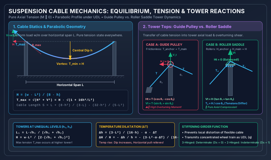
Suspension bridges represent the pinnacle of long-span structural engineering. While rigid beams and trusses resist gravity loads primarily through flexure and shear—requiring heavy cross-sections to resist bending moments—a cable is a structural tensile element of negligible flexural rigidity (EI≈0) and shear stiffness (GA≈0). Consequently, a cable carries external loads exclusively through pure axial tension (T), with bending moments and transverse shears identically zero everywhere along its length:
M(x)≡0,Q(x)≡0
Because tensile members do not suffer from compressive buckling or lateral-torsional instability, high-strength structural steel wires (tensile strength fu≈1600 to 1860 MPa) can be utilized at exceptionally high allowable stresses, enabling monumental clear spans exceeding 1000 to 2000 meters (e.g., Akashi Kaikyo Bridge, 1991 m; 1915 Çanakkale Bridge, 2023 m).
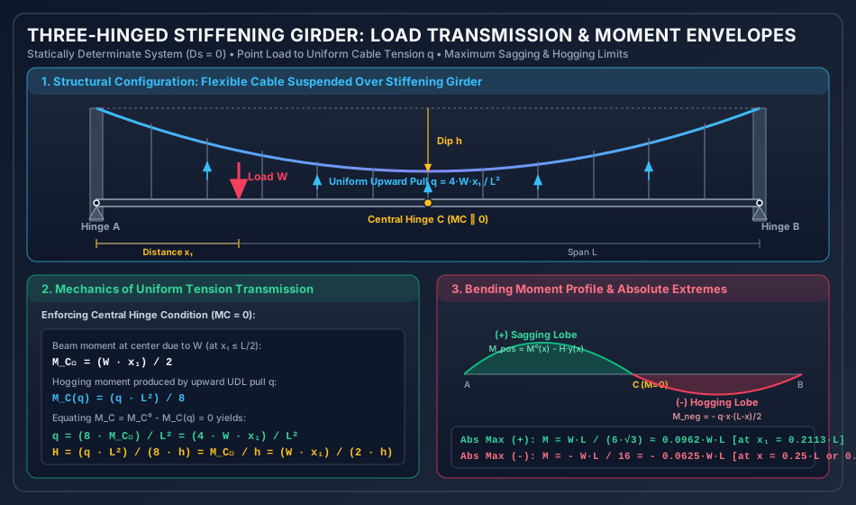
However, a raw, unstiffened cable is an extremely flexible kinematic mechanism: any localized concentrated live load causes severe local distortion and dramatic changes in cable geometry. To make suspension bridges serviceable for vehicular and railway traffic, a stiffening girder (or stiffening truss) is introduced. The stiffening girder distributes concentrated live loads into a substantially uniform upward tension (q) transmitted via vertical hangers to the main cable, thereby preserving the parabolic profile of the cable and limiting bridge slopes and deflections.
Point Load (W) on Deck ──> Stiffening Girder distributes load ──> Vertical Hangers carry uniform pull q ──> Main Cable carries pure tension (H)
2. Equilibrium & Profile of Flexible Cables
2.1 Fundamental Assumptions of Cable Mechanics
Perfect Flexibility: The cable offers no resistance to bending (EI=0) or shear (GA=0). Internal bending moment and shear force are zero at every section.
Inextensibility (in first-order statics): The cable axis does not change length under small loads (elastic stretch is considered as a secondary effect).
Tensile Only: The cable cannot resist compressive or torsional forces.
Smooth Loading Transfer: External loads are transferred via closely spaced vertical hangers, treated mathematically as a continuous line load.
2.2 Differential Equation of Cable Profile
Consider an infinitesimal cable element ds in equilibrium under an external distributed vertical load w(x) per unit horizontal length:
Horizontal equilibrium (ΣFx=0):
(T+dT)cos(θ+dθ)−Tcosθ=0⟹d(Tcosθ)=0
Therefore, the horizontal component of cable tension is constant throughout the entire span:
H=Tcosθ=constant
Dividing the vertical equilibrium equation by the horizontal constant H=Tcosθ:
Hd(Tsinθ)=Tcosθd(Tsinθ)=d(tanθ)=Hw(x)dx
Since the slope of the cable profile is tanθ=dxdy, differentiating with respect to x yields the governing differential equation of a flexible cable:
dx2d2y=Hw(x)
Integrating twice for a uniformly distributed horizontal load w(x)=w=constant:
dxdy=Hwx+C1y(x)=2Hwx2+C1x+C2
2.3 Parabolic vs. Catenary Profiles
Feature / Metric
Parabolic Cable
Catenary Cable
Load Distribution
Uniform per unit horizontal span (w kN/m)
Uniform per unit arc length (w0 kN/m of cable)
Governing Loading
Bridge deck & traffic dead/live load
Heavy cable self-weight hanging freely
Governing Equation
dx2d2y=Hw
dx2d2y=Hw01+(dy/dx)2
Profile Formula
y=2Hwx2ory=L24hx(L−x)
y=ccosh(cx)−c,c=w0H
Engineering Scope
Long-span suspension bridges with decks
Transmission power lines, guy wires, free mooring lines
Approximation Error
Exact for deck loads; accurate within 1% for h/L≤1/10
Exact for self-weight alone
3. Tension Resolution & Cable Length Formulations
3.1 Supports at the Same Elevation (hA=hB=h)
Let the cable span be L, central dip h, and uniformly distributed load w per unit horizontal span.
With origin at the left support A(0,0):
y(x)=L24hx(L−x)
Horizontal Tension (H):
At midspan (x=L/2), the vertical dip is y=h:
h=2Hw(L/2)2=8HwL2⟹H=8hwL2
Vertical Reactions (VA,VB):
By symmetry:
VA=VB=2wL
Tension at Any Point (Tx):Tx=H2+Vx2=Hsecθx
where Vx=2wL−wx is the vertical shear in the cable.
Minimum Tension (Tmin):
Occurs at the vertex (lowest point x=L/2), where the slope is zero (θ=0,Vx=0):
Tmin=H=8hwL2
Maximum Tension (Tmax):
Occurs at the supports (x=0 or x=L), where inclination θ and vertical reaction V are maximum:
tanθmax=dxdyx=0=L4hTmax=H2+VA2=H2+(2wL)2=H1+(wL2/8hwL/2)2=H1+L216h2
3.2 Supports at Different Elevations (h1=h2)
When towers have unequal heights, the lowest point (vertex O) is shifted horizontally toward the lower support.
Let h1 be the dip from the higher left support A, h2 be the dip from the lower right support B, and L be the total horizontal distance between supports (L=L1+L2).
Since the horizontal tension H is identical in both segments:
Absolute Maximum Tension:
Occurs at the higher support (A):
Tmax=H2+VA2=H2+(wL1)2
3.3 Cable Length Formulation (S)
The actual curved arc length S of the parabolic cable:
S=∫0Lds=∫0L1+(dxdy)2dx
Using the binomial series expansion 1+z2≈1+21z2−81z4:
S=∫0L[1+21(dxdy)2−81(dxdy)4]dx
Substituting dxdy=L24h(L−2x) and integrating:
S≈L+3L8h2−5L332h4
For typical suspension bridges (h/L≤1/10), the fourth-order term is negligibly small (<0.1%). Thus, the standard engineering formula is:
S≈L+3L8h2
4. Anchor Cables, Pulleys, and Roller Saddles on Towers
The main cable is supported at the tower tops and anchored to heavy concrete counterweights or bedrock via backstay (anchor) cables. The mechanism used at the tower top determines the forces transmitted to the tower piers.
4.1 Case A: Guide Pulley Support (Frictionless Sheave)
In this arrangement, the cable passes over a frictionless rotating pulley mounted at the top of the tower:
Cable Tension Equality: Because the pulley is frictionless, the tension in the anchor cable must equal the tension in the main cable:
Tanchor=Tmain=T
Horizontal Force on Tower Top (Htower):Htower=Tcosθ1−Tcosθ2=T(cosθ1−cosθ2)
If the anchor cable angle θ2 is steeper than the main cable angle θ1 (θ2>θ1), cosθ2<cosθ1, producing a net inward horizontal shear pushing the tower top toward the anchorage!
This horizontal shear induces enormous overturning bending moments along the height of the tall tower, requiring heavy, expensive pier design.
Vertical Axial Load on Tower (Vtower):Vtower=Tsinθ1+Tsinθ2=T(sinθ1+sinθ2)
4.2 Case B: Roller Saddle Support (Movable Bearing)
In modern long-span suspension bridges, the cable rests in a grooved steel saddle mounted on hardened steel rollers atop the tower:
Horizontal Equilibrium: Because the saddle is free to roll horizontally, it cannot sustain any horizontal shear force (Htower=0). The horizontal components of tension must be identical:
Hanchor=Hmain=HTanchorcosθ2=Tmaincosθ1=H
Anchor Cable Tension:Tanchor=cosθ2H=Hsecθ2=Tmain
Because θ2>θ1, cosθ2<cosθ1, which means the anchor cable carries higher tension than the main cable!
Vertical Axial Load on Tower (Vtower):Vtower=Tmainsinθ1+Tanchorsinθ2=Htanθ1+Htanθ2=H(tanθ1+tanθ2)
Engineering Advantage: The tower experiences pure axial compression with zero lateral overturning shear (Htower≡0).
5. Temperature Effects & Elastic Stretch in Cables
5.1 Thermal Expansion
When ambient temperature increases by ΔT, the unstressed length of the cable expands:
ΔS=S⋅α⋅ΔT≈L⋅α⋅ΔT
where α is the coefficient of thermal expansion of the steel cable (≈12×10−6/∘C).
Differentiating the length formula S≈L+3L8h2 with respect to central dip h:
dhdS=3L16h⟹dh=16h3LdS
Substituting dS=LαΔT:
Δh=16h3L2αΔT
Physical Consequence of Temperature Rise:
The central dip increases by Δh.
Because horizontal thrust H=8hwL2, an increase in h causes a reduction in cable tension:
HdH=−hdh=−16h23L2αΔT
5.2 Elastic Elongation Under Tension
Under high working tension T, the cable stretches elastically:
This elastic stretch adds to thermal expansion, further increasing the dip Δhelastic and altering live-load girder moments.
6. Mechanics of Three-Hinged Stiffening Girders (Ds=0)
An unstiffened suspension cable cannot carry moving vehicular traffic because concentrated wheel loads distort the cable into piecewise straight segments, producing steep roadway grade breaks. A stiffening girder spans between the towers and is suspended from the cable by vertical hangers.
6.1 Static Determinacy
A three-hinged stiffening girder incorporates three internal/support hinges:
End hinge at tower support A.
End hinge at tower support B.
Central hinge at midspan C.
Degree of Static Indeterminacy:
Ds=r−3−c=4−3−1=0(Statically Determinate!)
6.2 Key Operational Assumptions
Rigidity of the Girder: The stiffening girder possesses sufficient flexural stiffness to distribute any concentrated external load W into a strictly uniform upward tensile reaction q across all hangers along the span L.
Preservation of Parabolic Profile: Because the cable receives only the uniform upward load q, its profile remains a true parabola under all loading positions.
Determinate Independence: Girder bending moments and shears can be determined purely from static equilibrium without needing cross-sectional areas or moments of inertia.
7. Derivation of Upward Load Transmission (q) and Cable Thrust (H)
Consider a single concentrated live load W placed on the stiffening girder at a distance x1 from the left support (x1≤L/2).
7.1 Upward Load q Transmitted to Cable
The girder is subjected to:
Downward concentrated load W at distance x1.
Uniform upward distributed pull q per unit length over the entire span L.
At the central hinge C (x=L/2), the bending moment in the girder must be identically zero:
MC=0
Using the principle of superposition:
MC=MC0−MC(q)=0
where:
MC0 is the simply supported beam moment at midspan due to the external load W:
MC0=VB0⋅(2L)=(LWx1)(2L)=2Wx1
MC(q) is the hogging bending moment at midspan produced by the uniform upward distributed load q:
MC(q)=8qL2
Equating the two:
2Wx1−8qL2=0⟹q=L24Wx1
7.2 Horizontal Tension in the Cable (H)
The cable carries the uniform distributed load q. Therefore, its horizontal thrust is:
H=8hqL2=8h(L24Wx1)L2=2hWx1=hMC0
Profound Structural Theorem: The horizontal thrust H in the suspension cable of a three-hinged stiffening girder is directly proportional to the simply supported beam bending moment at the central hinge (MC0), divided by the central dip h.
8. Bending Moment and Shear Force Envelopes in Stiffening Girders
8.1 Net Bending Moment at Any Section (Mx)
At any cross-section x along the stiffening girder:
Mx=Mx0−Mx(q)=Mx0−2qx(L−x)
Recalling that q=L28Hh, and that the parabolic cable profile is y(x)=L24hx(L−x):
2qx(L−x)=(L28Hh)2x(L−x)=H⋅y(x)
Therefore:
Mx=Mx0−H⋅y(x)
(This equation is completely identical in form to Eddy’s Theorem for arches, but with the signs reversed: the upward pull relieves sagging moments!)
8.2 Absolute Maximum Positive (Sagging) Bending Moment
For a concentrated load W located at x1≤L/2, the maximum positive bending moment in the girder occurs directly under the load (x=x1):
8.3 Absolute Maximum Negative (Hogging) Bending Moment
On the unloaded half of the span (L/2≤x≤L), there is no downward external point load; only the upward distributed pull q acts.
The beam moment on the unloaded half is:
Mx0=LWx1(L−x)
The net moment is:
M(x)=Mx0−Hy(x)=WLk(1−ξ)[1−2ξ]
where ξ=x/L∈[0.5,1.0].
Since 1−2ξ<0, the moment is everywhere negative (hogging) on the unloaded half!
For a given load position k, the maximum hogging moment occurs where dξd[(1−ξ)(2ξ−1)]=0⟹ξ=0.75 (the quarter-span point of the unloaded half).
The magnitude is maximized when the load W reaches the central hinge (k=0.5):
Mmax(−)=−WL(0.5)(1−0.75)(2×0.75−1)=−WL(0.5)(0.25)(0.50)=−16WL=−0.0625WL
Summary of Absolute Extreme Moments:
Absolute Maximum Sagging Moment:+0.0962WL=63WL (under load at x1=0.2113L).
Absolute Maximum Hogging Moment:−0.0625WL=−16WL (at quarter points x=0.25L or 0.75L when load is at center).
Problem 1: Suspension Cable with Towers at Unequal Elevations
Statement:
A suspension bridge cable has a horizontal span L=120 m. The left tower is higher than the right tower, such that the central dip of the lowest point is h1=12 m below the left support and h2=7.5 m below the right support. The cable carries a uniformly distributed dead load of 25 kN/m over the entire horizontal span.
Determine:
The horizontal distance of the lowest point of the cable from the left and right towers (L1,L2).
The horizontal tension in the cable (H).
The vertical reactions at both supports (VA,VB).
The maximum and minimum tensions in the cable (Tmax,Tmin).
The total length of the cable (S).
Solution:
Step 1: Location of the Lowest Point (Vertex)
L1=h1+h2Lh1=12+7.5120×12=3.4641+2.7386120×3.4641=6.2027415.692=67.0178 mL2=L−L1=120.0000−67.0178=52.9822 m
Maximum Tension (at higher support A):
Tmax=H2+VA2=4,678.52482+1,675.44502=21,888,594+2,807,116=4,969.4777 kN
Tension at lower support B:
TB=H2+VB2=4,678.52482+1,324.55502=4,862.4110 kN
Step 5: Total Length of Cable (S)
Using the semi-span parabolic length formulas:
S1=L1+3L12h12=67.0178+3×67.01782×122=67.0178+201.0534288=67.0178+1.4324=68.4502 mS2=L2+3L22h22=52.9822+3×52.98222×7.52=52.9822+158.9466112.5=52.9822+0.7078=53.6900 mStotal=S1+S2=68.4502+53.6900=122.1402 m
Problem 2: Anchor Cables & Tower Pier Forces (Pulley vs. Saddle)
Statement:
A suspension bridge has a span L=200 m and a central dip h=20 m. The cable carries a uniformly distributed load of 30 kN/m. The anchor cable is anchored at an inclination of 45∘ to the horizontal.
Compute the vertical force and horizontal shear transmitted to the tower top for:
Case A: The cable passes over a frictionless guide pulley mounted atop the tower.
Case B: The cable is clamped to a saddle supported on frictionless rollers atop the tower.
Vertical Reaction of Main Cable:
Vmain=2wL=230×200=3,000.0000 kN
Main Cable Support Inclination θ1:
tanθ1=L4h=2004×20=0.4000⟹θ1=21.8014∘cosθ1=0.928477,sinθ1=0.371391
Main Cable Tension at Tower:
Tmain=H2+Vmain2=7,5002+3,0002=8,077.7472 kN
Step 2: Case A — Frictionless Guide Pulley
Anchor cable angle θ2=45∘⟹cosθ2=sinθ2=21≈0.707107.
Since the pulley is frictionless:
Tanchor=Tmain=8,077.7472 kN
Vertical Axial Force on Tower (Vtower):Vtower=Tmainsinθ1+Tanchorsinθ2=(8,077.7472×0.371391)+(8,077.7472×0.707107)Vtower=3,000.0000+5,711.8298=8,711.8298 kN
Horizontal Shear Force on Tower (Htower):Htower=Tmaincosθ1−Tanchorcosθ2=(8,077.7472×0.928477)−(8,077.7472×0.707107)Htower=7,500.0000−5,711.8298=1,788.1702 kN(Inward shear toward river)
(This 1,788.17 kN creates a severe overturning moment on the tower!).
Step 3: Case B — Roller Saddle
The horizontal tensions must balance to prevent roller motion:
Horizontal Shear Force on Tower (Htower):Htower=Hmain−Hanchor=7,500.0000−7,500.0000=0.0000 kN(Zero Overturning Moment!)
Vertical Axial Force on Tower (Vtower):Vtower=H(tanθ1+tanθ2)=7,500×(0.4000+tan45∘)=7,500×(0.4000+1.0000)=10,500.0000 kN
Problem 3: Three-Hinged Stiffening Girder Under Concentrated Live Load
Statement:
A suspension bridge with a three-hinged stiffening girder has a span L=80 m and a central cable dip h=8 m. A single concentrated live load W=150 kN is placed on the girder at x1=20 m from the left support.
Calculate:
The uniform upward load q transmitted through the hangers to the cable.
The horizontal tension H induced in the cable.
The reactions at the girder supports A and B.
The bending moment in the girder under the load (x=20 m) and at x=60 m.
Moment at midspan hinge C (x=40 m) due to beam loading:
MC0=VB0×(L/2)=37.5000×40=1,500.0000 kNm
Step 2: Upward Distributed Pull q and Cable Thrust H
Enforcing MC=MC0−8qL2=0:
q=L28MC0=8028×1,500=6,40012,000=1.8750 kN/m
Cable horizontal thrust:
H=8hqL2=hMC0=81,500.0000=187.5000 kN
Step 3: Net Reactions in the Stiffening Girder
The upward load q=1.875 kN/m creates upward support reactions of 2qL=21.875×80=75.0000 kN at both ends.
At Left Support A:
VA=VA0−2qL=112.5000−75.0000=+37.5000 kN(Upward)
At Right Support B:
VB=VB0−2qL=37.5000−75.0000=−37.5000 kN(Downward! Hold-down tie required!)
Step 4: Bending Moments in the Girder
Cable vertical ordinate at x=20 m and x=60 m:
y(20)=L24hx(L−x)=8024×8×20×60=6,40032×1,200=6.0000 m
Under the Load (x=20 m):M0(20)=VA0×20=112.5000×20=2,250.0000 kNmM(20)=M0(20)−H⋅y(20)=2,250.0000−(187.5000×6.0000)=2,250−1,125=+1,125.0000 kNm(Sagging)
On Unloaded Half (x=60 m):M0(60)=VB0×(80−60)=37.5000×20=750.0000 kNmM(60)=M0(60)−H⋅y(60)=750.0000−(187.5000×6.0000)=750−1,125=−375.0000 kNm(Hogging)
10. Comparison Matrix: Three-Hinged vs. Two-Hinged Girders & Unstiffened Cables
Feature / Criterion
Unstiffened Cable
Three-Hinged Stiffening Girder
Two-Hinged Stiffening Girder
Static Determinacy
Kinematic mechanism
Ds=0 (Determinate)
Ds=1 (Indeterminate)
Load Transmission (q)
No girder; direct point loads
Strictly uniform q=L24Wx1
Non-uniform q(x) dependent on EIg/EAc
Cable Horizontal Thrust (H)
Depends on distorted geometry
H=MC0/h (Pure statics)
H=∫y2dx+AcLEcEgIg∫M0ydx
Temperature Sensitivity
Cable dip changes
Girder moment unaffected by temperature!
Severe thermal moments in girder!
Deflection under Moving Loads
Severe, unacceptable
Moderate
Minimum (highest aerodynamic stiffness)
Hold-Down Reactions
None
Required at unloaded support (VB<0)
Required at ends
Center Hinge Maintenance
None
High fatigue wear at center pin
No center hinge; continuous structure
11. Common Engineering Misconceptions & Exam Traps
Misconception 1: "The stiffening girder carries the entire bridge weight."
Correction: In reality, the stiffening girder carries almost no dead load. During construction, the girder segments are hung from the cable before the deck is poured; the cable carries 100% of the dead load. The stiffening girder is designed exclusively to distribute moving live loads and aerodynamic wind buffet.
Misconception 2: "Guide pulleys atop towers are superior because they equalize tensions."
Correction: While a guide pulley equalizes tension magnitudes (T1=T2), the unequal inclinations (θ1=θ2) produce a massive unbalanced horizontal shear (Htower=T(cosθ1−cosθ2)). This bends the tower. Modern bridges universally use roller saddles, which eliminate horizontal shear completely (Htower=0), subjecting towers to pure axial compression.
Misconception 3: "The maximum bending moment in a three-hinged girder occurs at midspan."
Correction: The midspan contains a pin hinge, where the bending moment is identically zero (MC≡0). The absolute maximum positive moment occurs under the load when the load is at x1=0.2113L (magnitude 63WL). The absolute maximum negative moment occurs at the quarter-span points (x=0.25L,0.75L) when the load is at midspan (magnitude −16WL).
Misconception 4: "Temperature rise causes hogging in a three-hinged stiffening girder."
Correction: A three-hinged stiffening girder is statically determinate (Ds=0). Temperature changes cause the cable to expand and dip, but the girder rotates freely about its three hinges, producing zero thermal stress in the girder! (Thermal stresses only develop in indeterminate two-hinged girders).
12. Comprehensive Summary, Master Formula Sheet & Fast-Revision Checkpoints
Master Formula Sheet
Cable Profile under UDL:Cable Horizontal Tension:Support Tension:Towers at Unequal Levels:Approximate Cable Length:Temperature Dip Increase:Pulley Support (Tops):Roller Saddle (Tops):3-Hinged Girder Upward Load:Absolute Max Sagging Moment:Absolute Max Hogging Moment:y(x)=L24hx(L−x)H=8hwL2Tmax=H1+L216h2=H2+(2wL)2L1=h1+h2Lh1,H=2(h1+h2)2wL2S≈L+3L8h2Δh=16h3L2αΔTTanchor=Tmain,Htower=T(cosθ1−cosθ2)Hanchor=Hmain,Htower=0,Vtower=H(tanθ1+tanθ2)q=L24Wx1⟹H=2hWx1=hMC0Mmax(+)=63WL≈0.0962WLat x1=(63−3)L≈0.2113LMmax(−)=−16WL=−0.0625WLat x=0.25L or 0.75L (load at L/2)
Fast-Revision Key Takeaways
Flexible cables carry pure axial tension only; M=0 and Q=0 everywhere.
Under uniform load along horizontal span, the cable assumes a parabola; under self-weight along its curved length, it assumes a catenary.
Minimum tension Tmin=H occurs at the vertex; maximum tension Tmax occurs at the highest tower support.
Roller saddles eliminate horizontal overturning shear on towers (Htower=0), transmitting pure vertical load V=H(tanθ1+tanθ2).
A three-hinged stiffening girder is statically determinate (Ds=0) and insensitive to temperature variations.
A single point load W at x1 transmits a uniform upward UDL q=L24Wx1 to the cable, generating thrust H=2hWx1.
Absolute maximum sagging moment is 63WL, occurring under the load at 0.2113L.
Absolute maximum hogging moment is −16WL, occurring at quarter-span when the load is at midspan.