Kinematic Indeterminacy & Degrees of Freedom
In this chapter (3 topics)
On this page
- Metadata
- 1. Engineering Fundamentals & Theoretical Basis
- 1.1 Definition of Kinematic Indeterminacy (Dk)
- 2. Mathematical Formulations & Rigorous Derivations
- 2.1 Degrees of Freedom per Node by Structural Category
- 2.2 Pin-Jointed Trusses (2D & 3D)
- 2.3 Rigid-Jointed Frames: Axially Extensible vs. Inextensible
- 2.4 The Duality Law of Internal Releases
- 3. Engineering Visualizations & Technical Diagrams
- Diagram 1: Nodal Degrees of Freedom & The Release Duality
- Diagram 2: Axially Deformable vs. Axially Rigid Multi-Story Frames
- 4. Comprehensive Comparison Tables
- Table 1: Master Kinematic Indeterminacy Formula Matrix
- Table 2: Nodal DOFs and Boundary Restraints for Standard 2D Supports
- Table 3: Static Indeterminacy (Ds) vs. Kinematic Indeterminacy (Dk)
- 5. Fully Solved Numerical Examples
- Example 1: Multi-Span Continuous Beam with Multiple Supports & Internal Hinge
- Example 2: 2D Pin-Jointed Bridge Truss
- Example 3: Two-Story Single-Bay Portal Frame
- 6. Common Misconceptions & High-Yield Exam Traps
- Misconception 1: "Internal hinges decrease both static and kinematic indeterminacy"
- Misconception 2: "Truss joints have 3 degrees of freedom"
- Misconception 3: "Axially rigid assumption applies to trusses"
- Misconception 4: "Every joint in an inextensible frame sways independently"
- Misconception 5: "A fixed support has Dk = 1 if an internal hinge is placed directly adjacent to it"
- 7. Previous Years Questions & Benchmark Solutions
- Question 1 (GATE CE)
- Question 2 (UPSC ESE)
- Question 3 (SSC JE / State AE)
- 8. Quick Revision Formulas & Key Exam Takeaways
Metadata
- Topic ID:
SA-01-02 - Module: Subject 03: Structural Analysis
- Chapter: Chapter 01: Determinacy, Indeterminacy & Stability of Structures
- Author: Civil Engineering Autonomous Content & QA Agent
- Standard Reference: IS 800:2007, IS 456:2000, SP 16, IRC:21
- Target Examinations: GATE CE, UPSC ESE, SSC JE, State AE/JE, RRB JE
1. Engineering Fundamentals & Theoretical Basis
In the matrix and classical analysis of framed structures, structural mechanics approaches the problem from two complementary perspectives:
-
Force Methods (Flexibility / Compatibility Methods):
- The primary unknowns are redundant forces (support reactions and internal member actions).
- Governed by the Degree of Static Indeterminacy ().
- Requires generating and solving compatibility equations.
-
Displacement Methods (Stiffness / Equilibrium Methods):
- The primary unknowns are joint displacements and rotations.
- Governed by the Degree of Kinematic Indeterminacy (), commonly referred to as the Degrees of Freedom (DOF).
- Requires generating and solving joint equilibrium equations.
- Forms the mathematical foundation for the Slope-Deflection Method, Moment Distribution Method (Hardy Cross), Kani's Method, and modern Finite Element / Direct Stiffness Matrix computer codes.
                  ┌─────────────────────────────────────────┐
                  │    CHOICE OF METHOD OF ANALYSIS         │
                  └────────────────────┬────────────────────┘
                                       │
                 ┌─────────────────────┴─────────────────────┐
                 ▼                                           ▼
          [ Ds < Dk ]                                 [ Dk < Ds ]
      Use FORCE METHOD                           Use DISPLACEMENT METHOD
    (Flexibility Approach)                         (Stiffness Approach)
1.1 Definition of Kinematic Indeterminacy ()
The Degree of Kinematic Indeterminacy () of a structure is defined as the total number of independent unconstrained joint displacement components (linear translations and angular rotations) required to completely and uniquely describe the deformed geometry of the loaded structure.
- If all joints are completely fixed against translation and rotation, (Kinematically Determinate).
- If unconstrained joint translations or rotations can occur, (Kinematically Indeterminate).
2. Mathematical Formulations & Rigorous Derivations
2.1 Degrees of Freedom per Node by Structural Category
1. Two-Dimensional (Plane) Structures:
- Plane Rigid-Jointed Frame Node: Has 3 independent degrees of freedom: (Horizontal translation, vertical translation, and in-plane rotation).
- Plane Pin-Jointed Truss Node: Has 2 independent degrees of freedom: (Frictionless pins cannot transmit or resist moment; rotation of member ends about the pin induces zero strain energy and zero stress).
- Plane Beam Node: When axial deformation is neglected, has 2 degrees of freedom: (Transverse deflection and cross-sectional rotation / slope).
2. Three-Dimensional (Space) Structures:
- Space Rigid-Jointed Frame Node: Has 6 independent degrees of freedom: (3 orthogonal translations and 3 orthogonal rotations / twists).
- Space Pin-Jointed Truss Node: Has 3 independent degrees of freedom: (3 orthogonal translations).
2.2 Pin-Jointed Trusses (2D & 3D)
In an ideal pin-jointed truss, all member connections are frictionless pins. Joints cannot rotate rigidly, and only linear translations of the joints represent kinematic unknowns.
1. Plane Trusses (2D):
Each joint has translational degrees of freedom (). External supports impose displacement restraints ( for pin, for roller):
where:
- is the total number of joints (including support joints).
- is the total number of external reaction components.
2. Space Trusses (3D):
Each spherical pin joint has translational degrees of freedom ():
2.3 Rigid-Jointed Frames: Axially Extensible vs. Inextensible
In rigid frames, the calculated kinematic indeterminacy depends crucially on whether members are assumed to be axially deformable (extensible) or axially rigid (inextensible).
       ┌────────────────────────────────────────────────────────┐
       │   RIGID-JOINTED FRAME KINEMATIC INDETERMINACY          │
       └───────────────────────────┬────────────────────────────┘
                                   │
              ┌────────────────────┴────────────────────┐
              ▼                                         ▼
   [ AXIALLY EXTENSIBLE ]                    [ AXIALLY INEXTENSIBLE ]
   Dk = 3j - r + rr                          Dk = 3j - r - m + rr
   (Accounts for axial strain)               (Axial elongation ΔL = 0)
Case 1: Members are Axially Deformable (Extensible)
When axial strains () are accounted for:
- Every joint in a 2D frame has 3 independent displacements ().
- Support restraints remove degrees of freedom.
- Any internal release adds kinematic degrees of freedom.
For 3D Space Frames:
Case 2: Members are Axially Inextensible (Axially Rigid)
In civil engineering structures subjected to lateral wind or seismic loads, axial deformations of beams and columns are typically to orders of magnitude smaller than flexural deformations (). For hand calculations and classical methods (Slope-Deflection and Moment Distribution), members are routinely assumed axially rigid (inextensible, ).
Derivation of Inextensibility Constraints:
For each axially rigid member of length :
This kinematic constraint couples the translations of the two end nodes:
- For a horizontal axially rigid beam: The horizontal translations of the left and right joints must be identical:
- For a vertical axially rigid column: The vertical translations of the bottom and top joints must be identical: If the column base is on a rigid foundation (), then (no column shortening).
Each axially rigid member removes one degree of freedom from the system. If members are assumed axially rigid:
For 3D Space Frames with inextensible members:
Physical Breakdown of Axially Inextensible DOF:
In a 2D rectangular portal building frame with fixed bases and axially rigid members:
where:
- is the number of independent lateral story translation degrees of freedom (equal to the number of stories in regular frames).
- is the number of free rotating rigid joints ().
- is the internal hinge relative slope count.
2.4 The Duality Law of Internal Releases
A common source of confusion in competitive exams is the opposing effect of internal releases on static vs. kinematic indeterminacy:
Proof:
Consider an internal moment hinge connecting members:
- In static analysis, the hinge introduces extra equations ( for member ends), which reduces the number of unknown redundant forces by .
- In kinematic analysis, before inserting the hinge, all member ends meeting at the rigid joint were constrained to rotate together through a single joint angle . Inserting the hinge frees the members, allowing them to rotate independently.
- Instead of common rotation, there are now independent rotations ().
- The net increase in independent displacement coordinates is:
3. Engineering Visualizations & Technical Diagrams
Diagram 1: Nodal Degrees of Freedom & The Release Duality
The figure below illustrates the fundamental displacement coordinates at unconstrained nodes and standard supports, along with the rotational kinematic discontinuity introduced by moment hinges.
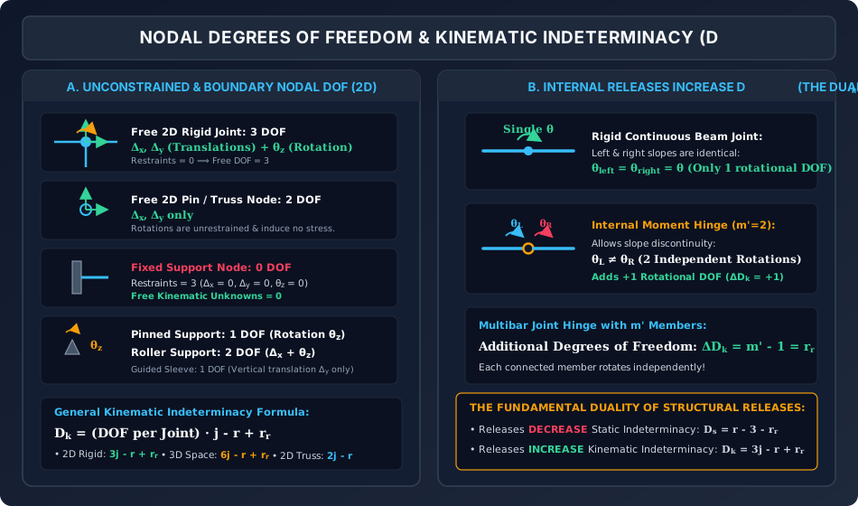
Analytical Walk-Through:
- Nodal DOF Classification (Panel A): Shows the three basic coordinates () at a free rigid joint, two coordinates () at a truss pin, zero at a fixed base, one () at a pinned base, and two () at a roller base.
- Internal Release Kinematics (Panel B): Depicts how an internal hinge splits a single joint rotation into two independent slopes ( and ), demonstrating why releases increase by .
Diagram 2: Axially Deformable vs. Axially Rigid Multi-Story Frames
The graphic below contrasts the 13 degrees of freedom in an axially extensible two-story frame with the 7 degrees of freedom in the same frame when axial deformations are neglected.
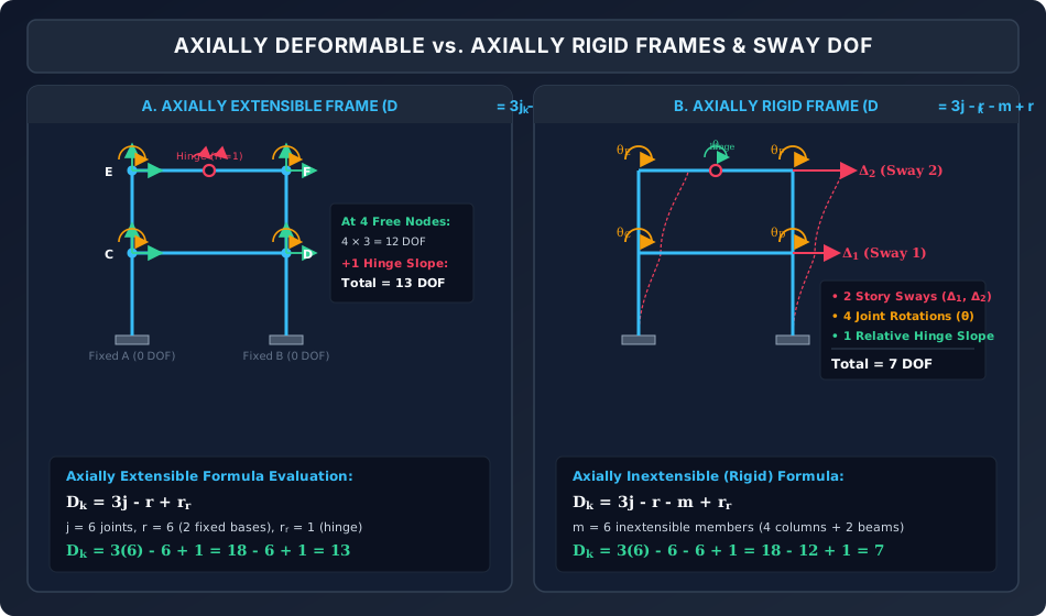
Analytical Walk-Through:
- Axially Extensible Frame (Panel A): Every free joint has independent , , and , yielding .
- Axially Rigid Frame (Panel B): With 6 inextensible members, column shortening is eliminated (), beam elongation is eliminated (coupling lateral sway into story sways and ), reducing the system to ().
4. Comprehensive Comparison Tables
Table 1: Master Kinematic Indeterminacy Formula Matrix
| Structural Skeleton | Axially Extensible (Deformable) | Axially Inextensible (Rigid) | Primary Displacement Unknowns |
|---|---|---|---|
| Beams (2D) | Joint slopes () & deflections () | ||
| Pin-Jointed Truss (2D) | — (Truss bars must deform axially) | Joint translations () | |
| Pin-Jointed Truss (3D) | — (Truss bars must deform axially) | Joint translations () | |
| Rigid Frame (2D) | Joint rotations () & story sways () | ||
| Rigid Frame (3D) | 3 translations & 3 rotations per joint | ||
| Grids (Plane Grid in ) | Vertical deflection & rotations |
Table 2: Nodal DOFs and Boundary Restraints for Standard 2D Supports
| Support / Boundary Type | Reaction Components () | Kinematic Restraints | Free Degrees of Freedom (Unconstrained) |
|---|---|---|---|
| Fully Fixed Support | () | ||
| Pinned / Hinged Support | () | (Joint rotation ) | |
| Horizontal Roller Support | () | (Translation & rotation ) | |
| Vertical Roller Support | () | (Translation & rotation ) | |
| Guided Roller / Sleeve (Horizontal) | () | (Translation only) | |
| Free Joint (Unconnected) | None | () |
Table 3: Static Indeterminacy () vs. Kinematic Indeterminacy ()
| Property | Static Indeterminacy () | Kinematic Indeterminacy () |
|---|---|---|
| Governing Physical Quantity | Unknown redundant forces/moments | Unknown unconstrained displacements/rotations |
| Primary Method of Solution | Force Method (Flexibility Matrix) | Displacement Method (Stiffness Matrix) |
| Effect of Adding Fixed Supports | Increases (adds redundant reactions) | Decreases (constrains joint motions) |
| Effect of Adding Internal Hinges | Decreases () | Increases () |
| Effect of Axially Rigid Assumption | No effect on | Decreases by number of rigid bars () |
| Preferred When | (Fewer equations in force method) | (Fewer equations in stiffness method) |
5. Fully Solved Numerical Examples
Example 1: Multi-Span Continuous Beam with Multiple Supports & Internal Hinge
Problem Statement:
A continuous beam spans over spans () with total length .
- Support : Fixed support ().
- Support : Roller support ().
- Support : Pinned support ().
- Support : Roller support ().
- Span contains an internal moment hinge ().
Calculate:
- Total joints , reactions , and internal releases .
- Kinematic indeterminacy considering axial deformations (extensible).
- Kinematic indeterminacy neglecting axial deformations (axially rigid beams).
- Physical list of all active degrees of freedom.
Step 1: Joint and Boundary Inventory
- Number of joints:
- Total support reaction restraints:
- Internal releases:
- Number of beam members:
Step 2: Case A — Axially Extensible ()
Physical Inventory of the 6 DOF:
- Roller : ()
- Pinned : ()
- Roller : ()
- Hinge at : independent relative rotation ()
Step 3: Case B — Axially Inextensible ()
- Standard Formula vs. Redundant Horizontal Restraint Trap:
In this collinear continuous beam, both Fixed Support () and Pinned Support () provide horizontal reaction restraints ( horizontal support restraints total).
When all spans () are assumed axially rigid (inextensible), . Because there are only horizontal translations to eliminate after , the horizontal pin restraint at is statically redundant along the beam axis (it does not eliminate an additional independent kinematic DOF once axial inextensibility of the 3 members is imposed!).
- 1. Naive Formula Application (treating all and constraints as kinematically independent):
- 2. Exact Physical Kinematic Count ( independent support restraints + axial constraints, or subtracting only the extensible horizontal translations from Case A):
Physical Inventory of the Active Rotational/Hinge DOFs (Axially Inextensible):
With and :
- Slope at Roller : ()
- Slope at Pinned : ()
- Slope at Roller : ()
- Relative rotation at the moment release (): ()
(Note: If the internal hinge is located at mid-span of rather than at a support node and is modeled as a 5th node with , then vertical translation at the mid-span hinge is also free, giving : ).
Example 2: 2D Pin-Jointed Bridge Truss
Problem Statement:
A triangular pin-jointed truss has joints and members.
- Left support is a pinned hinge ().
- Right support is a horizontal roller support ().
All other joints are free.
Calculate the degree of kinematic indeterminacy .
Step 1: Equilibrium & Kinematic Parameters
- Total joints:
- Degrees of freedom per joint: ()
- Total possible nodal translations:
- Boundary restraints:
Step 2: Compute
Physical Identification of 9 DOF:
- At Support (pinned):
- At Support (roller): ( along roller)
- At Joints (4 free joints): ( for each)
Example 3: Two-Story Single-Bay Portal Frame
Problem Statement:
A two-story, single-bay rigid portal frame is shown in Diagram 2.
- The two base supports and are fully fixed ().
- Joints and are rigid at Floor 1 level.
- Joints and are rigid at Roof level.
- Roof beam contains an internal moment hinge at midspan ().
- The frame comprises columns and beams ( members, joints).
Calculate:
- assuming members are axially extensible.
- assuming all members are axially rigid (inextensible).
- Identify every physical degree of freedom for the axially rigid case.
Step 1: Case A — Axially Extensible Frame
Given:
- joints
- reaction restraints
- internal hinge release
Breakdown:
- Bases and : Fully fixed
- Joints :
- Roof hinge: independent relative rotation
Step 2: Case B — Axially Rigid (Inextensible) Frame
All members (4 columns, 2 beams) are inextensible ():
Step 3: Physical Verification of the 7 DOF
- Vertical Displacements ():
Columns and are axially rigid with fixed bases .
Columns and are axially rigid .
(No vertical displacement can occur at any joint). - Horizontal Displacements (Story Sways):
- Floor 1 beam is inextensible ().
- Roof beam is inextensible ().
- Total translational DOF .
- Joint Rotations:
- Rotation at joint :
- Rotation at joint :
- Rotation at joint :
- Rotation at joint :
- Total joint rotations .
- Internal Release:
- Relative slope at roof beam hinge: ().
Sum of physical degrees of freedom:
Conclusion: The analytical formula matches the physical sway decomposition with absolute mathematical precision!
6. Common Misconceptions & High-Yield Exam Traps
Misconception 1: "Internal hinges decrease both static and kinematic indeterminacy"
- The Trap: Subtracting when computing (writing ).
- Correction: Internal releases increase kinematic indeterminacy: A hinge removes rotational continuity, allowing adjacent member ends to rotate independently, which adds unknown rotation coordinates!
Misconception 2: "Truss joints have 3 degrees of freedom"
- The Trap: Applying to a 2D pin-jointed truss.
- Correction: In a pin-jointed truss, member ends rotate freely on frictionless pins without resisting moment. Rotational coordinates do not enter the stiffness matrix or strain energy. A 2D truss joint has only 2 DOF (), giving:
Misconception 3: "Axially rigid assumption applies to trusses"
- The Trap: Subtracting from a truss: .
- Correction: A truss transmits load exclusively through axial tension and compression! If truss members were axially rigid (), the truss could not deform at all (). The inextensible formula applies only to rigid frames and beams where flexure dominates!
Misconception 4: "Every joint in an inextensible frame sways independently"
- The Trap: Counting 2 horizontal sway unknowns per story in a single-bay frame.
- Correction: Inextensible floor beams tie the left and right column heads together (). Each story level in a multi-bay building contributes only one lateral sway translation degree of freedom.
Misconception 5: "A fixed support has if an internal hinge is placed directly adjacent to it"
- The Trap: Assuming the hinge modifies the support boundary condition.
- Correction: A fixed support rigidly clamps the foundation. If an internal hinge is inserted immediately adjacent to the base, the support node remains fixed (0 DOF), but the member end has an independent rotation starting right at the hinge.
7. Previous Years Questions & Benchmark Solutions
Question 1 (GATE CE)
Problem: The kinematic indeterminacy () of a single-bay, single-story portal frame with both column bases fixed to the ground, considering the members to be axially inextensible, is:
(A)
(B)
(C)
(D)
Solution:
- Parameters:
- Number of joints: (2 base joints and 2 eaves joints ).
- Reaction restraints: 2 fixed bases .
- Number of members: columns beam .
- Internal releases: .
- Axially inextensible formula:
- Physical verification:
- 1 lateral sway translation of beam ().
- 2 joint rotations ().
- Total . Correct Answer: (C) 3.
Question 2 (UPSC ESE)
Problem: A continuous beam has support fixed, intermediate support on a roller, and end support pinned. An internal moment hinge is provided at midspan of . Neglecting axial deformations, what is the degree of kinematic indeterminacy?
(A)
(B)
(C)
(D)
Solution:
- Joints: support joints () .
- Boundary restraints:
- Fixed : ()
- Roller : ()
- Pinned : ()
- Total restraints: .
- Members: spans () .
- Internal releases: (hinge in ).
- Compute :
(The 2 free rotations are and , plus the relative slope at the hinge).
Correct Answer: (B) 3 (including relative hinge slope).
Question 3 (SSC JE / State AE)
Problem: What is the kinematic indeterminacy of a plane pin-jointed truss having joints and supported on one pinned support and two roller supports?
(A)
(B)
(C)
(D)
Solution:
- For a 2D pin-jointed truss:
- Total joints: .
- Total support reaction restraints:
- pinned support: restraints
- roller supports: restraints
- Total .
- Compute :
Correct Answer: (B) 12.
8. Quick Revision Formulas & Key Exam Takeaways
╔═══════════════════════════════════════════════════════════════════════════════╗
║                 KINEMATIC INDETERMINACY FORMULA CHEAT SHEET                   ║
╠═══════════════════════════════════════════════════════════════════════════════╣
║ 1. General Formulas for 2D Rigid Frames & Beams:                              ║
║    • Axially Extensible (Deformable):   Dk = 3j - r + rr                      ║
║    • Axially Inextensible (Rigid):       Dk = 3j - r - m + rr                  ║
║      where:                                                                   ║
║      j = total number of joints (including supports)                          ║
║      r = total external support reaction components                           ║
║      m = number of axially rigid members                                      ║
║      rr = internal release count (rr = m' - 1 for moment hinges)              ║
║                                                                               ║
║ 2. Pin-Jointed Trusses:                                                       ║
║    • 2D Plane Truss:  Dk = 2j - r                                             ║
║    • 3D Space Truss:  Dk = 3j - r                                             ║
║    (Trusses CANNOT be assumed axially rigid!)                                 ║
║                                                                               ║
║ 3. Space (3D) Rigid Frames:                                                   ║
║    • Axially Extensible:   Dk = 6j - r + rr                                   ║
║    • Axially Inextensible: Dk = 6j - r - m + rr                               ║
║                                                                               ║
║ 4. Physical Breakdown for Axially Rigid Building Frames:                      ║
║    Dk = (Number of Stories / Sway DOF) + (Free Joint Rotations) + rr          ║
║    • 1-Bay, 1-Story Frame (Fixed Bases):   Dk = 1 sway + 2 rotations = 3      ║
║    • 1-Bay, 2-Story Frame (Fixed Bases):   Dk = 2 sways + 4 rotations = 6     ║
║    • 2-Bay, 2-Story Frame (Fixed Bases):   Dk = 2 sways + 6 rotations = 8     ║
║                                                                               ║
║ 5. The Release Duality Rule:                                                  ║
║    • Releases DECREASE Static Indeterminacy:    Ds = r - 3 - rr               ║
║    • Releases INCREASE Kinematic Indeterminacy: Dk = 3j - r + rr              ║
╚═══════════════════════════════════════════════════════════════════════════════╝