Topic SA-04-01: Influence Lines for Determinate Beams & Girders
Topic SOM-03-01 to SOM-03-04: Shear Force and Bending Moment Diagrams
Learning Objectives:
Distinguish mathematically and conceptually between the maximum internal force at a specified section and the absolute maximum internal force across the entire span.
Construct maximum positive and negative shear force envelopes and maximum bending moment envelopes for rolling concentrated loads and uniformly distributed loads (UDL).
Formulate and apply the Average Load Criterion to determine the critical wheel load producing the maximum bending moment at any given cross-section.
Derive and apply the Focal Point Theorem (Center of Gravity Theorem) to compute the absolute maximum bending moment under a system of moving axle loads.
Apply moving load envelopes to real-world highway and railway bridge girder design according to Indian Road Congress (IRC:6) and Railway Board standards.
2. Theoretical Foundations & Physical Concepts
2.1 The Nature of Live Loads on Bridge Structures
Unlike buildings where gravity dead loads dominate, bridge superstructures (highway overpasses, railway truss spans, plate girder bridges) are primarily governed by transient, moving live loads. Highway traffic consists of multi-axle commercial vehicles (trucks, tractor-trailers, abnormal permit loads), while railway bridges experience heavy locomotive trains followed by freight wagons.
As a vehicular system traverses a bridge span:
The magnitude and distribution of shear force and bending moment vary continuously at every section.
The maximum internal force experienced by a specific cross-section does not occur simultaneously with the maximum internal force at adjacent cross-sections.
Therefore, an ordinary Shear Force Diagram (SFD) or Bending Moment Diagram (BMD)—which represents internal forces for a fixed, stationary load configuration—is insufficient for structural design.
2.2 Definitions of Key Governing Concepts
Maximum Internal Force at a Specific Section x
The peak shear force (Vmax+(x), Vmax−(x)) or bending moment (Mmax(x)) that develops at cross-section x as the moving load system rolls across the span from one support to the other.
Absolute Maximum Internal Force Across the Span
The single largest value of shear force (Vabs,max) or bending moment (Mabs,max) that can occur at any cross-section throughout the entire length L of the beam for any possible position of the moving load system:
A continuous graphical curve that plots the maximum positive and negative design values (Vmax+(x), Vmax−(x), Mmax(x)) as a function of the spatial coordinate x along the span. The structural engineer designs each cross-section (or determines plate thicknesses and flange cover-plate curtailment cut-offs) to safely envelop this maximum internal force curve.
Consider a simply supported beam AB of span L resting on a pin support at A (x=0) and a roller support at B (x=L).
3.1 Single Concentrated Moving Load (W)
Let a single point load of magnitude W traverse the span from left to right.
          W (Moving ->)
          v
   A o==================o B
  x=0        Span L    x=L
(a) Maximum Positive Shear Force Envelope (Vmax+(x))
Recall from SA-04-01 that the Influence Line Diagram (ILD) for shear force at section x has:
A positive ordinate to the right of x, with peak value +(L−x)/L occurring when the load is placed immediately to the right of section x (x+).
Therefore, the maximum positive shear force at section x is:
Vmax+(x)=W(LL−x)
Boundary Values:
At support A (x=0): Vmax+(0)=+W
At midspan (x=L/2): Vmax+(L/2)=+W/2
At support B (x=L): Vmax+(L)=0
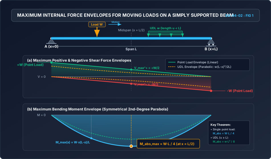
Envelope Profile: A straight line descending linearly from +W at A to 0 at B.
(b) Maximum Negative Shear Force Envelope (Vmax−(x))
The ILD has a negative ordinate to the left of x, with peak value −x/L occurring when the load is placed immediately to the left of section x (x−).
The maximum negative shear force at section x is:
Vmax−(x)=−W(Lx)
Boundary Values:
At support A (x=0): Vmax−(0)=0
At midspan (x=L/2): Vmax−(L/2)=−W/2
At support B (x=L): Vmax−(L)=−W
Envelope Profile: A straight line descending linearly from 0 at A to −W at B.
Absolute Maximum Shear Force:Vabs,max=±W(Occurs at the supports A and B)
(c) Maximum Bending Moment Envelope (Mmax(x))
For any cross-section x, the ILD for bending moment is triangular, with a maximum ordinate at section x:
ηmax(x)=Lx(L−x)
Maximum moment occurs when the concentrated load W sits directly over section x:
Mmax(x)=W⋅ηmax(x)=LWx(L−x)
Equation of the Envelope:
Notice that Mmax(x)=LW(Lx−x2). This is the equation of a symmetrical second-degree parabola with vertex at midspan:
dxdMmax=LW(L−2x)=0⟹x=2L
Absolute Maximum Bending Moment:Mabs,max=Mmax(2L)=LW(L/2)(L/2)=4WL
3.2 Uniformly Distributed Load (UDL) Longer Than the Span (w, Length u≥L)
Let a continuous UDL of intensity w (kN/m) and length u≥L cross the bridge.
(a) Maximum Positive Shear Force Envelope (Vmax+(x))
To maximize positive shear, the UDL must cover the entire positive segment of the shear ILD (from section x to support B, length L−x):
Vmax+(x)=w×[Area of positive triangle]=w×[21(L−x)(LL−x)]=2Lw(L−x)2
Profile: A parabolic curve of second degree, concave upwards.
At x=0: Vmax+(0)=2wL
At x=L/2: Vmax+(L/2)=8wL
At x=L: Vmax+(L)=0
(b) Maximum Negative Shear Force Envelope (Vmax−(x))
To maximize negative shear, the UDL must cover the negative segment of the shear ILD (from support A to section x, length x):
Vmax−(x)=−w×[Area of negative triangle]=−w×[21x(Lx)]=−2Lwx2
Profile: A parabolic curve of second degree.
At x=0: Vmax−(0)=0
At x=L/2: Vmax−(L/2)=−8wL
At x=L: Vmax−(L)=−2wL
Absolute Maximum Shear Force:Vabs,max=±2wL(At the supports)
(c) Maximum Bending Moment Envelope (Mmax(x))
Since the bending moment ILD is entirely positive across the span, the bending moment at any section x is maximized when the entire span is loaded (0 to L):
Mmax(x)=w×[Total area of ILD]=w×[21L(Lx(L−x))]=2wx(L−x)
This is identical to the standard static BMD of a simply supported beam under full UDL!
Absolute Maximum Bending Moment:Mabs,max=8wL2at midspan x=2L
3.3 Uniformly Distributed Load (UDL) Shorter Than the Span (w, Length u<L)
Let a UDL of intensity w and total length u (u<L) roll across the beam. Total load W=w⋅u.
(a) Maximum Shear Force at Section x
Maximum Positive Shear (Vmax+(x)):
Case 1: If (L−x)≥u, the head of the UDL is placed exactly at section x, extending to the right by distance u.
The area under the ILD is a trapezoid with height LL−x at x and LL−x−u at x+u:
Vmax+(x)=w×2u[LL−x+LL−x−u]=Lwu(L−x−2u)
Case 2: If (L−x)<u, the load extends all the way to support B. The effective loaded length is (L−x):
Vmax+(x)=2Lw(L−x)2
Maximum Negative Shear (Vmax−(x)):
Case 1: If x≥u, the tail of the UDL is placed at section x, extending to the left by distance u:
Vmax−(x)=−Lwu(x−2u)
Case 2: If x<u, the load extends all the way to support A:
Vmax−(x)=−2Lwx2
(b) Maximum Bending Moment at Section x (The Average Load Criterion)
Let the UDL of length u straddle section x, with length x1 lying to the left of x and length x2=u−x1 to the right:
           <--- x1 ---> <--- x2 --->
          |===========|=============|   UDL w (length u)
   A -----+-----------+-------------+----- B
   0                  x                   L
The bending moment at section x is:
M(x)=w∫[ILD ordinates under load]
To maximize M(x) with respect to position, let the load shift by an infinitesimal distance dξ to the right:
[!IMPORTANT]
Governing Criterion for Maximum Bending Moment under a Short UDL:
The section x must divide the load length u in the exact same proportion as it divides the span L:
xx1=L−xx2⟺x1=u(Lx),x2=u(LL−x)
Physical Interpretation (Average Load Equality):
Length of Left Segment ACLoad on Left Segment AC=Length of Right Segment CBLoad on Right Segment CB=Total Span LengthTotal Load on Span
Quantitative Formula for Mmax(x)
The area under the ILD over the loaded length u is a trapezoid of width u, parallel sides ηtail and ηmax:
Multiplying by intensity w (where total load W=wu):
Mmax(x)=Lwux(L−x)(1−2Lu)=LWx(L−x)(1−2Lu)
Absolute Maximum Bending Moment (Mabs,max)
Since x(L−x) is maximized at midspan (x=L/2):
Mabs,max=4WL(1−2Lu)=4wuL−8wu2
3.4 System of Concentrated Moving Loads (Train of Axle Loads)
When a train of wheel loads W1,W2,W3,…,Wn traverses a beam, we must solve two distinct problems:
Maximum bending moment at a specified section C (x).
Absolute maximum bending moment across the entire span.
       W1       W2           W3       W4
       |        |            |        |      -> Moving
       v        v            v        v
  A ---+--------+------------+--------+-------- B
  0                                             L
3.4.1 Maximum Bending Moment at a Specified Section x: The Rate of Change Criterion
Let the total resultant of all loads currently on the span be R=∑Wi.
Let the sum of loads currently to the left of section x be Wleft.
As the train rolls a small distance Δξ to the right:
All loads to the left climb up the positive slope +(L−x)/L of the ILD.
All loads to the right descend along the negative slope −x/L of the ILD.
The net change in bending moment at section x is:
ΔM=i∈left∑Wi(+LL−x)Δξ−j∈right∑Wj(Lx)Δξ
Since ∑leftWi=Wleft and ∑rightWj=R−Wleft:
ΔξΔM=Wleft(LL−x)−(R−Wleft)(Lx)=Wleft−R(Lx)
For the bending moment to increase (ΔM>0):
xWleft>LR
For the bending moment to decrease (ΔM<0):
xWleft<LR
[!IMPORTANT]
The Critical Wheel Condition:
The maximum bending moment at a section occurs when a wheel load Wk sits directly over the section such that, as Wk crosses from the right to the left of the section, the average load on the left transitions from less than the average load on the total span to greater:
xWleft−Wk<LR≤xWleft
The wheel load Wk that satisfies this condition is called the critical wheel.
3.5 Absolute Maximum Bending Moment Across the Entire Span: The Focal Point Theorem
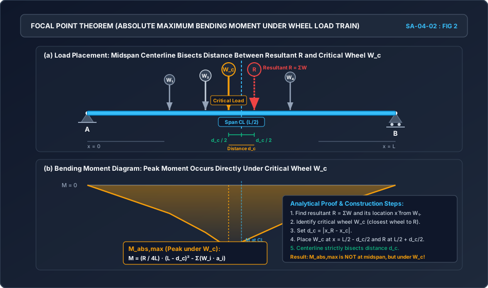
The absolute maximum bending moment in a simply supported beam does not generally occur at midspan! Instead, it occurs directly beneath one of the wheel loads (usually the one closest to the resultant R).
Rigorous Calculus Derivation of the Focal Point Theorem
                     Span Centerline (L/2)
                               |
              <- dc/2 ->       |       <- dc/2 ->
                 Wc            |            R
                  |            |            |
                  v            |            v
    A o-----------+------------+------------+-----------o B
   x=0            |                         |          x=L
             x_c = L/2 - dc/2          x_R = L/2 + dc/2
Definitions:
Let the resultant of the wheel train be R=∑Wi, situated at distance xR from the left support A.
Let Wc be a chosen candidate critical wheel, situated at fixed distance dc from the resultant R.
Without loss of generality, assume Wc is to the left of R, so the position of Wc from A is:
xc=xR−dc
Support Reactions:
By taking moments about support B:
RA⋅L=R(L−xR)⟹RA=LR(L−xR)
Bending Moment Under Wheel Wc:
The moment at the section where Wc is situated is:
Mc=RA⋅xc−i<c∑Wi(xc−xi)
Notice that the term ∑i<cWi(xc−xi) represents the sum of moments of all loads to the left of Wc about Wc. Because axle spacings are rigid, this term is a pure constant (CL):
Mc=LR(L−xR)(xR−dc)−CL
Maximization via First Derivative:
To find the longitudinal position xR that maximizes Mc, differentiate with respect to xR:
[!IMPORTANT]
Statutory Enunciation of the Focal Point Theorem:
The absolute maximum bending moment in a simply supported beam traversed by a train of wheel loads occurs directly under a critical wheel load Wc when the centerline of the span bisects the distance between the critical wheel Wc and the resultant R of the entire load system:
Distance from Midspan to Wc=Distance from Midspan to R=2dc
where ai is the distance from load Wi to the critical wheel Wc.
4. Critical Conditions & Governing Theorems
4.1 Step-by-Step Procedure to Find Absolute Maximum Bending Moment
Compute Total Resultant:R=∑i=1nWi.
Find Position of Resultant: Take moments of all loads about the leading axle W1:
xˉ=R∑Widi
Identify Candidate Critical Wheels: Identify which wheel loads are closest to the resultant R. Typically, test the wheel immediately to the left of R and the wheel immediately to the right of R. (Heavier wheels closer to R dominate).
Apply Bisection Positioning: For each candidate wheel:
Compute distance dc=∣xˉ−dwheel∣.
Position the wheel at x=L/2−dc/2 and the resultant at x=L/2+dc/2.
Check Span Boundaries: Verify that all axles originally assumed to be on the span remain on the span (0≤xi≤L). If any axle rolls off, recompute R and xˉ for the reduced load group.
Calculate Moment: Evaluate Mc=4LR(L−dc)2−∑Wiai. The largest calculated moment is Mabs,max.
4.2 Maximum Shear Force Under a Wheel Train
To produce the maximum positive shear force at any section x:
Place one of the wheel loads directly at the section (x+), with as many other wheels as possible to the right of the section.
A wheel Wk yields the peak shear if advancing the train so the next wheel Wk+1 reaches the section causes the shear to drop:
LR<dkWk
where dk is the spacing between wheel Wk and Wk+1.
For absolute maximum shear across the span, the leading or second axle is placed directly over support A (x=0).
5. Cross-Sectional & Engineering Schematics
5.1 Maximum Shear Force and Bending Moment Envelopes
The following diagram illustrates the continuous envelopes for a single concentrated load and a uniformly distributed load (UDL) traversing a simply supported beam:
Figure 1: Maximum shear force and bending moment envelopes for rolling loads on a simply supported span. Note the linear shear envelope for a point load vs the parabolic shear envelope for a UDL, and the symmetrical parabolic bending moment envelope peaking at midspan.
5.2 The Focal Point Theorem for Axle Trains
The following schematic visualizes the bisection geometry of the Focal Point Theorem and the resulting segmented bending moment diagram:
Figure 2: The Focal Point Theorem geometry. The centerline of the span (CL) strictly bisects the distance dc between the critical wheel Wc and the resultant R. The absolute maximum moment occurs directly under Wc.
6. Solved Numerical Examples
Example 1: Envelopes for Single Concentrated Load and Short UDL
Problem Statement:
A simply supported girder has a clear span of L=20.0 m.
Determine:
The maximum positive shear force, maximum negative shear force, and maximum bending moment at a section C located x=6.0 m from the left support A, caused by a rolling point load P=120.0 kN.
The absolute maximum bending moment across the entire span caused by P.
The maximum positive shear force, maximum negative shear force, and maximum bending moment at the same section C (x=6.0 m) caused by a rolling UDL of intensity w=40.0 kN/m and length u=6.0 m.
The absolute maximum bending moment in the girder caused by this UDL.
Solution:
Step 1: Analysis for Concentrated Load P=120.0 kN
Given L=20.0 m, x=6.0 m, so a=6.0 m, b=L−x=14.0 m.
Maximum Positive Shear at C (VC,max+):
Occurs when P is placed immediately to the right of C (x+):
Conclusion:Wheel 2 is the governing critical wheel!
Step 3: Compute Bending Moment with Wheel 2 at Section C (x=8.0 m)
Wheel positions from left support A:
x1=6.0 m (W1=60 kN)
x2=8.0 m (W2=120 kN, at section C)
x3=8.0+3.0=11.0 m (W3=120 kN)
x4=11.0+2.0=13.0 m (W4=80 kN)
Position of resultant R:
Take moments of loads about A:
R⋅xR=60(6.0)+120(8.0)+120(11.0)+80(13.0)380⋅xR=360+960+1320+1040=3680 kNm⟹xR=3803680=19184≈9.6842 m
Left reaction RA:
RA=LR(L−xR)=24.0380.0×(24.0−9.6842)=24.0380.0×14.3158=226.667 kN
Bending moment at section C (x=8.0 m):
MC=RA×8.0−W1×(8.0−6.0)=226.667×8.0−60.0×2.0MC=1813.333−120.0=1693.333 kNm(169331 kNm=35080 kNm)
Example 3: Absolute Maximum Bending Moment using Focal Point Theorem
Problem Statement:
For the same wheel load train as Example 2 (W1=60 kN,W2=120 kN,W3=120 kN,W4=80 kN; spacings 2.0 m,3.0 m,2.0 m; span L=24.0 m):
Determine:
The position of all loads to produce the absolute maximum bending moment anywhere in the girder.
The exact numerical magnitude of this absolute maximum bending moment (Mabs,max).
Solution:
Step 1: Centroid of the Load System
Taking moments about the lead wheel W1:
xˉ=R∑Widi=380.060(0)+120(2.0)+120(5.0)+80(7.0)=380.00+240+600+560=380.01400.0=1970≈3.6842 m
The resultant R=380 kN acts at 3.6842 m behind wheel 1.
Step 2: Identification of Candidate Critical Wheels
Distances from resultant R to adjacent wheels:
Distance to Wheel 2 (at 2.0 m from W1):
dc2=3.6842−2.0=1.6842 m(1932 m)
Distance to Wheel 3 (at 5.0 m from W1):
dc3=5.0−3.6842=1.3158 m(1925 m)
Because dc3<dc2 (1.3158 m<1.6842 m) and both wheels have identical magnitude (120 kN), Wheel 3 is closest to the resultant and is the prime candidate. We will test both to provide an irrefutable proof.
Step 3: Application of Focal Point Theorem for Wheel 3 (W3)
Wheel 3 lies to the right of resultant R by dc3=1925 m≈1.3158 m.
By the Focal Point Theorem, the midspan of the beam (L/2=12.0 m) must bisect the distance between R and W3:
Position of Resultant R:
xR=2L−2dc3=12.0−3825=38431≈11.3421 m from A
Position of Critical Wheel W3:
x3=2L+2dc3=12.0+3825=38481≈12.6579 m from A
Check positions of all wheels on span:
x1=x3−5.0=12.6579−5.0=7.6579 m>0 (On span)
x2=x3−3.0=12.6579−3.0=9.6579 m (On span)
x4=x3+2.0=12.6579+2.0=14.6579 m<24.0 m (On span)
All four wheels are completely on the span!
Step 4: Verification under Candidate Wheel 2 (W2)
For completeness, test Wheel 2 (dc2=1932 m≈1.6842 m, to the left of R):
Midspan (12.0 m) bisects W2 and R:
x2=12.0−3832=38424≈11.1579 mxR=12.0+3832=38488≈12.8421 m
Left reaction:
RA=24.0380.0×(24.0−12.8421)=176.6667 kN
Moment under Wheel 2:
Mmax(W2)=RA⋅x2−W1×2.0=176.6667×11.1579−120.0=1971.2281−120.0=1851.228 kNm
Step 5: Final Comparison & Conclusion
Mmax(W3)=1876.853 kNm>Mmax(W2)=1851.228 kNm
Therefore:
Mabs,max=1876.853 kNm
It occurs directly under Wheel 3 when Wheel 3 is positioned at 12.658 m from the left support A (with the resultant at 11.342 m).
7. Engineering Design Applications & Field Practice
7.1 Bridge Girder Flange Cover Plate Cut-offs
In steel plate girder bridges (governed by IRC:24 and IS:800), the required section modulus Zreq(x)=Mmax(x)/σallow varies along the span according to the parabolic bending moment envelope.
Instead of using a constant heavy flange plate throughout the entire span, fabricators curtail the flange plates:
Base flange plate runs the full span.
First cover plate is added over the middle 60–70% of the span.
Second cover plate is added over the middle 30–40% of the span.
The theoretical cut-off points are obtained by intersecting the moment resistance capacities of the curtailed sections with the Moving Load Moment Envelope.
The maximum shear force envelope (Vmax+(x) and Vmax−(x)) governs the design of plate girder webs:
Near the supports (x→0,x→L), shear force reaches its absolute peak (Vabs,max). Web plates require thick web thickness and closely spaced vertical stiffeners (spacing d≈0.5dw to 0.8dw).
Near midspan (x≈L/2), shear force drops to its minimum (Vmax≈W/2 or wL/8). Stiffener spacing can be increased to maximum allowable spacing (d≈1.5dw).
7.3 Standard Design Vehicle Load Models
Authority / Standard
Vehicle Class / Designation
Axle Configuration & Magnitude
Application
IRC:6 (Highway)
Class 70R (Tracked)
700 kN total weight over two tracks (4.57 m length)
2 locomotives (4×245.25 kN per loco) + trailing train of 80.93 kN/m
Mainline heavy freight and passenger corridors
AASHTO (USA)
HL-93
Design truck (35.6+142.3+142.3 kN) + design lane load (9.34 kN/m)
US interstate and state highway bridges
8. Comparative Analysis & Summary Matrix
8.1 Summary of Governing Formulas for Simply Supported Span L
Load Type
Maximum Positive Shear at x (Vmax+)
Maximum Negative Shear at x (Vmax−)
Maximum Bending Moment at x (Mmax)
Absolute Maximum Moment (Mabs,max)
Location of Mabs,max
Single Concentrated Load (W)
+W(LL−x)
−W(Lx)
LWx(L−x)
4WL
Exactly at Midspan (x=L/2)
Full UDL (w, u≥L)
+2Lw(L−x)2
−2Lwx2
2wx(L−x)
8wL2
Exactly at Midspan (x=L/2)
Short UDL (w, u<L, W=wu)
+Lwu(L−x−2u)
−Lwu(x−2u)
LWx(L−x)(1−2Lu)
4WL(1−2Lu)
Exactly at Midspan (x=L/2)
Two Concentrated Loads (W1,W2, spacing d)
Leading or trailing wheel at section
Leading or trailing wheel at section
Critical wheel at section (average load criterion)
4LR(L−dc)2 under heavier wheel
Distance dc/2 from Midspan
Train of Axle Loads (W1…Wn)
Wheel at section satisfying LR<dkWk
Wheel at section satisfying negative criterion
Wheel at section where xWleft−Wk<LR≤xWleft
4LR(L−dc)2−∑Wiai under critical wheel Wc
Under Wc placed at x=2L−2dc
9. Common Misconceptions & Exam Pitfalls
[!CAUTION]
Trap 1: Assuming Absolute Maximum Moment for a Wheel Train Always Occurs at Midspan
Students routinely place the resultant R or the critical wheel Wc at midspan (x=L/2). Reality: Midspan must bisect the distance between R and Wc. Thus, both R and Wc are shifted away from midspan by dc/2. The peak moment occurs directly under Wc at x=L/2−dc/2, never at midspan (unless dc=0, i.e., Wc coincides with R).
[!WARNING]
Trap 2: Forgetting to Check if Wheels Roll Off the Span
When applying the Focal Point Theorem, positioning the critical wheel at L/2−dc/2 shifts the entire train. If a lead or trail wheel drops off the bridge (xi<0 or xi>L), the resultant R and its position xˉ change! Remedy: Always verify 0≤xi≤L for every wheel. If a wheel leaves the span, recompute R without that wheel.
[!WARNING]
Trap 3: Confusing the Shear Step with Negative Shear
For a rolling point load, the maximum positive shear at x is +W(L−x)/L (load at x+) and the maximum negative shear is −Wx/L (load at x−). The algebraic difference between them is +W(L−x)/L−(−Wx/L)=W, which is the magnitude of the load! Do not confuse this with zero shear.
[!NOTE]
Trap 4: Average Load Criterion for Short UDL
When maximizing bending moment at section x for a short UDL (u<L), students often place the center of the load at x. Reality: The center of the load is placed at xonly if x=L/2 (midspan). For any other section, the section must divide the load in the ratio x/(L−x), which means x1=u(x/L)=u/2.
A simply supported beam of span 10 m is subjected to a moving point load of 100 kN. The absolute maximum bending moment in the beam is:
(A) 200 kNm
(B) 250 kNm
(C) 500 kNm
(D) 1000 kNmSolution:Mabs,max=4WL=4100×10=250 kNm. Correct option is (B).
Question 2 (UPSC ESE / IES)
Two concentrated loads of 40 kN and 60 kN spaced 2 m apart move across a simply supported girder of span 10 m from left to right, with the 40 kN load leading. The absolute maximum bending moment occurs:
(A) At midspan under the 40 kN load
(B) At midspan under the 60 kN load
(C) Under the 60 kN load at a distance of 4.6 m from the left support
(D) Under the 60 kN load at a distance of 4.6 m from the right support
Solution:
Total load R=40+60=100 kN.
Centroid from 60 kN load: dc=10040×2.0=0.8 m towards the 40 kN load.
Absolute maximum moment occurs under the heavier 60 kN load.
Midspan (5.0 m) bisects the distance between 60 kN load and R (dc=0.8 m).
Distance of 60 kN load from nearest support: 5.0−20.8=4.6 m. Correct option is (C) (or (D) by symmetry).
Question 3 (SSC JE / State AE)
When a uniformly distributed load shorter than the span moves over a simply supported beam, the bending moment at any section is maximum when:
(A) The head of the load is at the section
(B) The tail of the load is at the section
(C) The section divides the load in the same ratio as it divides the span
(D) The center of the load is at the section
Solution: Option (C).
11. Practice Problems with Answer Keys
Problem 1 (Point Load Envelope)
A simply supported crane runway girder has an effective span of 12.0 m. A wheel load of 80.0 kN rolls across the girder.
(a) Compute the maximum positive shear force at x=3.0 m from the left support.
(b) Compute the maximum negative shear force at x=3.0 m.
(c) Compute the maximum bending moment at x=3.0 m.
(d) Compute the absolute maximum bending moment in the girder.
Answer Key:
(a) Vmax+=80×(9/12)=+60.0 kN
(b) Vmax−=−80×(3/12)=−20.0 kN
(c) Mmax(3m)=80×(3×9)/12=180.0 kNm
(d) Mabs,max=80×12/4=240.0 kNm (at x=6.0 m)
Problem 2 (Short UDL on Bridge Girder)
A highway girder of span 16.0 m is traversed by a rolling UDL of 30.0 kN/m having a length of 5.0 m.
Determine:
(a) The maximum positive shear force at x=4.0 m.
(b) The maximum bending moment at x=4.0 m.
(c) The absolute maximum bending moment across the span.
Answer Key:
(a) L−x=12.0 m≥u=5.0 m.
Vmax+=1630×5(12.0−2.5)=16150×9.5=+89.06 kN
(b) x1=5×(4/16)=1.25 m, x2=3.75 m.
Mmax(4m)=16150×4×12(1−325)=450×(3227)=379.69 kNm
Two wheel loads of 100.0 kN and 50.0 kN spaced 3.0 m apart cross a span of 15.0 m with the 100.0 kN load leading.
Calculate the absolute maximum bending moment developed in the span.
Answer Key:
R=150.0 kN.
Centroid from 100 kN load: dc=15050×3.0=1.0 m towards the 50 kN load.
Distance between 100 kN load and R is dc=1.0 m.
Position 100 kN load at x=15/2−1.0/2=7.0 m from left support; R is at 8.0 m.
RA=15150×(15−8)=70.0 kN.
Mabs,max=70.0×7.0=490.0 kNm (occurring under the 100 kN load at x=7.0 m).
12. Comprehensive Subject & Examination Mapping
Competitive Examination
Relevant Section / Paper
Expected Weightage
Typical Question Style
GATE CE
Structural Analysis / Structural Engineering
2–4 Marks
Numerical Answer Type (NAT) on absolute maximum bending moment, position of critical load under wheel train, or short UDL moment.
UPSC ESE
Paper-I (Structural Analysis)
8–16 Marks
Objective multiple choice on Focal Point Theorem geometry, and conventional numerical derivation of maximum bending moment envelope.
SSC JE
Structural Engineering (Theory of Structures)
2–4 Marks
Direct formula recognition (WL/4, wL2/8, average load criterion, linear vs parabolic envelopes).
State AE / JE
Civil Engineering Paper-I
3–6 Marks
Bisection of distance between resultant and wheel load, maximum shear at supports, and critical wheel identification.
RRB JE
Civil & Allied Engineering (Structural Mechanics)
2–3 Marks
Conceptual questions on moving loads, impact factor, and maximum moment at midspan.