Three-Hinged Arches & Eddy's Theorem
In this chapter (4 topics)
On this page
- 1. Module Header & Metadata Block
- 2. Theoretical Foundations & Physical Concepts
- 2.1 The Evolution of Arch Action
- 2.2 Static Determinacy & Geometric Stability of the Three-Hinged Arch
- 3. Mathematical Derivations & Analytical Formulations
- 3.1 Geometry of Standard Arch Ribs
- 3.2 Internal Force Resultants at Any Cross-Section D (x, y)
- 3.3 Eddy's Theorem (1878)
- 3.4 Temperature Effects and Support Settlements
- 4. Critical Conditions & Governing Theorems
- 4.1 Summary of Governing Formulas for Symmetrical Three-Hinged Arches
- 5. Cross-Sectional & Engineering Schematics
- 5.1 Three-Hinged Arch Mechanics, Resultants & Eddy's Theorem
- 5.2 Arch with Springings at Different Levels & Thermal Response
- 6. Solved Numerical Examples
- Example 1: Analysis of a Parabolic Arch under Combined Loading
- Example 2: Circular Arch vs Parabolic Arch & Eddy's Theorem Verification
- Example 3: Parabolic Arch with Springings at Different Levels
- 7. Engineering Design Applications & Field Practice
- 7.1 Masonry Arches and the Middle-Third Rule
- 7.2 Abutment Design & Tie-Rods
- 8. Comparative Analysis & Summary Matrix
- 8.1 Comparison of Three-Hinged vs Two-Hinged vs Fixed Arches
- 9. Common Misconceptions & Exam Pitfalls
- 10. Previous Years' Examination Analysis & Reference Questions
- 10.1 Typical Competitive Examination Questions
- 11. Practice Problems with Answer Keys
- Problem 1 (Parabolic Arch Radial Shear)
- Problem 2 (Thermal Crown Rise)
- Problem 3 (Arch with Unequal Springings)
- 12. Comprehensive Subject & Examination Mapping
1. Module Header & Metadata Block
- Topic ID:
SA-05-01 - Module: Structural Analysis (Subject 03)
- Chapter: Chapter 05: Arches & Suspension Cables
- Title: Three-Hinged Arches & Eddy's Theorem
- Target Examinations:
- GATE Civil Engineering (Structural Engineering)
- UPSC Engineering Services Examination (ESE/IES Paper-I)
- SSC JE Civil Engineering (Theory of Structures)
- State Public Service Commission Assistant Engineer (AE) & Junior Engineer (JE) Examinations
- Railway Recruitment Board Junior Engineer (RRB JE)
- Prerequisites:
- Topic
SA-01-01: Static Indeterminacy of Trusses & Arches - Topic
SOM-03-01toSOM-03-04: Shear Force and Bending Moment Diagrams - Topic
SA-04-03: Influence Lines for Trusses & Three-Hinged Arches
- Topic
- Learning Objectives:
- Understand the fundamental structural mechanics of arch action and differentiate arch compressive thrust from beam flexure.
- Derive the geometric profile equations and tangent slopes for standard three-hinged parabolic and circular (segmental) arches.
- Formulate the equations of equilibrium for three-hinged arches with springings at the same level and at different levels.
- Calculate the internal force resultants: Bending Moment (), Normal Thrust (), and Radial Shear () at any cross-section.
- State, prove, and apply Eddy's Theorem to determine bending moments graphically and analytically from the line of thrust (funicular polygon).
- Prove analytically why temperature changes and support settlements induce zero internal stress in three-hinged arches, and calculate the resulting kinematic crown displacement.
2. Theoretical Foundations & Physical Concepts
2.1 The Evolution of Arch Action
From antiquity (Roman aqueducts and medieval cathedral vaults) to modern long-span bridges, the arch represents one of humanity's most efficient structural forms:
- Beams: Carry transverse loads purely by flexural internal moments () and transverse shear (), creating severe tensile and compressive bending stresses: For long spans, dead load flexure causes massive girder depths and excessive self-weight.
- Arches: Curved structural members spanning across an opening, resting on abutments capable of resisting both vertical downward reactions and horizontal inward thrusts (). The horizontal thrust generates a counter-acting hogging moment () that directly relieves the beam sagging moment: By shaping the arch rib to closely follow the funicular polygon (line of thrust) of the dominant gravity loads, the flexural bending moment is minimized or completely eliminated throughout the span, allowing the structure to carry massive loads primarily in direct axial compression.
2.2 Static Determinacy & Geometric Stability of the Three-Hinged Arch
A three-hinged arch consists of two curved structural segments connected to each other by an internal hinge at the crown (), and connected to rigid abutments by pin supports at the springings ( and ).
                      Crown Hinge C
                           (o)
                          /   \
                         /     \
                        /       \
                       /         \
        Pin A (o)-----+-----------+-----(o) Pin B
              x=0                        x=L
Static Determinacy Evaluation:
- Support reactions: ( at ; at ).
- Global equations of static equilibrium: ().
- Special internal condition equations: (Internal hinge at crown enforces ).
- Degree of static indeterminacy:
Stability Requirement (Non-Collinearity of Hinges):
For geometric stability, the three hinges () must not lie on a single straight line. If the three hinges become collinear (), the arch degenerates into a three-pinned toggle mechanism that undergoes catastrophic rigid-body collapse under vertical loads ().
3. Mathematical Derivations & Analytical Formulations
3.1 Geometry of Standard Arch Ribs
3.1.1 Parabolic Arch with Supports at the Same Level
Let the origin be taken at the left springing .
- Span , Central rise .
- Crown hinge is at , and right support is at .
The equation of a symmetric parabola passing through , , and is:
The slope of the arch axis at any cross-section is:
- At left support ():
- At crown (): (horizontal)
- At right support ():
Trigonometric relations at section :
3.1.2 Circular (Segmental) Arch with Supports at the Same Level
Let an arch rib form a circular segment of radius , span , and central rise .
               Crown C
                 ---
              /   h   \
       A o---+---------+---o B
             |<- L/2 ->|
             |         |
             |  R - h  |
             |         |
                 (O) Center of Curvature
-
Radius of Curvature (): By the intersecting chords theorem for a circle:
-
Equation of Arch Rib: With origin at the left support (): The horizontal distance from the center of curvature (vertical centerline of span) is . By the Pythagorean theorem:
-
Slope of Circular Rib:
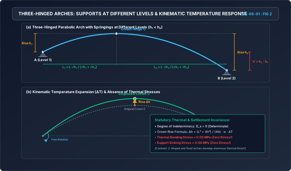
3.1.3 Parabolic Arch with Supports at Different Levels (Springings Differing by )
Let the left support be at vertical depth below the crown , and the right support be at vertical depth below .
- Total horizontal span: , where is the horizontal distance from to crown , and is from to .
- Difference in springing levels: .
                      Crown Hinge C (0,0)
                           (o)
                          /   \
           Rise h1       /     \
             v          /       \
      Pin A (o)--------+         \     Rise h2
                                  \      v
                             ------+---(o) Pin B
               <-- L1 --> <---- L2 ---->
               <---------- L ---------->
With the origin at the crown hinge (, measuring downward):
- Left segment :
- Right segment :
Equating the parabolic constant :
Using the ratio theorem ():
[!IMPORTANT] Horizontal Position of the Crown for Unequal Springings:
Horizontal Thrust under Full Uniform Load ():
Taking moments about crown hinge :
- For segment :
- For segment : Substituting :
3.2 Internal Force Resultants at Any Cross-Section ()
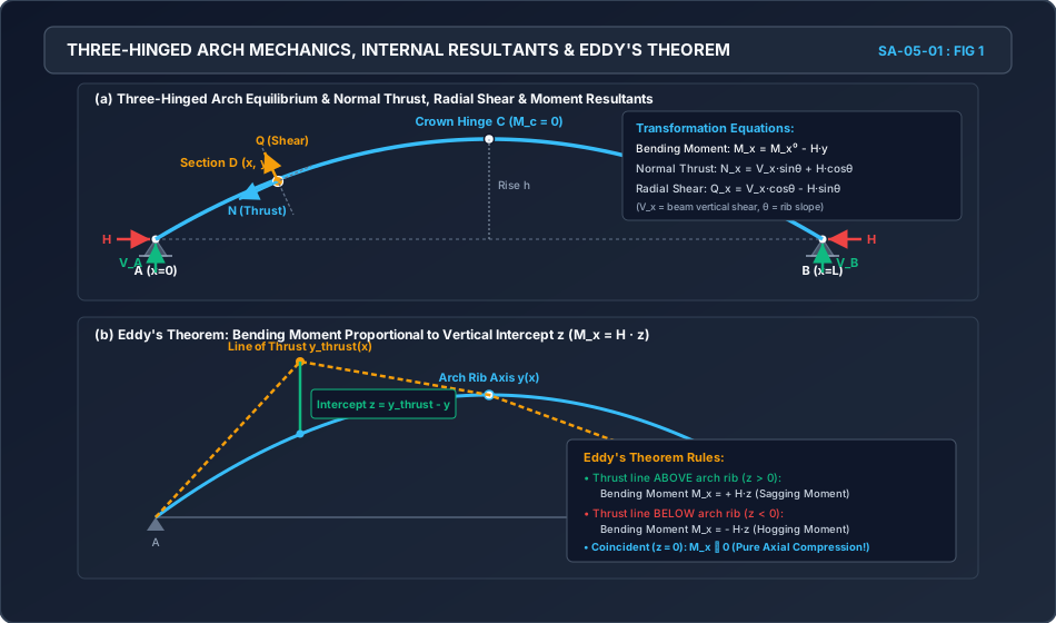
Consider an arch cross-section cut at coordinate with vertical ordinate and inclination to the horizontal.
                  Normal Axis
                      ^
                      |  Q_x (Radial Shear)
                      |  ^
                      | /
            Rib       |/   θ
        --------------+-------------> Tangent Axis
                     /|             N_x (Normal Thrust)
                    / |
                   v  |
                  M_x
-
Bending Moment ():
where is the bending moment in a simply supported beam of span carrying the identical vertical loads.
- Sagging Moment (): Produces tension on the intrados (bottom fiber).
- Hogging Moment (): Produces tension on the extrados (top fiber).
-
Normal Thrust (): The resultant axial compressive force acting perpendicular to the cut cross-section (along the tangent to the rib):
where is the vertical shear force in the corresponding simply supported beam at section .
-
Radial Shear (): The transverse shear force acting parallel to the cut cross-section (along the normal to the rib):
3.3 Eddy's Theorem (1878)
American engineer Henry T. Eddy established an elegant graphical and analytical theorem that directly relates the bending moment at any arch cross-section to the geometry of the Line of Thrust (Funicular Polygon).
Formal Enunciation of Eddy's Theorem:
"The bending moment at any cross-section of an arch rib is directly proportional to the vertical intercept between the center-line of the arch rib and the line of thrust for the given loading system."
Rigorous Analytical Proof:
Let an arch rib have a centerline profile measured vertically above the springing line. Let the line of thrust (the funicular polygon for the given loading system, drawn with a pole distance equal to the horizontal thrust ) have a vertical ordinate measured above the springing line.
       Bending Moment = H · z

         Thrust Line y_thrust(x)
                 \
                  \   +z (Thrust line above arch -> Sagging)
                   \---\
          -------------\------- Arch Rib Axis y(x)
                        \
                         \  -z (Thrust line below arch -> Hogging)
                          \
- By graphic statics and the fundamental property of the funicular polygon, the beam bending moment at any section is equal to the pole distance multiplied by the funicular polygon ordinate:
- The actual bending moment in the arch rib is:
- Substitute :
- Defining the vertical intercept :
Engineering Consequences of Eddy's Theorem:
- Case 1: : The thrust line lies above the arch rib. The bending moment is positive (Sagging), causing tension at the intrados.
- Case 2: : The thrust line lies below the arch rib. The bending moment is negative (Hogging), causing tension at the extrados.
- Case 3: : The thrust line coincides exactly with the arch rib axis. The bending moment is identically zero everywhere ( for all ). The arch rib is in a state of pure axial compression!
[!NOTE] Why Parabolic Arches Carry Uniform Gravity Loads with Zero Moment: The funicular polygon for a uniformly distributed gravity load () is a parabola with central ordinate . If the arch rib is built to a parabolic profile of rise , the line of thrust coincides perfectly with the rib axis (). Hence, and across the entire span!
3.4 Temperature Effects and Support Settlements
In statically indeterminate structures (such as two-hinged or fixed arches), a change in temperature or a settlement of the supports induces massive horizontal thrusts and severe flexural stresses.
In a Three-Hinged Arch ():
- The structure is statically determinate.
- When the ambient temperature changes by , or when abutment settles vertically or spreads horizontally, the two segments and rotate freely as rigid bodies about the hinges , , and .
- No internal strain, bending moment, or thermal stress is developed anywhere in the arch!
Kinematic Crown Rise under Temperature Increase ():
Let be the coefficient of thermal expansion. Each half-segment of the arch (approximate chord length ) expands by:
From the geometry of the triangle :
Differentiating with respect to temperature (keeping span constant because abutments are rigid):
Substitute :
4. Critical Conditions & Governing Theorems
4.1 Summary of Governing Formulas for Symmetrical Three-Hinged Arches
| Parameter | Parabolic Arch Rib | Circular (Segmental) Arch Rib |
|---|---|---|
| Profile Equation | ||
| Radius of Curvature | Variable: | Constant: |
| Slope Equation | ||
| Thrust under Full UDL () | ||
| Bending Moment under Full UDL | (Zero throughout) | (Small hogging moments) |
| Effect of or Sinking | Zero stress; crown rises by | Zero stress; crown rises by |
5. Cross-Sectional & Engineering Schematics
5.1 Three-Hinged Arch Mechanics, Resultants & Eddy's Theorem
The following schematic illustrates the equilibrium of a three-hinged arch, the resolution of internal forces into Normal Thrust () and Radial Shear (), and the geometric proof of Eddy's Theorem:
5.2 Arch with Springings at Different Levels & Thermal Response
The following diagram details the geometry of a three-hinged arch with unequal support levels, along with the kinematic deformation under temperature changes:
6. Solved Numerical Examples
Example 1: Analysis of a Parabolic Arch under Combined Loading
Problem Statement: A three-hinged parabolic arch has a clear span of and a central rise of . The supports and are at the same level. The arch carries:
- A concentrated point load of at from left support (quarter-span).
- A uniformly distributed load of on the right half of the span (from to ).
Determine:
- The vertical reactions and , and the horizontal thrust .
- The bending moment, normal thrust, and radial shear at the quarter-span section () just to the left and just to the right of the concentrated load.
                   P = 120 kN          w = 20 kN/m
                       v           |=================|
                      (D)          |                 |
          Pin A (o)----+-----------+-----------------(o) Pin B
               x=0   x=7.5m      x=15m              x=30m
Solution:
Step 1: Support Reactions
Total UDL load: , acting at from .
-
Vertical Reaction at (): Taking moments about support :
-
Vertical Reaction at ():
-
Horizontal Thrust (): Crown hinge is at . Consider equilibrium of left half segment ():
(Check equilibrium of right segment : . Validated!)
Step 2: Arch Geometry at Section ()
- Vertical rise:
- Slope:
Step 3: Bending Moment at Section ()
Step 4: Normal Thrust and Radial Shear at Section
-
Just to the Left of the Point Load (): Beam vertical shear: .
- Normal Thrust ():
- Radial Shear ():
-
Just to the Right of the Point Load (): Beam vertical shear: .
- Normal Thrust ():
- Radial Shear ():
- Verification of Discontinuities (Jumps):
Example 2: Circular Arch vs Parabolic Arch & Eddy's Theorem Verification
Problem Statement: A three-hinged circular arch has a clear span of and a central rise of . A uniformly distributed gravity load of covers the entire span.
- Determine the radius of curvature and the vertical ordinate of the circular arch at quarter-span ().
- Calculate the horizontal thrust and the bending moment at quarter-span using direct equilibrium.
- Apply Eddy's Theorem to compute the bending moment and verify the result.
- Compare the bending moment with that of a three-hinged parabolic arch of the same span and rise.
Solution:
Step 1: Circular Arch Geometry
- Radius of curvature :
- Depth of springing below center of curvature:
- Vertical ordinate at quarter-span (, distance from crown ):
Step 2: Direct Equilibrium Calculation
- Vertical reaction: .
- Horizontal thrust : Taking moment about crown hinge ():
- Beam bending moment at :
- Actual bending moment in circular arch:
Step 3: Application of Eddy's Theorem
For a uniform gravity load , the funicular polygon (line of thrust) is a parabola passing through the three hinges:
At :
The vertical intercept between the arch rib and the thrust line is:
(The arch rib lies ABOVE the line of thrust!)
By Eddy's Theorem:
Step 4: Comparison with Parabolic Arch
For a parabolic arch of the same span and rise:
Engineering Conclusion: Under a uniform gravity load, a parabolic arch develops zero bending moment, whereas a circular arch develops an internal hogging moment of due to geometric divergence from the funicular curve.
Example 3: Parabolic Arch with Springings at Different Levels
Problem Statement: A three-hinged parabolic arch has a clear horizontal span of . The left springing is located at a depth of below the crown hinge . The right springing is located at a depth of below the crown hinge (level difference ). The arch supports a uniformly distributed gravity load of across its entire horizontal span.
Determine:
- The horizontal position of the crown hinge relative to supports and ( and ).
- The horizontal thrust .
- The vertical support reactions and .
- The bending moment and normal thrust at the crown hinge .
Solution:
Step 1: Location of Crown Hinge
Using the derived level-ratio formulas with :
(Check: . Correct.)
Step 2: Horizontal Thrust ()
(Check from right segment: . Consistent!)
Step 3: Vertical Support Reactions
For left half (segment width ):
For right half (segment width ):
Total vertical reaction:
Step 4: Forces at the Crown Hinge
- Bending Moment (): By definition of the internal hinge, .
- Normal Thrust at Crown (): At the crown vertex, the tangent is horizontal ():
- Radial Shear at Crown ():
7. Engineering Design Applications & Field Practice
7.1 Masonry Arches and the Middle-Third Rule
Because unreinforced masonry (stone and brick) has negligible tensile strength, masonry arches must be detailed so that no tensile stress develops across the joints:
To ensure (no tension):
By Eddy's Theorem, the eccentricity is directly related to the vertical intercept . The line of thrust must remain strictly within the middle third of the arch rib ring () under all load cases to prevent joint opening and hinge formation.
       Extrados
     =====================
         Middle Third (d/3)  <- Line of thrust must stay inside
     ---------------------
       Intrados
7.2 Abutment Design & Tie-Rods
The massive horizontal thrust exerts outward horizontal force on the abutments.
- On firm rock foundations: Heavy gravity abutments transfer directly into the bedrock.
- On weak soils: A horizontal tie-rod connects springings and , absorbing the tension and transforming the foundation load into pure vertical bearing pressure (Tied Arch Bridge).
8. Comparative Analysis & Summary Matrix
8.1 Comparison of Three-Hinged vs Two-Hinged vs Fixed Arches
| Engineering Characteristic | Three-Hinged Arch | Two-Hinged Arch | Fixed Arch (Hingeless) |
|---|---|---|---|
| Static Indeterminacy () | (Determinate) | ||
| Thermal Stresses () | Zero Stress (Hinges rotate freely) | High Stress () | Extremely High Stress |
| Abutment Settlement Sensitivity | Completely Insensitive (Zero stress) | Moderately Sensitive | Severely Sensitive (Cracking risk) |
| Bending Moment Distribution | Higher positive/negative moments under live loads | Lower peak moments ( reduction) | Lowest peak moments across span |
| Construction Complexity | Complex hinge fabrication and maintenance | Standard pin bearings | Monolithic, no hinge maintenance |
9. Common Misconceptions & Exam Pitfalls
[!CAUTION] Trap 1: Assuming That Supports at Different Levels Have Equal Spans to Crown
When springings are at different levels (), students often place the crown at midspan ().
Reality: The crown shifts toward the higher support (). and are proportional to and , respectively!
[!WARNING] Trap 2: Confusing Normal Thrust with Horizontal Thrust
Students frequently write .
Reality: . equals only at the crown where the tangent is horizontal (). At the springings, is substantially larger than because of the vertical shear component .
[!WARNING] Trap 3: Forgetting That Circular Arches Have Bending Moments Under Full UDL
Students often generalize the zero-moment property of parabolic arches to all arches.
Reality: A circular arch rib deviates from a parabola, producing an intercept . By Eddy's Theorem, circular arches develop significant hogging moments under uniform gravity loading!
10. Previous Years' Examination Analysis & Reference Questions
10.1 Typical Competitive Examination Questions
Question 1 (GATE Civil Engineering)
A three-hinged parabolic arch of span and rise carries a uniformly distributed load of per unit run over the entire span. The horizontal thrust at each support is:
- (A)
- (B)
- (C)
- (D) Solution: Option (B).
Question 2 (UPSC ESE / IES)
According to Eddy's theorem, the bending moment at any section of an arch rib is equal to:
- (A) The horizontal thrust multiplied by the vertical intercept between the arch axis and the line of thrust
- (B) The vertical reaction multiplied by the span
- (C) The normal thrust multiplied by the arch thickness
- (D) The product of radial shear and rise Solution: Option (A).
Question 3 (SSC JE / State AE)
A three-hinged arch is:
- (A) Statically determinate and geometrically stable
- (B) Statically indeterminate of degree 1
- (C) Statically indeterminate of degree 3
- (D) Unstable under vertical loads Solution: Option (A).
11. Practice Problems with Answer Keys
Problem 1 (Parabolic Arch Radial Shear)
A three-hinged parabolic arch of span and rise carries a central concentrated load of at the crown. Calculate the radial shear developed at a section from the left support.
Answer Key:
- .
- .
- Slope at : .
- Vertical shear at : .
- Radial shear: . (Remarkable Result: Under a central concentrated load, the funicular polygon consists of two straight chords and . At , the parabolic rib slope matches the chord slope!)
Problem 2 (Thermal Crown Rise)
A three-hinged parabolic arch has a span of and rise of . The coefficient of thermal expansion is . Calculate the vertical rise of the crown when the temperature increases by .
Answer Key:
Problem 3 (Arch with Unequal Springings)
A three-hinged parabolic arch has span . Left support is below the crown, and right support is below the crown. Find the horizontal distance of the crown from the left support.
Answer Key:
12. Comprehensive Subject & Examination Mapping
| Competitive Examination | Relevant Section / Paper | Expected Weightage | Typical Question Style |
|---|---|---|---|
| GATE CE | Structural Engineering (Analysis) | Numerical problems on normal thrust and radial shear, Eddy's theorem applications, or arches with unequal springings. | |
| UPSC ESE | Paper-I (Structural Analysis) | Proof of Eddy's Theorem, derivation of thermal invariance, and complete analysis of parabolic vs circular arches. | |
| SSC JE | Theory of Structures | Formulas for horizontal thrust , statement of Eddy's theorem, and middle-third rule for masonry arches. | |
| State AE / JE | Civil Engineering Paper-I | Calculation of normal thrust at springings and location of crown hinge for unequal springings. | |
| RRB JE | Structural Mechanics | Basic determinacy of three-hinged arch, role of crown hinge, and temperature behavior. |