An arch is a curved structural member designed primarily to carry transverse gravitational loads via axial compression (thrust), drastically reducing bending moments compared to equivalent straight simply supported beams. While a three-hinged arch is statically determinate (Ds=0), the introduction of structural continuity by eliminating the crown hinge yields the two-hinged arch (Ds=1). Further restraining both abutments against rotation produces the fixed arch (Ds=3).
Determinate 3-Hinged Arch (Ds = 0)   ──>   Indeterminate 2-Hinged Arch (Ds = 1)   ──>   Fixed Arch (Ds = 3)
• Free thermal breathing                   • Statically Indeterminate (1 degree)         • Statically Indeterminate (3 degrees)
• Zero thermal stresses                    • High thermal thrust & crown hogging         • Severe thermal moments at abutments
• Free support settlement kinematics       • Abutment yield directly relieves thrust     • Highly sensitive to foundation rotation
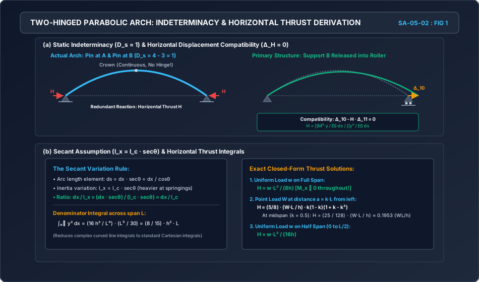
The fundamental mechanics of indeterminate arches revolve around the elastic horizontal reactionH developed at the springing points. In a simply supported curved beam (the primary determinate system), vertical loads cause the two supports to displace horizontally outward. When horizontal movement is rigidly restrained by unyielding abutments, an inward reactive thrust H develops.
Because the structure possesses static indeterminacy, the magnitude of H cannot be determined by equilibrium equations alone (ΣFx=0, ΣFy=0, ΣM=0). Instead, it requires Castigliano’s Second Theorem (or the Principle of Minimum Strain Energy) enforcing compatibility of horizontal boundary displacements (ΔH=0).
2. Statics, Kinematics & Degree of Indeterminacy
2.1 Degree of Static Indeterminacy (Ds)
Consider a two-dimensional planar arch rib supported at both ends A and B:
Two-Hinged Arch:
Support Reactions: Left hinge produces (HA,VA); right hinge produces (HB,VB). Total reactions r=4.
Available Planar Equilibrium Equations: ΣFx=0, ΣFy=0, ΣM=0⟹3.
Special Equations of Condition (Internal Hinges): c=0.
Degree of Indeterminacy:
Ds=r−3−c=4−3−0=1
Physical Redundant: The horizontal thrust H acting between the two abutments.
Fixed Arch:
Support Reactions: Left fixed support (HA,VA,MA); right fixed support (HB,VB,MB). Total reactions r=6.
Internal Hinges: c=0.
Degree of Indeterminacy:
Ds=6−3=3
Physical Redundants: Horizontal thrust H, vertical reaction V, and fixing moment M (typically solved via the Elastic Center Method).
2.2 Sign Conventions & Internal Force Signatures
For any cross-section X(x,y) located at distance x from the left springing A:
Bending Moment (Mx):Mx=Mx0−H⋅y
where Mx0 is the simply supported beam bending moment caused by external gravity loads on a span L, and y is the vertical rise of the rib above the springing line at distance x.
Sagging moment (tension on intrados/bottom): Positive (+).
Hogging moment (tension on extrados/top): Negative (−).
Normal Thrust (Nx):Nx=Hcosθ+Vx0sinθ
where θ is the local inclination of the arch tangent with the horizontal (tanθ=dy/dx), and Vx0 is the vertical shear in the equivalent simply supported beam.
Radial Shear (Qx):Qx=Vx0cosθ−Hsinθ
3. Castigliano’s Second Theorem & Derivation of Horizontal Thrust
Let the horizontal thrust H be chosen as the redundant reaction. The primary determinate structure is a simply supported curved beam with a roller at support B.
3.1 Total Strain Energy Formulation
The total internal strain energy U stored in the arch rib consists of flexural strain energy UM, axial strain energy UN, and shear strain energy UQ:
U=∫0S2EIMx2ds+∫0S2EANx2ds+∫0S2GAksQx2ds
where ds is the elemental arc length along the rib centroidal axis (ds=dx/cosθ=dxsecθ).
In civil engineering arches, the depth-to-span ratio (d/L) is small (<1/15), meaning flexural strain energy overwhelmingly dominates (>95%). Neglecting axial and shear strain energy in the primary formulation (secondary effects are accounted for separately as rib shortening):
U≈∫0S2EIMx2ds
3.2 Compatibility Condition via Castigliano’s Theorem
According to Castigliano’s Second Theorem, the partial derivative of total strain energy with respect to a redundant force equals the displacement at the point and in the direction of that force. For rigid, unyielding abutments:
∂H∂U=ΔH=0
Differentiating under the integral sign:
∂H∂U=∫0SEIMx(∂H∂Mx)ds=0
Substitute Mx=Mx0−H⋅y, whence ∂H∂Mx=−y:
∫0SEIMx0−H⋅y(−y)ds=0
Expanding and rearranging terms:
∫0SEIMx0⋅yds−H∫0SEIy2ds=0
Solving explicitly for the horizontal thrust H:
H=∫0SEIy2ds∫0SEIMx0⋅yds
4. Secant Assumption (Ix=Icsecθ) & Mathematical Integration for Standard Loadings
4.1 The Secant Assumption
Evaluating the integrals along the curved arc length ds is analytically cumbersome because both y and the cross-sectional geometry vary along the profile. To enable closed-form solutions:
Secant Variation of Moment of Inertia:
In real bridge engineering, arch ribs are deepened near the springings to resist higher normal thrusts. Assuming the second moment of area varies as:
Ix=Icsecθ
where Ic is the moment of inertia at the crown (θ=0⟹secθ=1).
Simplifying the Integrand:
Ixds=Icsecθdxsecθ=Icdx
This transforms curved line integrals into standard Cartesian integrals along the span L with constant EIc.
4.2 Parabolic Profile & Denominator Evaluation
For a parabolic arch with span L and central rise h:
y(x)=L24hx(L−x)
The denominator of the horizontal thrust equation evaluates as:
Profound Structural Result:Mx=Mx0−H⋅y=2wx(L−x)−(8hwL2)[L24hx(L−x)]≡0
Under a full UDL, the funicular polygon coincides exactly with the parabolic centerline. Bending moments are zero throughout the arch rib, exactly identical to a three-hinged arch!
Case B: Concentrated Point Load (W) at Distance a=kL from Left Support
(Note: In a three-hinged arch, H=4hWL=0.25hWL. The two-hinged arch thrust is exactly 3225=78.125% of the three-hinged arch thrust!)
Case C: Uniformly Distributed Load (w) Over Half Span (0≤x≤L/2)
By superposition and anti-symmetry of the remaining half:
Hhalf=21Hfull=21(8hwL2)=16hwL2
5. Temperature Effects, Thermal Stresses & Kinematic Restraints
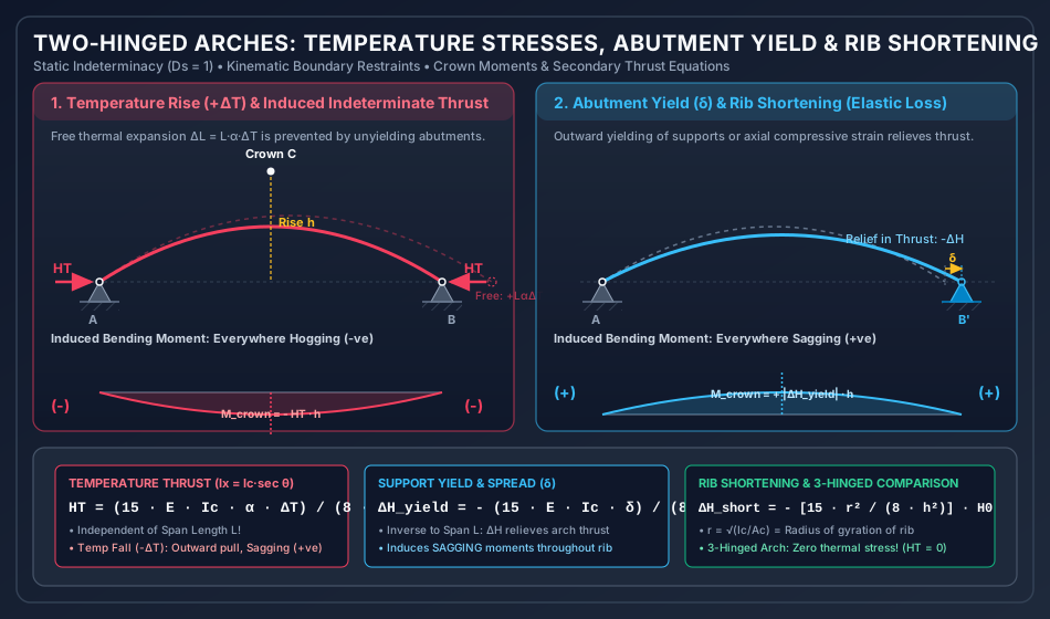
Unlike three-hinged arches where thermal expansion causes free geometric rotation about the crown hinge (σtemp≡0), a two-hinged arch develops severe internal stresses under temperature variations.
5.1 Temperature Rise (+ΔT)
If support B were on rollers, a uniform temperature increase ΔT across the span would cause free horizontal elongation:
ΔLthermal=L⋅α⋅ΔT
where α is the coefficient of thermal expansion of the material.
Because the abutments are unyielding, the net horizontal displacement must remain zero:
Independence of Span Length (L):HT depends only on flexural rigidity EIc, coefficient α, temperature rise ΔT, and inversely on the square of the rise (h2).
Shallow Arch Vulnerability: As rise h decreases, HT∝1/h2, meaning flat, shallow arches experience enormous thermal thrusts!
Induced Bending Moments: Because no gravity loads act (Mx0=0), the bending moment caused by temperature rise is:
Mx=−HT⋅y(x)
This moment is everywhere hogging (negative), reaching its peak magnitude at the crown (y=h):
Mcrown=−HT⋅h=−8h15EIcαΔT
5.2 Temperature Fall (−ΔT)
When the temperature drops, the arch attempts to contract horizontally. The rigid hinges pull the arch outward, inducing:
A negative (tensile) horizontal reaction ΔH=−HT (relieving dead-load thrust).
Induced Moments: Loss of thrust creates sagging bending moments throughout the rib:
ΔMx=−(ΔHyield)⋅y(x)=+(8h2L15EIcδ)y(x)
Maximum sagging at the crown:
ΔMcrown=+8hL15EIcδ
6.2 Rib Shortening (Elastic Axial Shortening)
The compressive normal thrust Nx≈Hcosθ causes the arch rib to shorten elastically along its axis.
The total axial contraction of the rib is:
(assuming Ax=Acsecθ, analogous to the secant assumption).
This axial shortening acts identically to an outward yield of the supports of magnitude δeff=EAcH0L, where H0 is the primary thrust.
Equating boundary compatibility:
ΔHshort(158EIch2L)+EAcH0L=0
Solving for the thrust reduction due to rib shortening:
where r=Ic/Ac is the radius of gyration of the rib cross-section at the crown.
Key Rule of Thumb: In civil engineering arches with h/r≈20 to 40, rib shortening reduces horizontal thrust by approximately 1% to 3%. For very flat arches (h/r<15), the reduction can exceed 5%.
7. Fixed Arches (Ds=3): Elastic Center Method & Temperature Response
A fixed arch has degree of static indeterminacy Ds=3. The redundants are (H,V,M). Solving the three simultaneous equations directly is coupled and tedious. The Elastic Center Method decouples these equations by transferring the origin of coordinates to the centroid of the elastic area of the arch.
7.1 Location of Elastic Center (O)
Let elastic weight ds/EI=dx/EIc.
The coordinates of the elastic center (xˉ,yˉ) measured from the left springing:
Problem 1: Two-Hinged Parabolic Arch Under UDL & Midspan Point Load
Statement:
A two-hinged parabolic arch has a horizontal span L=40 m and a central rise h=8 m. The moment of inertia varies according to the secant law (Ix=Icsecθ). The arch carries a uniformly distributed dead load of 30 kN/m over the entire span, and a concentrated live load of 100 kN at midspan.
Determine:
The total horizontal thrust H.
The bending moment, normal thrust, and radial shear at quarter-span (x=10 m).
Solution:
Step 1: Horizontal Thrust Computation
By the principle of superposition:
Htotal=Hudl+Hpoint
Due to full UDL:
Hudl=8hwL2=8×830×402=6448,000=750.0000 kN
Due to midspan concentrated load:
Hpoint=12825hWL=128×825×100×40=1,024100,000=97.6562 kN
Total Horizontal Thrust:
Htotal=750.0000+97.6562=847.6562 kN
Step 2: Vertical Reactions at Supports
By structural symmetry:
VA=VB=2wL+2W=230×40+2100=600+50=650.0000 kN
Step 3: Geometry and Beam Quantities at Quarter-Span (x=10 m)
Vertical rise y:
y=L24hx(L−x)=4024×8×10×(40−10)=1,60032×300=6.0000 m
Problem 2: Temperature Rise Combined with Abutment Outward Yielding
Statement:
A two-hinged parabolic arch has span L=30 m and central rise h=5 m.
The arch properties are: E=2×10⁵ N/mm2=2×108 kN/m2, Ic=4.5×108 mm4=4.5×10⁻⁴ m4, and α=12×10−6/∘C.
If the temperature rises by ΔT=25∘C, compute the induced horizontal thrust HT and the bending moment at the crown.
If simultaneously one of the abutments yields horizontally outward by δ=6 mm (0.006 m), calculate the relief in thrust ΔHyield and the resulting net crown moment.
Problem 3: Point Load at Quarter-Span & Rib Shortening Loss
Statement:
A two-hinged parabolic arch of span L=30 m and central rise h=6 m carries a concentrated point load W=120 kN at quarter-span (a=7.5 m, k=0.25).
Assuming the secant variation of inertia, find:
The horizontal thrust H.
The bending moment under the load (x=7.5 m) and at the crown (x=15 m).
If the cross-sectional area at the crown is Ac=0.12 m2 and Ic=0.0025 m4, determine the percentage reduction in horizontal thrust due to rib shortening.
Under the Load (x=7.5 m):ya=3024×6×7.5×(30−7.5)=90024×168.75=4.5000 mMa0=VA⋅a=90×7.5=675.0000 kNmMa=Ma0−H⋅ya=675.0000−(83.4961×4.5000)=675.0000−375.7325=+299.2675 kNm(Sagging)
At the Crown (x=15 m):yc=h=6.0000 mMc0=VB×(L−xc)=30×(30−15)=450.0000 kNmMc=Mc0−H⋅yc=450.0000−(83.4961×6.0000)=450.0000−500.9766=−50.9766 kNm(Hogging)
Correction: Under a uniformly distributed load over the entire span, a two-hinged parabolic arch has zero bending moment everywhere (Mx≡0). The funicular line for a UDL is a parabola, which matches the profile exactly. Moments only develop under non-uniform loads (e.g., concentrated loads, partial UDL) or thermal effects.
Misconception 2: "Temperature rise produces sagging moments because the arch expands upward."
Correction: This is the most common exam trap! Temperature rise expands the rib. Because the span length cannot increase due to fixed hinges, an inward horizontal thrust+HT is induced. Since Mx=−HT⋅y, the induced bending moment is negative (hogging) everywhere! The crown fibers experience compression on the extrados (top) and tension on the intrados (bottom).
Misconception 3: "Thermal thrust depends heavily on the bridge span L."
Correction: In the formula HT=8h215EIcαΔT, the span length L completely cancels out! Thermal thrust depends strictly on the central rise h and flexural rigidity EIc. Flat arches with small rise h suffer extreme thermal stresses regardless of whether the span is 20 m or 100 m.
Misconception 4: "Outward yielding of an abutment increases arch stresses."
Correction: Outward yielding δ allows the arch to spread, which relieves horizontal thrust (ΔH<0). However, this loss of thrust reduces the arch action, creating large positive (sagging) bending moments that can overstress the arch rib in flexure.
11. Professional Practice, Codal Specifications & Real-World Bridge Case Studies
11.1 IRC:78 and IS 456 Provisions for Arch Bridges
Temperature Range: In India, IRC:6 mandates design for an overall temperature variation of ±25∘C to ±35∘C depending on the climatic zone.
Differential Temperature Gradient: Bridge decks exposed to direct sunlight heat up more rapidly than the arch rib below. Non-linear vertical temperature gradients induce severe secondary warping moments.
Rib Shortening and Creep: Concrete arches undergo long-term creep and shrinkage strains (4 to 6×10⁻⁴). In long-span reinforced concrete arches, hydraulic flat jacks are inserted at the crown during construction (the Freyssinet Method) to forcibly open the crown and restore the designed thrust before sealing.
11.2 Real-World Case Studies
Sydney Harbour Bridge, Australia:
A two-hinged steel through-arch with span L=503 m and central rise h=134 m.
By eliminating the crown hinge, the bridge achieved enormous aerodynamic and live-load stiffness for heavy commuter rail traffic. The massive pinned bearings at the springings accommodate temperature rotations while resisting a design horizontal thrust of 200,000 kN.
Chenab Rail Bridge, Jammu & Kashmir, India:
The world’s highest railway arch bridge (359 m above river bed), spanning 467 m.
A two-hinged steel trussed arch. Rigorous wind tunnel testing and thermal gradient analyses were conducted to account for Himalayan extreme temperature variations (−20∘C to +40∘C).
12. Comprehensive Summary, Formula Sheet & Fast-Revision Checkpoints
Master Formula Sheet
Horizontal Thrust (General):Secant Law Denominator:Full UDL Across Span:Point Load at Midspan:Point Load at Distance a=kL:Temperature Thrust (2-Hinged):Temperature Thrust (Fixed Arch):Abutment Outward Yield δ:Rib Shortening Thrust Loss:H=∫0SEIy2ds∫0SEIM0yds∫0Ly2dx=158h2L(for y=L24hx(L−x))H=8hwL2,Mx≡0H=12825hWL≈0.1953hWLH=85hWL(k−2k3+k4)HT=8h215EIcαΔT⟹Mcrown=−HT⋅h(Hogging)Hfixed=4h245EIcαΔT=6⋅HT,2-hingedΔHyield=−8h2L15EIcδ(Relief in thrust, induces Sagging)ΔHshort=−8h215r2H0(r=Ic/Ac)
Fast-Revision Key Takeaways
A two-hinged arch is statically indeterminate to the 1st degree (Ds=1).
Under full UDL on a parabolic rib, the bending moment is zero everywhere, identical to a three-hinged arch.
Midspan concentrated load gives thrust H=12825hWL, which is 78.125% of that in a three-hinged arch.
Temperature rise induces inward thrust and hogging moments throughout the rib.
Thermal thrust HT is completely independent of span length L and inversely proportional to h2.
Outward yielding of abutments reduces thrust and causes sagging moments.
In a fixed arch, temperature thrust is 6 times higher than in an equivalent two-hinged arch.