Influence Lines for Trusses & Three-Hinged Arches
In this chapter (4 topics)
On this page
- 1. Module Header & Metadata Block
- 2. Theoretical Foundations & Physical Concepts
- 2.1 Load Transmission in Bridge Trusses
- 2.2 Mechanics of Arch Action vs Flexural Beam Action
- 3. Mathematical Derivations & Analytical Formulations
- 3.1 Influence Lines for Bridge Truss Members
- 3.2 The Counter-Bracing Design Requirement
- 3.3 Influence Lines for Three-Hinged Arches
- 4. Critical Conditions & Governing Theorems
- 4.1 Maximum Forces in Web Diagonals
- 4.2 Maximum Bending Moment in Three-Hinged Arches
- 5. Cross-Sectional & Engineering Schematics
- 5.1 Pratt Truss Member Influence Lines & Stress Reversal
- 5.2 Three-Hinged Arch Mechanics: Thrust & Moment ILDs
- 6. Solved Numerical Examples
- Example 1: Force Envelopes and Counter-Bracing in a Pratt Truss
- Example 2: Bending Moment Envelopes in a Three-Hinged Parabolic Arch
- Example 3: Normal Thrust and Radial Shear in a Three-Hinged Arch
- 7. Engineering Design Applications & Field Practice
- 7.1 Modern Railway Truss Bridge Design
- 7.2 Steel Arch Bridges & Line of Thrust
- 8. Comparative Analysis & Summary Matrix
- 8.1 Comparison of Truss Members vs Flexural Beam Elements
- 8.2 Comparison of Arch Types Under Moving Loads
- 9. Common Misconceptions & Exam Pitfalls
- 10. Previous Years' Examination Analysis & Reference Questions
- 10.1 Representative Exam Problems
- 11. Practice Problems with Answer Keys
- Problem 1 (Truss Bottom Chord ILD)
- Problem 2 (Three-Hinged Arch Horizontal Thrust)
- Problem 3 (Arch Radial Shear Jump)
- 12. Comprehensive Subject & Examination Mapping
1. Module Header & Metadata Block
- Topic ID:
SA-04-03 - Module: Structural Analysis (Subject 03)
- Chapter: Chapter 04: Influence Line Diagrams & Moving Loads
- Title: Influence Lines for Trusses & Three-Hinged Arches
- Target Examinations:
- GATE Civil Engineering (Structural Engineering)
- UPSC Engineering Services Examination (ESE/IES Paper-I)
- SSC JE Civil Engineering (Theory of Structures)
- State Public Service Commission Assistant Engineer (AE) & Junior Engineer (JE) Examinations
- Railway Recruitment Board Junior Engineer (RRB JE)
- Prerequisites:
- Topic
SA-01-01: Static Indeterminacy of Trusses & Arches - Topic
SA-04-01: Influence Lines for Determinate Beams & Girders - Topic
SA-04-02: Moving Loads & Maximum Internal Force Envelopes
- Topic
- Learning Objectives:
- Construct Influence Line Diagrams (ILD) for chord, vertical, and diagonal web members of planar bridge trusses (Pratt, Warren, and Howe trusses).
- Formulate the condition of stress reversal in truss web members and determine the design criteria for counter-bracing.
- Derive the influence lines for reactions, horizontal thrust (), bending moment (), normal thrust (), and radial shear () in three-hinged parabolic and circular arches.
- Prove analytically why a three-hinged parabolic arch experiences zero bending moment under a uniformly distributed load covering the entire span.
- Solve complex competitive examination problems involving moving vehicular train loads on bridge trusses and arches.
2. Theoretical Foundations & Physical Concepts
2.1 Load Transmission in Bridge Trusses
In truss bridges, moving vehicular traffic does not ride directly on the truss chords or web members. Instead, a specialized floor framing system is utilized:
- Bridge Deck (Slab / Timber): Carries the wheel loads directly.
- Stringers (Longitudinal Beams): Support the deck and span parallel to the bridge axis between adjacent floor beams.
- Floor Beams (Transverse Girders): Span transversely between the trusses and connect to the truss nodes (panel points).
- Main Trusses: Receive concentrated panel point reactions transmitted through the floor beam connections.
Consequently, as a unit load moves across a panel, it is distributed between the adjacent joints by simple lever action (indirect loading).
  Top Chord       U1 -------- U2 -------- U3 -------- U4
                  /| \      / |\ \      / |\ \      / |\
                 / |  \    /  | \ \    /  | \ \    /  | \
  Bottom Chord  L0---L1-------L2-------L3-------L4----L5
                     ^        ^        ^        ^
               [Floor Beams Connect at Panel Points Only]
Classification of Trusses by Deck Location:
- Through Truss: Traffic travels between the trusses along the bottom chord. The bottom chord panel points receive the live loads.
- Deck Truss: Traffic travels on top of the trusses along the top chord. The top chord panel points receive the live loads.
- Pony Truss (Half-Through Truss): Traffic travels along the bottom chord, but the truss depth is too shallow to permit overhead lateral sway bracing.
2.2 Mechanics of Arch Action vs Flexural Beam Action
A beam resists transverse gravity loading exclusively by internal bending moments and transverse shear forces, resulting in large flexural stresses and significant deflections across long spans.
An arch introduces inclined thrust reactions at its supports. The horizontal thrust () acts inward against the abutments:
where:
- is the bending moment that would exist in a simply supported beam of the same span carrying the identical load.
- is the vertical rise of the arch rib above the support level at section .
- is a relieving hogging moment produced by the horizontal thrust.
In an ideal parabolic arch carrying a full uniformly distributed load, and .
The internal bending moment is identically zero throughout the entire span, and the arch rib is subjected purely to direct axial compression!
3. Mathematical Derivations & Analytical Formulations
3.1 Influence Lines for Bridge Truss Members
Consider a Pratt through-truss bridge of span , consisting of panels of width () and constant height . Live loads move along the bottom chord.
          U1           U2           U3           U4
          o------------o------------o------------o
         /|          / |          / | \          |\
        / |         /  |         /  |  \         | \
       /  |        /   |        /   |   \        |  \
      o---o--------o---o--------o---o----o-------o---o
     L0   L1       L2           L3       L4      L5  L6
(a) Influence Line for Chord Members (Method of Sections)
To determine the force in a chord member, pass a vertical cutting section through the panel containing the member, and take moments about the moment center (the opposite joint where the remaining cut members intersect).
-
Top Chord Member ( in Panel ):
- Pass section through , diagonal , and bottom chord .
- The two unknown cut members ( and ) intersect at bottom joint ().
- Taking moments about joint :
- Conclusion: The ILD for top chord member is directly proportional to the simply supported beam bending moment ILD at joint , scaled by .
- Characteristics:
- Entirely negative (Compression).
- Triangular shape with zero at and , and peak ordinate at joint :
-
Bottom Chord Member ( in Panel ):
- The two other cut members ( and ) intersect at top joint ().
- Taking moments about joint :
- Conclusion: The ILD for bottom chord member is directly proportional to the beam moment ILD at joint , scaled by .
- Characteristics:
- Entirely positive (Tension).
- Triangular shape with peak ordinate at joint :
(b) Influence Line for Diagonal Web Members & Stress Reversal
Consider diagonal member inclined at angle to the horizontal ().
Pass a vertical cutting section through panel . Vertical equilibrium requires:
where is the transverse vertical shear in panel .
From SA-04-01, the shear in panel under indirect loading is:
-
When unit load is at or to the left of joint ():
Peak positive value occurs at joint ():
-
When unit load is at or to the right of joint ():
Peak negative value occurs at joint ():
-
Between joints and (Inside Panel ): The ILD is a straight line connecting () and (). The line crosses zero at distance from the left support:
Specifically, the zero-crossing point divides panel width into:
     + Tension
         ^            /---\ (Peak at L2 = +2 / n*sinθ)
         |           /     \
    -----0----------+-------+--------0-----> Joint x
         |          0       | \     /
         |                  |  \---/ (Peak at L3 = -(n-3) / n*sinθ)
         v - Compression    Zero Point (x_0)
3.2 The Counter-Bracing Design Requirement
Because the ILD for web diagonal has both a positive (tension) lobe and a negative (compression) lobe:
- When live load occupies the left approach (), the member is subjected to tension.
- When live load occupies the right approach (), the member is subjected to compression.
In historic and lightweight bridge designs, diagonals were constructed of slender flat bars, eye-bars, or thin angles. These members have high slenderness ratios () and negligible compressive capacity—they buckle elastically under minute compressive loads.
Criterion for Providing Counter-Bracing
Let:
- Dead load force in diagonal member (typically tensile, ).
- Maximum live load tensile force ().
- Maximum live load compressive force ().
The governing design load combinations:
[!IMPORTANT] Statutory Condition for Stress Reversal & Counter-Bracing: If the dead load tension is smaller in magnitude than the maximum live load compression:
the diagonal member experiences a net compressive force! To prevent buckling failure, a second diagonal member called a counter-brace () is introduced in the same panel, running in the opposite diagonal direction.
- Under primary loading: is in tension; counter-brace goes slack.
- Under reversed loading: buckles harmlessly / goes slack; counter-brace develops tension and carries the panel shear safely!
3.3 Influence Lines for Three-Hinged Arches
Consider a three-hinged arch with supports () and (), and an internal crown hinge at ().
                      Crown Hinge C (h)
                             o
                           /   \
                          /     \
                         /       \
                        /         \
    Pin A o------------+-----------+------------o Pin B
         x=0         Section D                 x=L
(a) Support Reactions
- Vertical Reactions (): Identical to a simply supported beam:
- Horizontal Thrust ():
The internal crown hinge condition requires .
- Load on Left Half (): Consider equilibrium of right half segment :
- Load on Right Half (): Consider equilibrium of left half segment :
[!IMPORTANT] Geometric Independence of Horizontal Thrust ILD: The ILD for horizontal thrust in a three-hinged arch is a symmetric triangle with:
- Zero at supports () and ().
- Maximum ordinate at the crown ():
Crucial Fact: This formula depends only on span and central rise ; it is completely independent of the profile shape of the arch rib (parabolic, segmental, circular, or elliptical)!
(b) Bending Moment at Any Cross-Section ()
The bending moment at cross-section located at distance from () is:
where:
- is the triangular moment ILD for a simply supported beam at (peak at ).
- is the horizontal thrust ILD scaled by the vertical ordinate .
Superposition Coordinates:
- At support (): .
- Under Section ():
- Under Crown ():
- Zero-Crossing Point (): Occurs between and where .
(c) The Zero-Moment Balance Theorem for Parabolic Arches
In a parabolic arch with profile :
The net area under the bending moment ILD over the entire span is:
Evaluating the two components:
- Area of beam moment ILD:
- Area of ILD:
- Relieving thrust area:
[!NOTE] The Zero-Moment Balance Theorem: In any three-hinged parabolic arch, the positive area of the bending moment ILD exactly equals the negative area. Consequently, a uniformly distributed load covering the entire span produces zero bending moment at every cross-section!
(d) Normal Thrust () and Radial Shear () at Section
At cross-section , let the tangent to the arch rib make an angle with the horizontal:
The internal resultant forces acting on the inclined cut section are:
- Normal Thrust (): Component parallel to the arch rib axis (direct axial compression).
- Radial Shear (): Component perpendicular to the arch rib axis.
where is the vertical shear force at section ( for ; for ).
Jump Discontinuities as Load Crosses Section :
- Jump in Vertical Shear:
- Jump in Normal Thrust:
- Jump in Radial Shear:
4. Critical Conditions & Governing Theorems
4.1 Maximum Forces in Web Diagonals
- Maximum Tension: Position the live load to cover only the positive segment of the ILD (from left support to zero-crossing point ).
- Maximum Compression: Position the live load to cover only the negative segment of the ILD (from to right support ).
4.2 Maximum Bending Moment in Three-Hinged Arches
- Maximum Positive (Sagging) Moment at Section : Place rolling loads exclusively on the positive lobe of the ILD (between and the inflection point ).
- Maximum Negative (Hogging) Moment at Section : Place rolling loads exclusively on the negative lobe of the ILD (between and , centered near the crown).
5. Cross-Sectional & Engineering Schematics
5.1 Pratt Truss Member Influence Lines & Stress Reversal
The following engineering drawing illustrates the ILD for top chord, bottom chord, and diagonal web members of a Pratt truss, highlighting the stress reversal in web members:
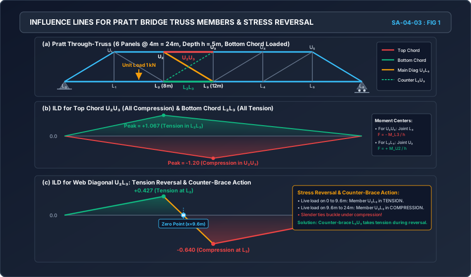
5.2 Three-Hinged Arch Mechanics: Thrust & Moment ILDs
The following schematic details the horizontal thrust and bending moment influence lines for a three-hinged parabolic arch, illustrating the zero-moment balance theorem:
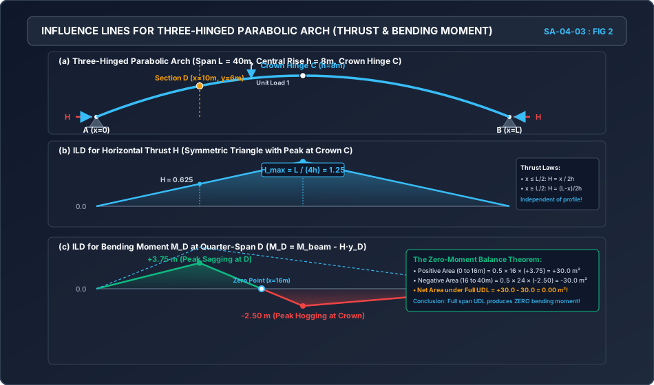
6. Solved Numerical Examples
Example 1: Force Envelopes and Counter-Bracing in a Pratt Truss
Problem Statement: A through-type Pratt bridge truss has a span of divided into 6 equal panels of . The depth of the truss is constant at . Dead load transmits an equivalent bottom chord panel point load of at each intermediate joint ( to ). A live load train consisting of a uniformly distributed load of and length longer than the span rolls across the bridge.
For member in panel :
- Determine the influence line ordinates at all panel points and find the zero-crossing inflection point.
- Calculate the dead load force in member .
- Calculate the maximum live load tensile force and compressive force.
- Determine whether stress reversal occurs, and state if a counter-brace is required.
       U1           U2           U3           U4           U5
       o------------o------------o------------o------------o
      /|          / |          / |          / |          / | \
     / |         /  |         /  |         /  |         /  |  \
    o--o--------o---o--------o---o--------o---o--------o---o---o
   L0  L1       L2  L3       L4  L5       L6
   0   4        8   12       16  20       24m
Solution:
Step 1: Member Geometry
- Panel width , Height .
- Diagonal length .
- Angle with horizontal: .
Step 2: Influence Line Ordinates for Diagonal
Pass a section through panel (between and ). Vertical equilibrium: .
-
Unit load at joint ():
-
Unit load at joint ():
-
Zero-Crossing Point (): The line connects to across the panel:
Step 3: Dead Load Force in
Dead loads of act at joints :
- At ():
- At ():
- At ():
- At ():
- At ():
Sum of ILD ordinates at loaded joints:
(Note: Panel in a 6-panel truss has dead load compression because it lies in the center bay!)
Step 4: Maximum Live Load Forces
-
Maximum Live Load Tension (): Occurs when UDL covers the positive lobe ( to ):
Direct triangle area: Base , peak height at is :
-
Maximum Live Load Compression (): Occurs when UDL covers the negative lobe ( to ):
Peak height at is :
Step 5: Stress Reversal & Counter-Bracing Evaluation
- Total Maximum Tension in :
- Total Maximum Compression in :
Conclusion: Member experiences severe stress reversal (from tension to compression). A slender tension diagonal cannot resist of compression without buckling. Therefore, counter-bracing () MUST be provided in panel , designed to carry of tension when the primary diagonal goes slack!
Example 2: Bending Moment Envelopes in a Three-Hinged Parabolic Arch
Problem Statement: A three-hinged parabolic arch has a clear span of and a central rise of . A moving uniformly distributed live load of intensity and of any length crosses the arch. For a cross-section located at quarter-span ( from left abutment ):
- Derive the influence line equation for bending moment and calculate ordinates at , (crown), and the zero-crossing inflection point.
- Determine the maximum positive (sagging) bending moment at section .
- Determine the maximum negative (hogging) bending moment at section .
- Verify that a full-span UDL produces zero bending moment at section .
Solution:
Step 1: Geometry & ILD Ordinates
-
Arch equation: .
-
At : .
-
Arch thrust equation:
- : .
- : .
- Peak at crown (): .
-
Bending moment at section : .
- At :
- At Crown :
- Zero-Crossing Point (): In the interval :
Step 2: Maximum Positive (Sagging) Moment at Section
To maximize positive moment, load covers the positive lobe ( to ):
Step 3: Maximum Negative (Hogging) Moment at Section
To maximize negative moment, load covers the negative lobe ( to ):
- Base .
- Negative peak ordinate at is .
Step 4: Verification under Full Span UDL
When UDL covers the entire span ( to ):
Q.E.D. The Zero-Moment Balance Theorem is fully verified!
Example 3: Normal Thrust and Radial Shear in a Three-Hinged Arch
Problem Statement: For the same arch (, , section at ): Determine:
- The slope of the arch axis and the values of and .
- The step discontinuities (jumps) in Normal Thrust () and Radial Shear () as a unit load passes from to .
- The normal thrust and radial shear developed at section when a single concentrated load of is placed directly at the crown hinge ().
Solution:
Step 1: Slope and Trigonometric Functions at Section
Step 2: Jump Discontinuities at Section
As a unit rolling load crosses section , the vertical shear jumps by .
- Jump in Normal Thrust:
- Jump in Radial Shear:
Step 3: Normal Thrust and Radial Shear with Load at Crown
When load is at the crown ():
- Vertical Shear at Section (): The load is to the right of section (). By beam statics, right reaction , left reaction . Shear force to the left of the load at section :
- Horizontal Thrust :
- Normal Thrust :
- Radial Shear :
Remarkable Engineering Insight: When the load is placed at the crown hinge, the radial shear at quarter-span is identically zero! The entire internal resistance is pure axial compression ().
7. Engineering Design Applications & Field Practice
7.1 Modern Railway Truss Bridge Design
In Indian Railways open-web girder bridges (Standard 30.5m, 45.7m, 61.0m, and 76.2m spans designed per IRS Bridge Rules):
- Modern bridge codes prohibit the use of slender tension-only counter-braces because dynamic train impacts induce severe vibration, fatigue, and joint rattling.
- Instead, all web members are designed as rigid beam-column members (fabricated box sections or rolled H-shapes with batten plates or lacing) capable of resisting both tension and compression reversals per IS:800 and IRS Steel Bridge Code.
7.2 Steel Arch Bridges & Line of Thrust
In long-span steel arches (such as the Chenab Rail Bridge or Sydney Harbour Bridge):
- The parabolic profile is chosen because dead loads (concrete deck, ballast, cross-girders) form an approximately uniform gravity load.
- Because dead load produces near-zero bending moment in a parabolic arch, the arch rib experiences minimal flexural stress under permanent state.
- Bending moments only develop under asymmetric, transient live loads (moving train on one half of the span). The influence line positive and negative lobes dictate the required section modulus of the arch rib.
8. Comparative Analysis & Summary Matrix
8.1 Comparison of Truss Members vs Flexural Beam Elements
| Property / Feature | Truss Chord Members | Truss Web Diagonals | Beam SFD / BMD Element |
|---|---|---|---|
| Equivalent Beam Action | Resists Global Bending Moment () | Resists Global Transverse Shear () | Internal and |
| ILD Shape | Purely Triangular, Single Sign (all or all ) | Segmented, Changes Sign (both and lobes) | Triangular (), Stepped () |
| Stress Reversal? | No (Bottom chord always tension; top chord always compression) | Yes (Subject to tension and compression depending on train position) | Bending moment is single sign; shear reverses |
| Special Design Measure | Standard tension / compression sizing | Counter-Bracing or rigid compression sizing | Web stiffeners, stirrups |
8.2 Comparison of Arch Types Under Moving Loads
| Arch Structural Type | Static Indeterminacy () | Horizontal Thrust ILD Peak () | Temperature / Settlement Stresses |
|---|---|---|---|
| Three-Hinged Arch | (Statically Determinate) | (at crown) | Zero (Hinges rotate freely without internal stress) |
| Two-Hinged Arch | (Indeterminate to 1st degree) | High thermal thrust stresses; sensitive to abutment spread | |
| Fixed Arch (Hingeless) | (Indeterminate to 3rd degree) | Extremely sensitive to temperature drops and support rotation |
9. Common Misconceptions & Exam Pitfalls
[!CAUTION] Trap 1: Assuming Counter-Bracing is Needed in Every Panel
Students often assume counter-bracing is required throughout the entire truss span.
Reality: Near the bridge ends (panels ), the dead load shear is so massive that the live load reversal cannot overcome it (). Counter-braces are only required in the central panels where dead load shear is near zero!
[!WARNING] Trap 2: Forgetting That Arch Thrust ILD is Independent of Rib Shape
Questions often state: "Determine the peak horizontal thrust in a three-hinged circular arch of span and rise ." Students spend minutes attempting complicated circular trigonometry.
Reality: Taking moments about the crown hinge proves that for any three-hinged arch, regardless of whether it is parabolic, circular, or elliptical!
[!WARNING] Trap 3: Neglecting Indirect Loading at Intermediate Truss Joints
Drawing a diagonal web member ILD with a sharp vertical jump at the panel point (like a beam shear ILD).
Reality: Because floor beams only connect at panel points, the ILD inside the panel is a smooth, continuous sloping chord connecting the two joint ordinates. There is never a vertical step in a truss ILD!
10. Previous Years' Examination Analysis & Reference Questions
10.1 Representative Exam Problems
Question 1 (GATE Civil Engineering)
For a three-hinged parabolic arch of span and central rise , the influence line diagram for horizontal thrust at the supports is:
- (A) Parabolic with maximum ordinate at midspan
- (B) Triangular with maximum ordinate of at midspan
- (C) Trapezoidal with maximum ordinate of
- (D) Rectangular of height Solution: Option (B).
Question 2 (UPSC ESE / IES)
In a Pratt truss, the web diagonal members are normally oriented such that under dead loads they are subjected to:
- (A) Compression
- (B) Tension
- (C) Bending
- (D) Pure shear Solution: Option (B). In a Pratt truss, diagonals lean towards the center and carry tension under gravity loads, while verticals carry compression.
Question 3 (SSC JE / State AE)
Under a uniformly distributed load covering the entire span of a three-hinged parabolic arch, the bending moment at any section of the arch is:
- (A) Maximum at quarter span
- (B) Maximum at crown
- (C) Zero throughout the span
- (D) Proportional to the rise of the arch Solution: Option (C).
11. Practice Problems with Answer Keys
Problem 1 (Truss Bottom Chord ILD)
A Warren through-truss with vertical members has 6 panels of each () and a height of . Calculate the maximum tensile force developed in bottom chord member when a single moving wheel load of crosses the bridge.
Answer Key:
- Moment center for is top joint ().
- Peak beam moment ordinate at : .
- Chord force ILD peak: .
- Maximum force: (Tension).
Problem 2 (Three-Hinged Arch Horizontal Thrust)
A three-hinged arch has a span of and a central rise of . A moving train of two axle loads of and spaced apart crosses the arch. Determine the maximum horizontal thrust developed at the supports.
Answer Key:
- Peak ILD ordinate at crown (): .
- Slopes of ILD: .
- Place heavier load () at crown (, ordinate ).
- Trailing load () is at (ordinate ).
- Total thrust: .
Problem 3 (Arch Radial Shear Jump)
A three-hinged parabolic arch has span and rise . At section located from the left support, compute the jump in radial shear as a unit load passes the section.
Answer Key:
- Slope at :
- Jump in radial shear: .
12. Comprehensive Subject & Examination Mapping
| Competitive Examination | Relevant Section / Paper | Expected Weightage | Typical Question Style |
|---|---|---|---|
| GATE CE | Structural Engineering (Analysis) | Numerical problems on truss member ILD peak ordinates, zero-moment in parabolic arches, or arch thrust under rolling loads. | |
| UPSC ESE | Paper-I (Structural Analysis) | Derivation of counter-bracing criteria, stress reversal calculation, and ILD for normal thrust and radial shear. | |
| SSC JE | Theory of Structures | Direct formula identification: , Pratt vs Howe diagonal behavior, zero moment under full UDL. | |
| State AE / JE | Civil Engineering Paper-I | Calculation of horizontal thrust under point load and location of zero-crossing point in truss diagonals. | |
| RRB JE | Structural Mechanics | Basic conceptual definitions of three-hinged arch determinacy, crown hinge condition, and truss panel load paths. |