Plastic Hinges, Plastic Moment Capacity () & Shape Factor ()
In this chapter (4 topics)
On this page
- 1. Introduction & Conceptual Foundations
- 1.1 The Elastic Paradigm vs. The Plastic Paradigm
- 1.2 Idealized Stress-Strain Relationship
- 2. Core Engineering Principles & Fundamental Assumptions
- 3. Mathematical Derivations: From Yield Moment to Full Plastic Moment
- 3.1 The Elastic Neutral Axis (ENA) vs. Plastic Neutral Axis (PNA)
- 3.2 Yield Moment (My) and Elastic Section Modulus (Ze)
- 3.3 Plastic Moment Capacity (Mp) and Plastic Section Modulus (Zp)
- 3.4 The Shape Factor (S)
- 3.5 Load Factor (Q) and Margin of Safety
- 4. Exact Formulations for Standard Structural Cross-Sections
- Derivation for Solid Diamond (Rhombus)
- Derivation for Solid Circle
- 5. Length of Plastic Hinge & Moment-Curvature (M-φ) Relationship
- 5.1 Moment-Curvature Relationship (M-φ)
- 5.2 Definition & Mathematical Formulation of Plastic Hinge Length (Lp)
- 6. Practical Engineering Applications & Codal Provisions (IS 800:2007)
- 7. Worked Numerical Examples
- Problem 1: Unsymmetric T-Section (ENA vs PNA, Ze, Zp, and Shape Factor)
- Problem 2: Built-Up Symmetric I-Section (IS 800 Class Check & Shape Factor)
- Problem 3: Length of Plastic Hinge (Point Load vs. UDL Comparison)
- 8. Common Misconceptions & Exam Pitfalls
- 9. Comparative Summary & Formula Matrix
- 10. Practice Questions & Competitive Examination Problems
- Multiple Choice & Objective Questions
- 11. References & Code Standards
1. Introduction & Conceptual Foundations
1.1 The Elastic Paradigm vs. The Plastic Paradigm
Classical structural analysis relies predominantly on linear elastic behavior governed by Hooke's law (). Under the allowable stress design (ASD) or working stress method (WSM), a structural element is considered to have reached its capacity as soon as the extreme outer fiber stress reaches the yield stress of the material ().
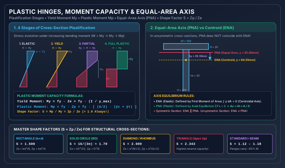
However, ductile structural steel possesses a profound reserve of strength beyond initial yielding. Once the outer fibers yield, they do not rupture; instead, they undergo plastic flow at approximately constant stress while interior fibers, which are stressed below , continue to take on additional bending moment until the entire cross-section is plastically yielded. This phenomenon forms the foundation of Plastic Analysis (or Limit State Design / Ultimate Load Theory).
   Elastic Theory (WSM): Capacity reached when sigma_max = f_y (Yield Moment M_y)
   Plastic Theory (USM): Capacity reached when all fibers reach f_y (Plastic Moment M_p)
   Reserve Margin = (M_p - M_y) / M_y = (Shape Factor - 1) * 100%
1.2 Idealized Stress-Strain Relationship
Plastic analysis of structural steel is based on the idealized rigid-perfectly plastic or elastic-perfectly plastic stress-strain material model (Prandtl's body):
- Linear Elastic Region (): .
- Plastic Yield Plateau (): (constant yield plateau, typically spanning strains up to to before strain hardening commences).
- Strain Hardening Neglect: Strain hardening is conservatively ignored in standard plastic collapse design, ensuring an inherent additional factor of safety against total collapse.
2. Core Engineering Principles & Fundamental Assumptions
Plastic analysis is governed by six fundamental assumptions:
- Navier-Bernoulli Hypothesis (Planar Strains): Cross-sections that are plane before bending remain plane after bending across both the elastic and fully plastic regimes. Consequently, the longitudinal strain distribution across the depth is strictly linear: where is the curvature and is the distance from the neutral axis.
- Idealized Elastic-Plastic Stress-Strain Relationship: The material exhibits symmetrical behavior in tension and compression with a well-defined yield stress and modulus of elasticity .
- Equal Tension and Compression Yield: .
- Neglect of Secondary Effects: Axial force, shear force, and torsional stresses are initially assumed negligible (or accounted for via interaction equations) so that failure occurs strictly in flexure.
- No Local or Lateral-Torsional Buckling: The structural steel section is assumed to be "Plastic" or "Compact" (Class 1 or Class 2 per IS 800:2007, Table 2), ensuring that local flange/web buckling or lateral-torsional instability does not occur prior to full plastic hinge rotation.
- Deflections are Small: Deflections prior to plastic collapse are sufficiently small so that the initial undeformed geometry can be used for equilibrium equations.
3. Mathematical Derivations: From Yield Moment to Full Plastic Moment
3.1 The Elastic Neutral Axis (ENA) vs. Plastic Neutral Axis (PNA)
Elastic Neutral Axis (ENA)
In the elastic regime, the stress at distance from the neutral axis is . Axial equilibrium requires:
Hence, the Elastic Neutral Axis (ENA) passes through the geometric centroid of the cross-section.
Plastic Neutral Axis (PNA)
When the entire cross-section has yielded, the tensile fibers carry stress and the compressive fibers carry stress . Axial force equilibrium under pure flexure requires:
Fundamental Theorem: The Plastic Neutral Axis (PNA) is the Equal-Area Axis of the cross-section. For symmetrical sections, the PNA coincides with the ENA (centroid). For unsymmetrical sections (e.g., T-sections, unsymmetrical I-sections), the PNA does not pass through the centroid.
3.2 Yield Moment () and Elastic Section Modulus ()
The yield moment is the bending moment at which the outermost fiber first reaches yield stress :
where:
- is the second moment of area about the centroidal ENA.
- is the distance from the ENA to the most remote outer fiber.
- is the elastic section modulus ().
3.3 Plastic Moment Capacity () and Plastic Section Modulus ()
At full plastic yield, every fiber above the PNA is in compression at , and every fiber below the PNA is in tension at . The internal resisting couple is:
Since :
where:
- is the distance from the PNA to the centroid of the compressive area .
- is the distance from the PNA to the centroid of the tensile area .
- is the Plastic Section Modulus.
- is the lever arm between the resultant plastic compressive and tensile forces:
3.4 The Shape Factor ()
The Shape Factor () is a dimensionless geometric property of a cross-section defined as the ratio of its plastic moment capacity to its yield moment capacity:
Physical Significance of Shape Factor
- Reserve Strength: The quantity indicates the percentage increase in flexural load-carrying capacity from the onset of yielding to complete plastification.
- Cross-Sectional Efficiency: Sections with mass concentrated near the neutral axis (e.g., diamonds, triangles) have high shape factors ( to ), meaning low elastic efficiency but high plastic reserve. Sections with mass concentrated far from the neutral axis (e.g., I-beams) have low shape factors (), meaning high elastic efficiency and a smaller plastic reserve.
3.5 Load Factor () and Margin of Safety
- Load Factor ( or ): Ratio of collapse load () to working load ():
- In statically determinate beams, the plastic collapse occurs at the formation of a single plastic hinge: where .
4. Exact Formulations for Standard Structural Cross-Sections
The table below summarizes the exact mathematical formulas for centroid, PNA, , , and Shape Factor across canonical engineering cross-sections:
| Cross-Section Geometry | Dimensions | Elastic Section Modulus | Plastic Section Modulus | Shape Factor | Reserve Capacity |
|---|---|---|---|---|---|
| Solid Rectangle | Width , Depth | ||||
| Solid Circle | Diameter | ||||
| Thin Circular Ring | Mean Dia , thickness | ||||
| Solid Diamond (Rhombus) | Diagonals (axis along ) | ||||
| Isosceles Triangle (Apex Up) | Base , Height (axis ) | ||||
| Standard Wide-Flange I-Beam | , flange , web | ||||
| Thin-Walled Tube (Square) | Outer , thickness |
Derivation for Solid Diamond (Rhombus)
For a diamond of width and height with horizontal neutral axis:
- Area .
- .
- .
- For plastic modulus: Half-area above NA is a triangle of base and height .
- Area .
- Centroid .
- .
- Shape Factor:
Derivation for Solid Circle
- Area . .
- .
- Half-area above NA is a semicircle: .
- Centroid of semicircle from diameter: .
- .
- Shape Factor:
5. Length of Plastic Hinge & Moment-Curvature () Relationship
5.1 Moment-Curvature Relationship ()
The curvature of a beam is related to the extreme fiber strain by .
- Elastic Stage ():
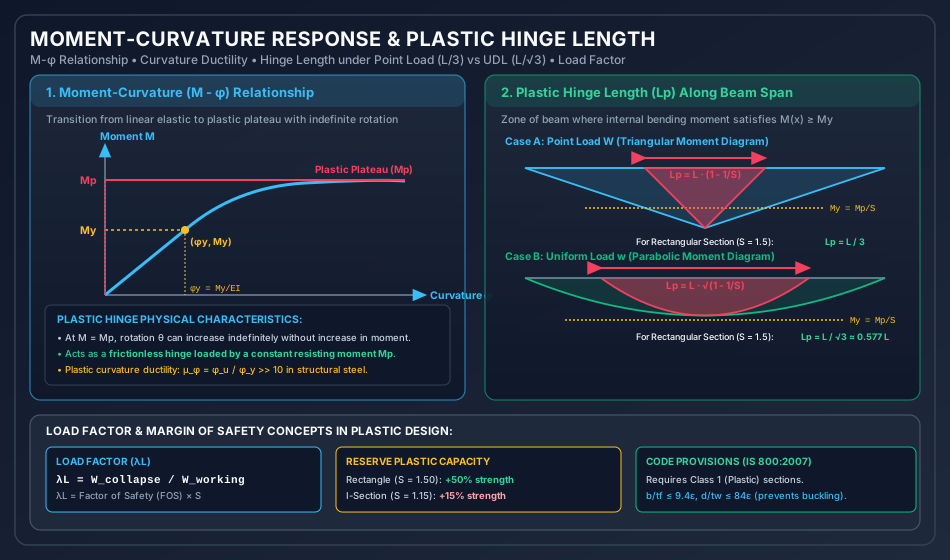
- Elasto-Plastic Stage (): Yielding penetrates inward from outer fibers to depth . For a rectangular section: As , .
- Fully Plastic Stage (): The section undergoes rotation at constant moment . It acts as a Plastic Hinge, permitting infinite rotation (theoretically) while sustaining .
5.2 Definition & Mathematical Formulation of Plastic Hinge Length ()
In a real beam subjected to distributed or point loads, the bending moment varies along the span. The fully plastic moment occurs at the section of maximum moment. However, all adjacent cross-sections where the bending moment exceeds the yield moment () undergo partial yielding (elasto-plastic deformation).
The physical zone along the span where is termed the Length of the Plastic Hinge ().
Case A: Simply Supported Beam with Central Concentrated Load
At collapse, the mid-span moment reaches . The bending moment varies linearly:
At the boundary of the plastic zone, :
The yielding extends on both sides of the center:
- For a Rectangular Section ():
- For an I-Section ():
Case B: Simply Supported Beam with Uniformly Distributed Load
At collapse, the mid-span moment reaches . The bending moment equation referenced from mid-span ( at mid-span, ) is:
At the boundary of the plastic zone, :
Since :
- For a Rectangular Section ():
- For an I-Section ():
6. Practical Engineering Applications & Codal Provisions (IS 800:2007)
- Classification of Cross-Sections (IS 800:2007, Clause 3.7):
- Class 1 (Plastic): Cross-sections can develop plastic moment capacity and possess sufficient rotation capacity () to form a plastic mechanism. Only Class 1 sections are permitted for plastic analysis.
- Class 2 (Compact): Cross-sections can develop but have limited rotation capacity due to local buckling. Allowed in elastic analysis with limit state design, but not for plastic redistribution.
- Class 3 (Semi-Compact): Extreme fiber reaches (), but local buckling prevents development of .
- Class 4 (Slender): Local buckling occurs before the yield stress is reached in extreme fibers.
- Width-to-Thickness Ratio Limits (, ):
For rolled I-sections to qualify as Class 1 (Plastic):
- Flange projection: , where .
- Web under neutral axis at mid-depth: .
- Effect of High Shear Force on Plastic Moment Capacity (Clause 9.2.2): When the factored shear force , the plastic moment capacity is unaffected (). When ("High Shear"): where and is the plastic moment capacity of the flanges only.
7. Worked Numerical Examples
Problem 1: Unsymmetric T-Section (ENA vs PNA, , , and Shape Factor)
Statement: A structural steel T-section has a flange of and a web of . The steel yield strength is .
- Determine the position of the Elastic Neutral Axis (ENA) and the Plastic Neutral Axis (PNA) from the top fiber.
- Calculate the elastic section modulus () and yield moment ().
- Calculate the plastic section modulus () and plastic moment capacity ().
- Compute the Shape Factor () and the shift between ENA and PNA ().
        <--------- 150 mm --------->
       +----------------------------+  ^ 20 mm
       |          Flange            |  v
       +------------+---+-----------+
                    |   |
                    | W |
                    | e |  180 mm
                    | b |
                    |   |  (Width = 20 mm)
                    +---+
Solution:
Step 1: Total Area and Location of Elastic Neutral Axis (ENA)
- Flange Area: , centroid from top: .
- Web Area: , centroid from top: .
- Total Area: .
- Centroid from top fiber ():
- Distance to bottom fiber: Since , .
Step 2: Moment of Inertia () and Elastic Modulus () Using the parallel axis theorem:
- Flange:
- Web:
- Total :
- Elastic Section Modulus ():
- Yield Moment:
Step 3: Location of Plastic Neutral Axis (PNA) The PNA divides the section into two equal areas: .
- Flange area is , hence the PNA must lie within the web.
- Let be the depth into the web from the junction of flange and web:
- Distance of PNA from top fiber:
- Shift between ENA and PNA:
Step 4: Plastic Section Modulus () and Plastic Moment () Taking first moments of area about the PNA:
- Compression zone (above PNA, depth ):
- Flange (): area , lever arm to PNA .
- Web portion (): area , lever arm to PNA .
- Compressive first moment:
- Tension zone (below PNA, depth ):
- Remaining web (): area , lever arm to PNA .
- Tensile first moment:
- Total Plastic Section Modulus:
- Plastic Moment Capacity:
Step 5: Shape Factor ()
(The section possesses an 80.81% reserve flexural strength beyond elastic yield).
Problem 2: Built-Up Symmetric I-Section (IS 800 Class Check & Shape Factor)
Statement: A built-up I-girder consists of two flange plates of and a web plate of . Total overall depth is . Yield stress .
- Verify the section classification per IS 800:2007 (Class 1 Plastic).
- Calculate , , and .
- Calculate , , and Shape Factor .
Solution:
Step 1: Section Classification (IS 800:2007 Table 2)
- .
- Flange outstand .
- Flange ratio: () Flange is Class 1 (Plastic).
- Web depth between flanges: .
- Web ratio: () Web is Class 1 (Plastic).
- Therefore, the cross-section is Class 1 (Plastic) and can develop full plastic hinge rotation.
Step 2: Elastic Properties ()
- By symmetry, ENA and PNA both lie at mid-depth: .
- Moment of inertia using subtraction method:
- Elastic Modulus:
- Yield Moment:
Step 3: Plastic Properties () By symmetry, :
- Half-flange: area , lever arm .
- Half-web: area , lever arm .
- First moment of half-area:
- Total Plastic Section Modulus:
- Plastic Moment Capacity:
- Shape Factor:
(Reserve capacity is 12.92%, typical for well-proportioned I-sections).
Problem 3: Length of Plastic Hinge (Point Load vs. UDL Comparison)
Statement: A simply supported beam of rectangular cross-section () spans . Yield stress .
- Find and .
- If the beam carries a central concentrated load, find the collapse load and the total length of the plastic hinge .
- If the beam carries a uniformly distributed load over its entire span, find the collapse load and the total length of the plastic hinge .
- Compare the plastic hinge lengths for the two load cases.
Solution:
Step 1: Section Moduli & Moment Capacities
- Rectangular section:
Step 2: Central Concentrated Load
- Collapse occurs when mid-span moment reaches :
- Yield load (when outer fiber yields):
- Plastic Hinge Length : (Plastic yielding extends on either side of the concentrated load).
Step 3: Uniformly Distributed Load (UDL)
- Collapse occurs when mid-span moment reaches :
- Yield load:
- Plastic Hinge Length : (Plastic yielding extends on either side of the center).
Step 4: Comparison & Observation
- Under central point load: ( of span).
- Under UDL: ( of span).
- The plastic hinge length under UDL is times greater ( times) than under a central point load because the bending moment diagram has a flat parabolic peak compared to a sharp triangular apex.
8. Common Misconceptions & Exam Pitfalls
[!CAUTION]
- PNA Does Not Always Pass Through Centroid: For any unsymmetric section (T-section, unequal angle, channel loaded in symmetry plane), the PNA is strictly the equal-area axis, whereas the ENA is the centroidal axis. The distance between ENA and PNA () creates an internal eccentricity.
- Plastic Hinge is Not a Frictionless Mechanical Pin: A mechanical hinge transmits zero bending moment (). A plastic hinge transmits a constant, non-zero resisting moment equal to the full plastic capacity ().
- Curvature at Plastic Hinge: In idealized rigid-plastic theory, curvature at a plastic hinge is mathematically infinite (), meaning there is a finite slope discontinuity (kink ). In reality, strain hardening limits the localized strain.
- Shape Factor is Purely Geometric: The shape factor depends solely on the geometric shape of the cross-section and is independent of material yield stress or Young's modulus .
- Hinge Length Under UDL vs. Point Load: Do not confuse with . The square root applies strictly to parabolic moment distributions (UDL).
9. Comparative Summary & Formula Matrix
| Property / Parameter | Elastic Bending (WSM) | Fully Plastic Bending (Limit State) |
|---|---|---|
| Stress Distribution | Linear () | Biform Constant ( tension, compression) |
| Neutral Axis Position | Centroidal Axis () | Equal-Area Axis () |
| Section Modulus | ||
| Resisting Moment | ||
| Curvature | Finite: | Theoretical kink ( at hinge) |
| Rotation Capacity | Negligible plastic rotation | Substantial plastic rotation () required |
| Governing Limit | Extreme fiber reach | Whole section plastified () |
10. Practice Questions & Competitive Examination Problems
Multiple Choice & Objective Questions
-
[GATE CE] The shape factor of a diamond cross-section with diagonals placed horizontally and vertically is:
- (A)
- (B)
- (C)
- (D)
Answer: (C) .
-
[ESE CE] A simply supported beam of span and rectangular section is subjected to a concentrated load at mid-span. At plastic collapse, the length of the plastic hinge is:
- (A)
- (B)
- (C)
- (D)
Answer: (B) .
-
[SSC JE] The ratio of plastic section modulus to elastic section modulus is known as:
- (A) Load factor
- (B) Factor of safety
- (C) Shape factor
- (D) Plasticity index
Answer: (C) Shape factor.
-
[State AE] In an unsymmetric cross-section subjected to pure bending, the plastic neutral axis:
- (A) Coincides with the centroidal axis
- (B) Divides the section into equal areas
- (C) Divides the section into equal moments of inertia
- (D) Passes through the extreme fiber
Answer: (B) Divides the section into equal areas ().
11. References & Code Standards
- IS 800:2007: General Construction in Steel — Code of Practice, Section 3 (Classification of Cross-Sections), Section 8 (Design of Members Subjected to Bending), Section 12 (Plastic Design).
- IS 808:1989: Dimensions for Rolled Steel Beam, Column, Channel and Angle Sections.
- AISC 360-16: Specification for Structural Steel Buildings, American Institute of Steel Construction.
- Eurocode 3 (EN 1993-1-1): Design of Steel Structures — General Rules and Rules for Buildings.
- Baker, J. F., & Heyman, J. (1969). Plastic Design of Frames. Cambridge University Press.