Plastic Analysis of Continuous Beams & Gable Portal Frames
In this chapter (4 topics)
On this page
- 1. Topic Metadata
- 2. Executive Summary & Core Engineering Significance
- 3. Plastic Analysis of Multi-Span Continuous Beams
- 3.1 Mechanism Independence in Continuous Beams
- 3.2 Governing Plastic Moment at Interior Supports
- 3.3 Two-Span Continuous Beam Formulations
- 4. Rectangular Portal Frames: Degrees of Freedom & Independent Mechanisms
- 4.1 Frame Topography and Potential Hinge Locations
- 4.2 Classification of Fundamental Independent Mechanisms
- 5. Fixed-Base & Pinned-Base Rectangular Frame Mechanisms
- 5.1 The Three Collapse Modes for a Fixed-Base Frame
- 5.2 Unequal Member Capacities (Mpc vs Mpb)
- 6. Pitched-Roof / Gable Portal Frames & Instantaneous Center of Rotation (ICR)
- 6.1 Geometric Coordinates & Boundary Conditions
- 6.2 Construction of the Instantaneous Center of Rotation (ICR)
- 6.3 Hinge Rotations & Internal Virtual Work
- 7. Minimum Weight Design Theorem & Optimum Plastic Moment Distribution
- 7.1 Foulkes's Theory of Minimum Weight Design
- 7.2 Heyman's Graphical Optimum Allocation
- 8. Visual Architecture & Structural Diagrams
- 8.1 Continuous Beam & Rectangular Portal Frame Mechanisms
- 8.2 Gable Portal Frame Kinematics & Instantaneous Center Method
- 9. Solved Practical Design Examples
- Problem 1: Fixed-Base Rectangular Portal Frame Analysis (Superposition & Governing Mechanism)
- Problem 2: Pinned-Base Portal Frame with Unequal Member Capacities
- Problem 3: Gable Portal Frame via Instantaneous Center of Rotation (ICR)
- 10. Critical Examination Traps, Pitfalls & Countermeasures
- 11. Multi-Exam Practical Assessment Questions
- Question 1 (GATE CE - Advanced Kinematics)
- Question 2 (UPSC ESE Paper 1 - Architectural Concept)
- Question 3 (SSC JE - Direct Standard Formula)
- Question 4 (State AE - Portal Frame Mechanisms)
- Question 5 (RRB JE - Kinematics of Superposition)
- 12. Comprehensive Standard Specifications & Academic References
1. Topic Metadata
- Subject: Design of Steel Structures (IS 800:2007)
- Module: Chapter 06: Plastic Analysis and Design
- Topic ID:
STEEL-06-03 - Syllabus Coverage: GATE CE (Structural Engineering), UPSC ESE (Paper 1), SSC JE (Civil), State AE/JE, RRB JE
- Governing Standard: IS 800:2007 (Section 8: Design of Members Subjected to Combined Forces & Plastic Analysis), AISC 360-16, EN 1993-1-1 (Eurocode 3)
- Prerequisites:
STEEL-06-01(Plastic Hinge & Shape Factors),STEEL-06-02(Collapse Theorems & Virtual Work Method)
2. Executive Summary & Core Engineering Significance
In structural engineering, real-world steel frameworks rarely consist of single isolated spans. Modern multi-story commercial buildings, industrial mill buildings, and warehousing facilities rely on multi-span continuous beams and single-bay or multi-bay portal frames to provide vertical gravity support and lateral resistance against wind and seismic surge forces.
Under elastic design methods, solving indeterminate frames requires solving simultaneous equations for slope-deflection or moment distribution, where cross-sectional dimensions are heavily penalized by peak elastic support moments. Plastic design fundamentally transforms continuous structural analysis:
- Redistribution of Peak Support Moments: Multi-span continuous beams do not fail when an interior support yields; instead, plastic hinges form sequentially over supports, allowing positive span moments to grow until an independent span mechanism develops.
- Mechanism Identification in Rigid Frames: A portal frame subjected to concurrent vertical gravity loads () and horizontal wind/crane surge loads () can collapse through three distinct kinematics: a pure beam mechanism, a pure sway mechanism, or a combined (composite) mechanism.
- The Principle of Hinge Cancellation: When independent beam and sway mechanisms are superposed, opposing hinge rotations at the windward eaves joint cancel out (), forming a combined mechanism that frequently governs the ultimate collapse capacity of the structure.
- Instantaneous Center of Rotation (ICR) in Gable Frames: For pitch-roof industrial portal frames with sloping rafters, rigid-body kinematics require locating the instantaneous center of rotation () to relate horizontal column sway to vertical rafter deflections and internal hinge rotations.
3. Plastic Analysis of Multi-Span Continuous Beams
3.1 Mechanism Independence in Continuous Beams
For a continuous beam on supports having spans:
- Each individual span can develop an independent plastic collapse mechanism.
- Total collapse of the continuous beam is typically partial collapse (localized to the most heavily loaded or weakest span), unless all spans reach their collapse limit simultaneously.
- The degree of static indeterminacy for an internal span bounded by continuous supports is .
- Each internal span requires plastic hinges to form a mechanism (one over each support and one under the span load).
- An exterior end span on a simple end support has , requiring only plastic hinges (one over the interior support and one under the span load).
3.2 Governing Plastic Moment at Interior Supports
When adjacent spans have unequal plastic moment capacities ( on the left and on the right):
The plastic hinge at the intermediate support will invariably form in the weaker cross-section immediately adjacent to the support centerline. The stronger cross-section remains elastic or partially plastic.
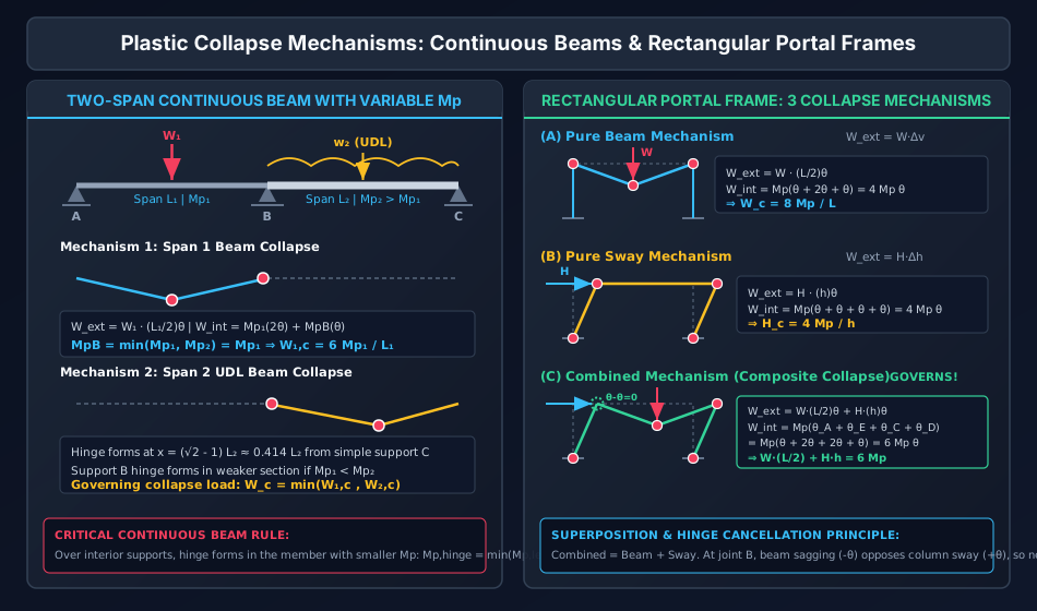
3.3 Two-Span Continuous Beam Formulations
Consider a two-span continuous beam with simple end supports at and , and a continuous interior support at :
- Span 1 (): Length , plastic moment capacity , point load at midspan.
- End is a simple support ().
- Support hinge capacity: .
- Virtual work for Span 1 collapse:
- If :
- Span 2 (): Length , plastic moment capacity , uniformly distributed load .
- End is a simple support ().
- Support hinge capacity: .
- As proven in Topic
STEEL-06-02, the interior plastic hinge forms at: - The collapse UDL for Span 2 is:
- The structure collapses when the applied load in either span reaches its respective critical limit:
4. Rectangular Portal Frames: Degrees of Freedom & Independent Mechanisms
4.1 Frame Topography and Potential Hinge Locations
Consider a standard single-bay rectangular portal frame with span and column height :
- Fixed-Base Frame: Bases and are rigidly fixed.
- Degree of static indeterminacy: .
- Possible plastic hinge locations ():
- Base of left column ()
- Left eaves/knee joint ()
- Under vertical concentrated load on beam ( at midspan)
- Right eaves/knee joint ()
- Base of right column ()
- Number of independent mechanisms:
- Pinned-Base Frame: Bases and are frictionless pins ().
- Degree of static indeterminacy: .
- Possible plastic hinge locations ():
- Left eaves/knee joint ()
- Under vertical load on beam ()
- Right eaves/knee joint ()
- Number of independent mechanisms:
4.2 Classification of Fundamental Independent Mechanisms
Every complex collapse mode of a single-bay rectangular frame is a linear combination of two elementary independent mechanisms:
- Beam Mechanism: Involves transverse deformation of the beam span while the columns remain vertical and undergo zero lateral displacement.
- Sway (Panel) Mechanism: Involves rigid lateral translation of the beam to the right or left with plastic hinges in the columns/joints, while the beam undergoes zero transverse flexure.
5. Fixed-Base & Pinned-Base Rectangular Frame Mechanisms
5.1 The Three Collapse Modes for a Fixed-Base Frame
Subjected to midspan vertical load and horizontal lateral surge at joint , with uniform plastic moment :
          W
          ↓
    B +---+---+ C  --> H
      |   E   |
      |       |
    A ╨       ╨ D
Mode A: Pure Beam Mechanism
- Active Hinges: , , (3 hinges).
- Virtual Rotations: , , .
- External Virtual Work: (Horizontal load does zero work since eaves do not translate horizontally).
- Internal Plastic Dissipation:
- Collapse Relation:
Mode B: Pure Sway Mechanism
- Active Hinges: , , , (4 hinges).
- Virtual Rotations: Left column rotates clockwise by (). Right column rotates clockwise by ().
- External Virtual Work: (Vertical load does zero work since beam remains horizontal without sagging).
- Internal Plastic Dissipation:
- Collapse Relation:
Mode C: Combined (Composite) Mechanism
- Superposition: Combining Beam Mechanism + Sway Mechanism.
- Hinge Kinematics at Joint :
- In Beam Mechanism: Beam slopes down to the right relative to column rotation is (joint closes).
- In Sway Mechanism: Column sways right by relative to beam rotation is (joint opens).
- Net rotation at joint :
- Hinge Kinematics at Joint :
- Beam slopes down to the left (). Column sways right ().
- Net rotation at joint :
- Active Hinges: , , , (4 hinges).
- External Virtual Work:
- Internal Plastic Dissipation:
- Collapse Relation:
====================================================================================
SUMMARY OF COLLAPSE EQUATIONS FOR FIXED-BASE FRAME (UNIFORM Mp)
------------------------------------------------------------------------------------
Mechanism               Active Hinges           Internal Work        External Work
------------------------------------------------------------------------------------
(1) Beam Mechanism      B, E, C                 4 Mp θ               W (L/2) θ
(2) Sway Mechanism      A, B, C, D              4 Mp θ               H h θ
(3) Combined Mechanism  A, E, C, D (B canceled) 6 Mp θ               [W (L/2) + H h] θ
====================================================================================
5.2 Unequal Member Capacities ( vs )
In practical design, column and beam sections are rarely identical:
- Let column plastic moment capacity be and beam capacity be .
- At knee joints and , the plastic hinge forms in the weaker member:
- If (strong beam - weak column, common in industrial sheds):
- Hinges at and form in the columns immediately below the rafter/beam connection.
- In Beam Mechanism: .
- In Sway Mechanism: .
- In Combined Mechanism: .
6. Pitched-Roof / Gable Portal Frames & Instantaneous Center of Rotation (ICR)
Industrial steel sheds commonly utilize pitched-roof gable frames with inclined rafters meeting at a central apex ridge (). Under combined gravity loads and wind suction/drag, rafter kinematics become two-dimensional.
6.1 Geometric Coordinates & Boundary Conditions
Consider a symmetric pinned-base gable frame:
- Left pinned base: .
- Left eave: .
- Apex ridge: , where is the roof rise ().
- Right eave: .
- Right pinned base: .
- Static indeterminacy: .
- Complete plastic collapse requires only plastic hinges (together with base pins and , creating a 4-bar kinematic mechanism).
6.2 Construction of the Instantaneous Center of Rotation (ICR)
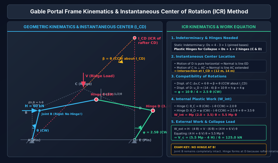
Under combined vertical load at the ridge and horizontal wind load at eave , the governing collapse mode is the Gable Mechanism where hinges form at:
- Ridge apex
- Leeward eave (inside the rafter or column)
- Joint remains completely rigid (no hinge forms at ).
Kinematic Derivation:
- Rigid Link : Since joints and remain rigid relative to rafter , members and form a single rigid body that rotates clockwise about fixed base pin by virtual angle .
- Displacement of eave :
- Displacement of ridge apex :
- Instantaneous Center of Rafter :
- Eave is pinned to column . Since column rotates about base pin , joint moves perpendicular to . Because is vertical, joint moves purely horizontally. The line of action normal to the displacement of is the vertical line through column :
- Apex is part of rigid body rotating about . The displacement vector of is perpendicular to chord . Therefore, the normal to the motion of is the line extended:
- The Instantaneous Center of rafter () is the geometric intersection of Line 1 and Line 2:
- Rotation Compatibility:
- Let counter-clockwise rotation of rafter about be .
- Vertical displacement of from :
- Equating from both sides:
- Horizontal displacement of eave :
- Since column rotates about base by clockwise angle :
6.3 Hinge Rotations & Internal Virtual Work
- At Ridge Apex : Member rotates clockwise by ; member rotates counter-clockwise by :
- At Leeward Eaves : Member rotates counter-clockwise by ; column rotates clockwise by :
- Total Internal Work Dissipated:
- External Work Done:
- Equating Virtual Work:
7. Minimum Weight Design Theorem & Optimum Plastic Moment Distribution
7.1 Foulkes's Theory of Minimum Weight Design
In economic structural design, the primary objective is to minimize total steel weight:
For standard rolled structural steel I-sections, empirical cross-sectional data demonstrates an almost linear relationship between steel cross-sectional area and plastic section modulus :
Therefore, the objective function for minimum structural steel frame weight simplifies to:
subject to the constraints that every potential collapse mechanism satisfies:
7.2 Heyman's Graphical Optimum Allocation
For a portal frame with beam plastic capacity (span ) and column plastic capacity (total column length ):
By plotting the linear mechanism inequalities on an versus coordinate system, the feasible region forms a convex polygon. The minimum-weight solution lies at a vertex (corner) of this polygon, representing a state where two independent collapse mechanisms govern simultaneously.
8. Visual Architecture & Structural Diagrams
8.1 Continuous Beam & Rectangular Portal Frame Mechanisms
The diagram below illustrates the plastic collapse mechanisms of continuous beams with variable and a fixed-base rectangular portal frame undergoing beam, sway, and combined collapse modes with hinge cancellation:
8.2 Gable Portal Frame Kinematics & Instantaneous Center Method
The diagram below details the 2D kinematics of a pitched-roof gable portal frame, including the geometric construction of the instantaneous center of rotation , rotation compatibility, and work formulations:
9. Solved Practical Design Examples
Problem 1: Fixed-Base Rectangular Portal Frame Analysis (Superposition & Governing Mechanism)
Problem Statement: A fixed-base single-bay rectangular portal frame has span and column height . The frame has a uniform plastic moment capacity throughout. It is subjected to a vertical concentrated service load at midspan of the beam, and a concurrent horizontal crane surge load applied at the left eaves joint .
- Determine the static indeterminacy and number of independent mechanisms .
- Calculate the collapse load for each potential collapse mechanism (Beam, Sway, Combined).
- Identify the governing collapse load and active plastic hinge locations.
- Perform a complete static equilibrium check to verify that everywhere.
Step-by-Step Mathematical Solution:
Step 1: Frame Kinematics
- Support conditions: Both column bases and are fully fixed.
- Potential hinge locations (): Base , Knee , Beam midspan , Knee , Base .
- Independent mechanisms:
Step 2: Collapse Load Formulations
- Beam Mechanism:
- Active hinges: , , .
- Sway Mechanism:
- Active hinges: , , , .
- Combined Mechanism:
- Active hinges: , , , (Hinge at cancels: ).
Step 3: Governing Collapse Load & Mechanism By the Upper Bound Theorem, the true collapse load is the minimum kinematically admissible load:
The Combined Mechanism strictly governs collapse. Plastic hinges form at , , , and .
Step 4: Static Verification () Let us verify the bending moment at joint where no hinge formed:
- For beam segment : Span , midspan load .
- Plastic hinges are active at () and ().
- Simple beam free bending moment at midspan:
- Relation between net moment and end support moments:
- Check yield condition:
Since equilibrium is satisfied, a valid mechanism is formed, and everywhere, by the Uniqueness Theorem is the exact true collapse load.
Problem 2: Pinned-Base Portal Frame with Unequal Member Capacities
Problem Statement: A pinned-base rectangular portal frame has span and height .
- Columns and have plastic moment capacity .
- Beam has plastic moment capacity .
- Column bases and are frictionless pins (). A constant horizontal surge load acts at joint . Determine the vertical collapse load applied at the center of beam .
Step-by-Step Mathematical Solution:
Step 1: Joint Plastic Capacity & Kinematics
- At knee joints and , since , plastic hinges will invariably form in the columns immediately below the eaves, with capacity:
- At beam midspan , the hinge forms in the beam: .
- Bases and are pins: .
- Degree of static indeterminacy: .
- Possible plastic hinge locations: (Column top at , Beam midspan , Column top at ).
- Independent mechanisms: .
Step 2: Mechanism Analysis
- Beam Mechanism:
- Active hinges: (in column), (in beam), (in column).
- Pure Sway Mechanism:
- Active hinges: (in column), (in column). Bases and are free pins.
- Note: The pure sway capacity of the frame is .
- Since applied , the frame is stable against pure sway.
- Combined Mechanism:
- Superposition cancels the hinge at : .
- Active hinges: Midspan (rotation ) and joint in column (rotation ).
Step 3: Conclusion The Combined Mechanism governs collapse. The maximum vertical service load the frame can sustain in the presence of lateral surge is (a reduction compared to the pure gravity beam capacity of ).
Problem 3: Gable Portal Frame via Instantaneous Center of Rotation (ICR)
Problem Statement: A symmetric pitch-roof gable portal frame has pinned bases at and .
- Span .
- Column height ( is at and is at ).
- Central apex ridge is at (roof rise ).
- The entire frame is fabricated from a uniform rolled steel section with . The frame is subjected to a vertical concentrated point load at the ridge apex and a concurrent horizontal wind load acting to the right at eaves joint . Using the Instantaneous Center of Rotation (ICR) method, determine the collapse value of the vertical ridge load .
Step-by-Step Mathematical Solution:
Step 1: Frame Kinematics & Degree of Indeterminacy
- Bases and are frictionless pins ().
- Static indeterminacy: .
- Total plastic hinges needed for complete single-degree-of-freedom mechanism:
- Under lateral load pushing right and vertical load pushing down, the windward joint remains completely rigid. Plastic hinges form at:
- Apex ridge
- Leeward eave
Step 2: Locating the Instantaneous Center of Rafter
- Member acts as a single rigid body rotating clockwise about fixed pin by angle .
- Apex displacement is perpendicular to vector . Therefore, the instantaneous center of rotation for rafter () must lie along line extended:
- Column rotates about fixed pin by clockwise angle .
- Eave moves perpendicular to vertical column (purely horizontally).
- Therefore, the instantaneous center must lie on the vertical line through :
- Finding coordinates of :
Step 3: Rotational Compatibility & Kinematic Displacements
- Let be the counter-clockwise rotation of rafter about .
- Displacements of ridge :
- From rigid body rotating clockwise by :
- From rafter rotating counter-clockwise by about :
- Equating vertical displacements:
- Displacements of eave :
- From rafter rotating counter-clockwise by about :
- Rotation of column about base :
- Since :
Step 4: Plastic Hinge Rotations & Internal Work
- At Ridge Hinge :
- Member rotates clockwise by .
- Member rotates counter-clockwise by .
- Net hinge rotation across :
- At Leeward Eaves Hinge :
- Member rotates counter-clockwise by .
- Column rotates clockwise by .
- Net hinge rotation across :
- Total Internal Plastic Work:
Step 5: External Virtual Work & Collapse Load
- Horizontal wind load at :
- Vertical ridge load at :
- Total external work:
- Equating internal and external work:
10. Critical Examination Traps, Pitfalls & Countermeasures
========================================================================================================================
EXAM TRAP IDENTIFIER                   FATAL ERROR TO AVOID                               CORRECT ENGINEERING PROCEDURE
========================================================================================================================
1. Pinned-Base Gable Frame Hinge Count  Assuming 3 or 4 plastic hinges are required       In a pinned-base gable frame,
                                       to form a collapse mechanism.                      Ds = 1. Therefore, only Ds + 1 = 2
                                                                                          plastic hinges are required!
------------------------------------------------------------------------------------------------------------------------
2. Knee Joint Hinge Cancellation       Double-counting plastic work at the windward       In combined mechanisms, the beam sagging
                                       eaves joint B during combined mechanism analysis.  rotation (-θ) and column sway rotation
                                                                                          (+θ) oppose each other: θ_net = 0.
                                                                                          No hinge forms at joint B!
------------------------------------------------------------------------------------------------------------------------
3. Unequal Section Support Capacity    Using the average or larger Mp at an interior      Plastic hinges form in the WEAKER cross-
                                       continuous beam support: Mp = (Mp1 + Mp2)/2.       section: Mp,support = min(Mp1, Mp2).
------------------------------------------------------------------------------------------------------------------------
4. ICR Sign in Gable Rafter Kinematics Confusing clockwise vs counter-clockwise          Rigid body ABC rotates CW; to satisfy
                                       rotation of rafter CD about I_CD, causing          compatibility, rafter CD rotates CCW.
                                       incorrect hinge rotation additions.                Hinge rotation at apex is θ_C = θ + β = 2θ.
------------------------------------------------------------------------------------------------------------------------
5. Interior Hinge Location under UDL   Assuming the interior span hinge under UDL         The interior hinge forms at exactly
                                       forms at midspan (0.50 L) in continuous spans.     x = (√2 - 1) L ≈ 0.4142 L from the
                                                                                          simple end support (0.5858 L from fixed).
========================================================================================================================
11. Multi-Exam Practical Assessment Questions
Question 1 (GATE CE - Advanced Kinematics)
A symmetric rectangular portal frame with fixed bases has span and column height . The plastic moment capacity is uniform . It carries a horizontal load at the left eaves and a vertical load at the beam center. The ratio of the collapse load to is:
- (A)
- (B)
- (C)
- (D)
Answer: (C) Detailed Solution:
- Beam mechanism: .
- Sway mechanism: .
- Combined mechanism:
- Governing collapse load: . Hence (B) is the exact value!
Question 2 (UPSC ESE Paper 1 - Architectural Concept)
In the plastic design of a continuous steel girder having adjacent spans of plastic moment capacities and where , the plastic hinge over the intermediate support:
- (A) Forms symmetrically across the support centerline with capacity
- (B) Forms in the span with capacity because larger sections attract higher moments
- (C) Forms in the span with capacity immediately adjacent to the support
- (D) Does not form because the stronger section prevents yielding
Answer: (C) Detailed Solution: As proven by limit analysis theorems, moment equilibrium dictates that the bending moment is continuous across the joint. The cross-section with lower capacity () reaches its plastic limit state first. The hinge forms inside the weaker span immediately adjacent to the intermediate support with capacity .
Question 3 (SSC JE - Direct Standard Formula)
For a propped cantilever beam of span and uniform plastic moment capacity subjected to a uniformly distributed load over the entire span, the collapse load is:
- (A)
- (B)
- (C)
- (D)
Answer: (B) Detailed Solution: For a propped cantilever under UDL, the interior plastic hinge forms at from the simple prop. The collapse load is .
Question 4 (State AE - Portal Frame Mechanisms)
In a single-bay rectangular portal frame with fixed bases subjected to vertical and horizontal loads, the number of possible plastic hinge locations is . The number of independent collapse mechanisms is:
- (A) 1
- (B) 2
- (C) 3
- (D) 4
Answer: (B) Detailed Solution: The static indeterminacy of a fixed-base single-bay portal frame is . The number of independent mechanisms is given by (the beam mechanism and the sway mechanism). The combined mechanism is obtained by superposing these two independent mechanisms.
Question 5 (RRB JE - Kinematics of Superposition)
When combining a beam mechanism and a sway mechanism in a rectangular portal frame to form a combined mechanism, what occurs at the windward knee joint?
- (A) The rotation doubles ()
- (B) Two independent hinges form simultaneously
- (C) The joint rotations cancel out (), so no hinge forms
- (D) The plastic moment capacity drops to zero
Answer: (C) Detailed Solution: In the beam mechanism, the beam sways down relative to the column, tending to close the angle. In the sway mechanism, the column tilts to the right, tending to open the angle by the exact same amount . Their superposition results in zero net angular discontinuity (). Hence, no plastic hinge forms at the windward eaves joint.
12. Comprehensive Standard Specifications & Academic References
- Bureau of Indian Standards (BIS):
- IS 800:2007: General Construction in Steel — Code of Practice (Third Revision). Section 8: Members Subjected to Combined Forces; Section 12: Plastic Design.
- American Institute of Steel Construction (AISC):
- AISC 360-16: Specification for Structural Steel Buildings. Appendix 1: Design by Inelastic Analysis.
- European Committee for Standardization (CEN):
- EN 1993-1-1:2005 (Eurocode 3): Design of Steel Structures — Part 1-1: General Rules and Rules for Buildings. Section 5.4: Methods of Analysis (Plastic Global Analysis).
- Foundational Academic Textbooks:
- Baker, J. F., & Heyman, J. (1969). Plastic Design of Frames: Volume 1, Fundamentals. Cambridge University Press.
- Neal, B. G. (1977). The Plastic Methods of Structural Analysis. Chapman and Hall.
- Subramanian, N. (2016). Design of Steel Structures (Limit State Method). Oxford University Press.
- Duggal, S. K. (2019). Limit State Design of Steel Structures. McGraw-Hill Education.