Bolted Connections (Bearing & Friction Grip HSFG Bolts — IS 800:2007)
In this chapter (4 topics)
On this page
- 1. Topic Title and Metadata
- 2. Prerequisites and Engineering Context
- 3. Fundamental Physical and Engineering Principles
- 3.1 Physical and Mechanical Properties of Structural Steel (IS 800:2007 Cl. 2.2.4)
- 3.2 Partial Safety Factors for Materials (γm) per IS 800:2007 Table 5
- 3.3 Classification and Mechanics of Bolted Fasteners
- 4. Rigorous Mathematical Derivations & Code Formulations
- 4.1 Standard Clearance Hole Diameters (d0) (IS 800:2007 Table 19)
- 4.2 Bolt Areas: Shank Area (Asb) vs Net Tensile Stress Area (Anb)
- 4.3 Design Capacity of Bearing-Type Bolts (IS 800:2007 Cl. 10.3)
- 4.4 Design Capacity of HSFG Friction-Grip Bolts (IS 800:2007 Cl. 10.4)
- 4.5 Plate Tensile Rupture & Joint Efficiency
- 5. Detailing Rules and Codal Mandates (IS 800:2007 Cl. 10.2)
- 6. SVG Diagrams and Visual Explanations
- 6.1 Bolted Connection Detailing Geometry & The Six Failure Modes
- 6.2 Bearing Bolts vs HSFG Friction Grip Fasteners & Interaction Curves
- 7. Solved Numerical Examples
- 7.1 Example 1: Design of a Bearing-Type Bolted Lap Joint under Tension
- 7.2 Example 2: HSFG (Slip-Critical) Double Cover Butt Joint
- 7.3 Example 3: Verification of Bolted Connection under Combined Shear and Tension
- 8. Common Pitfalls, Misconceptions, and Examination Traps
- 9. Comparative Analysis and Summary Tables
- 9.1 Bearing-Type Bolts vs High-Strength Friction Grip (HSFG) Bolts
- 10. Exam-Specific Focus and Formula Cheat Sheet
- 10.1 Must-Remember Formulas for Quick Objective Calculations
- 11. Practice Problems and Self-Assessment with Numerical Answers
- 12. Standard References and Further Reading
1. Topic Title and Metadata
| Attribute | Specification |
|---|---|
| Topic ID | STEEL-01-01 |
| Module / Subject | Subject 06: Design of Steel Structures (IS 800:2007) |
| Chapter | Chapter 01: Structural Steel Fundamentals & Connection Design |
| Topic Title | Bolted Connections (Bearing & Friction Grip HSFG Bolts, Shear, Bearing & Tensile Capacities) |
| Applicable Standards | IS 800:2007 (General Construction in Steel — Code of Practice), IS 1367, IS 3757, IS 4000, AISC 360-16, Eurocode 3 (EN 1993-1-8) |
| Target Examinations | GATE CE, UPSC ESE (Paper-I), SSC JE, State PSC AE/JE, RRB JE |
| Primary Authorship | Civil Engineering Autonomous Master Repository |
| Verification Gate | Level 1 through Level 7 (Mathematical Recalculation, Codal Compliance, SVG Validation) |
2. Prerequisites and Engineering Context
To master the limit state design of structural steel bolted fasteners, the student and structural engineer must be proficient in:
- Mechanics of Materials (
SOM-01-01,SOM-05-01): Direct shear stress across cross-sections, contact/bearing stresses on curved cylindrical boundaries, and net tensile stress concentration. - Ductile vs Brittle Plasticity (
SOM-01-02): Yield plateau, strain hardening, ultimate tensile strength (), and elongation percentage. - Limit State Design Philosophy (
RCC-01-01): Partial safety factors for materials () and loads (), characteristic loads, and limit states of strength vs serviceability.
Structural steel connections are the critical links that transfer internal axial forces, shear forces, and bending moments between individual members (beams, columns, trusses, and bracing). Statistically, structural collapses in steel buildings and bridges initiate at faulty or under-designed connections rather than within member bodies. Modern structural practice predominantly utilizes bolted connections (for fast, weather-independent site erection) and welded connections (for rigid factory prefabrication).
3. Fundamental Physical and Engineering Principles
3.1 Physical and Mechanical Properties of Structural Steel (IS 800:2007 Cl. 2.2.4)
For all standard structural steels conforming to IS 2062:
- Mass Density (): ().
- Modulus of Elasticity (): ().
- Poisson's Ratio ( or ):
- In elastic range:
- In plastic range: (incompressible yielding)
- Shear Modulus ():
- Coefficient of Linear Thermal Expansion (): .
3.2 Partial Safety Factors for Materials () per IS 800:2007 Table 5
In limit state design, nominal material resistances are divided by partial safety factors:
| Structural Condition | Governing Mechanism | Partial Safety Factor () |
|---|---|---|
| Member Resistance | Yielding of gross cross-section | |
| Member Resistance | Ultimate tensile rupture of net section | |
| Member Resistance | Buckling of compression members | |
| Bolts (Bearing Type) | Shear, bearing, and tension resistance | |
| Bolts (HSFG Friction) | Slip resistance at serviceability limit state | |
| Bolts (HSFG Friction) | Slip resistance at ultimate limit state | |
| Welds | Shop fabrication | |
| Welds | Field / Site fabrication |
3.3 Classification and Mechanics of Bolted Fasteners
Bolts used in structural engineering are categorized into three broad classes:
1. Black Bolts (Ordinary / Unfinished Bolts)
- Manufactured from mild steel hexagonal rods conforming to IS 1363 (Property Class 4.6, 5.6).
- Property Class Notation (e.g., Class 4.6):
- First digit = Nominal ultimate tensile strength: .
- Second digit = Nominal yield strength: .
- Installed in standard clearance holes ().
- Load Transfer: As load is applied, the connected plates first slip past each other until the bolt hole edge physically bears against the cylindrical bolt shank. Load is transferred through bearing pressure on the hole wall and transverse shear across the bolt shank.
2. Turned and Fitted Bolts
- Machine-turned hexagonal bolts fitted into reamed, close-tolerance holes with zero clearance (). Eliminates initial joint slip but involves high manufacturing costs.
3. High-Strength Friction Grip (HSFG) Bolts
- Manufactured from quenched and tempered medium carbon or alloy steel conforming to IS 3757 (Property Class 8.8, 10.9).
- Class 8.8: .
- Class 10.9: .
- Tightened using calibrated torque wrenches or load-indicating washers to a precise initial tension (proof load ).
- Load Transfer: The massive clamping force clamps the connected plates tightly together. Applied shear forces are resisted purely by interfacial friction between the plate surfaces.
- Advantages:
- No joint slip under service loads (rigid joint behavior).
- Excellent fatigue and dynamic impact resistance (no stress concentration at hole bearing).
- Bolts are subjected to static tension; alternating external shear does not induce shear stress reversals in the shank.
4. Rigorous Mathematical Derivations & Code Formulations
4.1 Standard Clearance Hole Diameters () (IS 800:2007 Table 19)
To permit easy alignment and insertion during erection, holes drilled or punched in steel plates are slightly larger than the nominal bolt diameter :
| Nominal Bolt Diameter () | Standard Clearance () | Standard Hole Diameter () |
|---|---|---|
Example: A nominal diameter bolt requires a standard hole diameter of .
4.2 Bolt Areas: Shank Area () vs Net Tensile Stress Area ()
A standard bolt consists of an unthreaded cylindrical shank and a threaded portion:
- Nominal Shank Area (): Gross cross-sectional area of unthreaded shank:
- Net Tensile Stress Area at Threads (): Area at the root of the thread. Per IS 800:2007 Cl. 10.3.3:
4.3 Design Capacity of Bearing-Type Bolts (IS 800:2007 Cl. 10.3)
4.3.1 Shear Capacity of Bolt ()
Under transverse shear, the bolt can fail by shearing across one or more cross-sections. The design shear strength of a bolt is:
where:
- = Ultimate tensile strength of the bolt material ( for Class 4.6).
- = Shear yield strength per von Mises failure criterion.
- = Partial safety factor for bolt material (Table 5).
- = Number of shear planes intercepting the threaded portion of the bolt shank.
- = Number of shear planes intercepting the unthreaded cylindrical shank.
- = Net tensile stress area at threads ().
- = Nominal shank area ().
- Conservative Rule: If the location of the thread run-out is not verified, assume all shear planes pass through the threads ().
- For single shear lap joint: .
- For double shear butt joint: .
4.3.2 Bearing Capacity of Bolt on Connected Plate ()
Bearing failure occurs when the cylindrical surface of the bolt shank crushes against the hole wall in the plate, causing hole elongation or shank indentation. The design bearing strength of a bolt is governed by:
where:
- = Nominal diameter of bolt.
- = Aggregate thickness of connected plates experiencing bearing in the same direction:
- For a lap joint: .
- For a double cover butt joint: .
- = Smaller of the ultimate tensile strength of the plate () and the bolt ().
- .
- = Bearing factor accounting for end distance, pitch, and relative material strengths:
where:
- = End distance (measured from center of outer bolt hole to plate edge parallel to load).
- = Pitch (center-to-center spacing of adjacent bolts along the direction of load).
- = Standard clearance hole diameter.
Physical Significance of Terms:
- : Prevents end tear-out/splitting of the plate ahead of the bolt.
- : Prevents shear splitting between adjacent bolt holes.
- : Protects against bolt shank crushing when plate steel is stronger than bolt steel.
- : Upper limit representing full triaxial bearing plasticization.
4.3.3 Tensile Capacity of Bolt () (IS 800:2007 Cl. 10.3.5)
When a bolt is subjected to direct axial tension (e.g., hanger connections, bracket tension):
For standard Class 4.6 bolts with :
4.3.4 Bolt Value () & Number of Bolts Required
The design capacity of a single fastener in a shear connection is termed the Bolt Value ():
For a connection transmitting a total factored shear load :
(Always rounded up to the next whole integer).
4.3.5 Combined Shear and Tension Interaction (IS 800:2007 Cl. 10.3.6)
When a bearing bolt is subjected to simultaneous factored shear and factored tension :
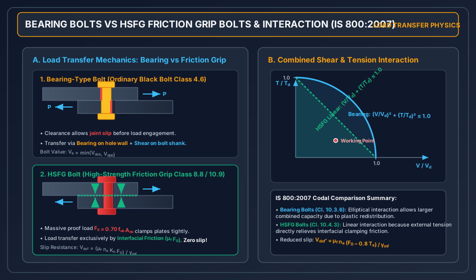
This elliptical interaction profile accounts for the multi-axial von Mises yield criterion and plastic redistributive capacity of ductile mild steel bolts.
4.4 Design Capacity of HSFG Friction-Grip Bolts (IS 800:2007 Cl. 10.4)
4.4.1 Minimum Bolt Tension / Proof Load ()
HSFG bolts are pre-tensioned to a minimum clamping force specified as of their nominal tensile capacity:
4.4.2 Design Slip Resistance () (Cl. 10.4.3)
The design resistance to relative slip between connected plies is:
where:
- = Slip factor (coefficient of friction at interface):
- Normal clean mill scale steel surface: .
- Blast-cleaned / grit-blasted surface: .
- Blast-cleaned with spray metal coating (zinc/aluminum): .
- = Number of effective friction slip interfaces:
- Lap joint: .
- Double cover butt joint: .
- = Hole clearance factor:
- Standard clearance holes: .
- Oversized or short slotted holes: .
- Long slotted holes: .
- = Partial safety factor for slip resistance:
- Serviceability Limit State: (joint must not slip under normal working loads).
- Ultimate Limit State: (slip constitutes catastrophic limit state).
4.4.3 Combined Shear and Tension for HSFG Bolts (Cl. 10.4.3.4)
When an external tension force acts on an HSFG connection, it pulls the plates apart, directly reducing the normal clamping contact pressure :
Equivalently, the effective slip resistance is reduced to:
where is a reduction factor accounting for prying and elastic deformation.
4.5 Plate Tensile Rupture & Joint Efficiency
4.5.1 Net Effective Plate Area ()
Presence of bolt holes reduces the cross-sectional area of connected plates:
- For a straight chain of bolt holes across plate width and thickness :
- For staggered bolt patterns with gauge and staggered pitch :
4.5.2 Design Tensile Strength of Net Section () (Cl. 6.3.1)
where for Fe 410 steel and .
4.5.3 Gross Section Yielding Strength of Plate () (Cl. 6.2)
where .
4.5.4 Joint Efficiency ()
where:
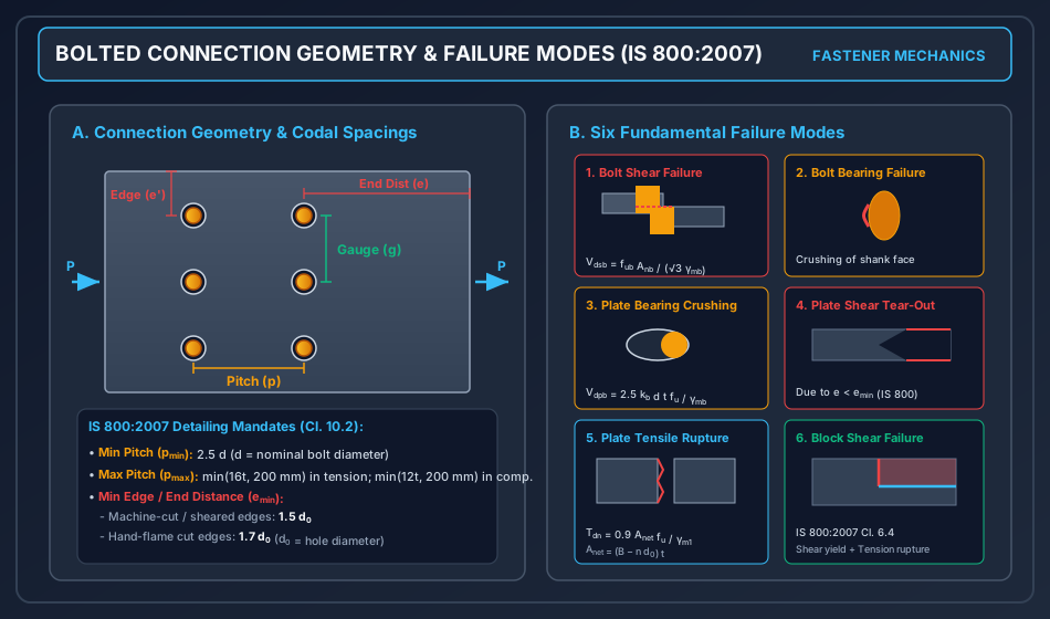
5. Detailing Rules and Codal Mandates (IS 800:2007 Cl. 10.2)
        |<--- e --->|<-------- p -------->|<--- e --->|
        +-----------+---------------------+-----------+  ---
        |           |                     |           |   ^
        |     O     |          O          |     O     |   | e' (Edge distance)
        |           |                     |           |   v
        |           |                     |           |  ---
        |           |                     |           |   ^
        |           |                     |           |   | g (Gauge)
        |           |                     |           |   v
        |     O     |          O          |     O     |  ---
        |           |                     |           |   ^
        |           |                     |           |   | e' (Edge distance)
        +-----------+---------------------+-----------+  ---
        |=============================================> Load Direction
- Minimum Pitch (): Prevents overlapping of localized plastic bearing zones in adjacent holes and provides physical clearance for tightening sockets.
- Maximum Pitch ():
- For members in tension:
- For members in compression: (prevents local buckling of plies between fasteners).
- If bolts are staggered and gauge , the above limits may be increased by (i.e., for tension, for compression).
- For tacking fasteners (not carrying calculated load): for unexposed, or if exposed to weather.
- Minimum Edge and End Distances ():
- For sheared, cropped, or hand-flame cut edges:
- For rolled, machine-flame cut, sawn, or planed edges:
- Maximum Edge Distance ():
- In ordinary non-corrosive environments: (where ).
- In corrosive / exposed environments: .
6. SVG Diagrams and Visual Explanations
6.1 Bolted Connection Detailing Geometry & The Six Failure Modes
The following original diagram details joint geometry parameters (pitch , gauge , end distance , edge distance ) and illustrates the six fundamental structural failure modes encountered in bolted connections.
6.2 Bearing Bolts vs HSFG Friction Grip Fasteners & Interaction Curves
The following diagram contrasts the physical load transfer mechanisms of bearing bolts (hole wall contact) versus HSFG friction grip bolts (clamping pre-tension ), and compares their interaction response curves under combined shear and tension.
7. Solved Numerical Examples
7.1 Example 1: Design of a Bearing-Type Bolted Lap Joint under Tension
Problem Statement:
Two plates of width , thickness and of Fe 410 grade steel () are connected by a lap joint to transmit a factored tensile load . The bolts used are Class 4.6 with nominal diameter .
- Determine the design shear capacity and bearing capacity of a single bolt.
- Compute the Bolt Value and find the required number of bolts.
- Check the net tensile capacity of the plate across the critical bolt line and determine the joint efficiency .
Step-by-Step Solution:
-
Step 1: Bolt Geometry & Section Properties
- Nominal diameter .
- Standard hole diameter (for bolt, add ):
- Nominal shank area:
- Net tensile area at threads (IS 800:2007 Cl. 10.3.3):
- For Class 4.6 bolts: .
-
Step 2: Design Shear Capacity of Bolt ()
- Single shear plane passing through threads ():
-
Step 3: Design Bearing Capacity of Bolt ()
- Effective bearing plate thickness: .
- Provide standard detailing distances:
- Evaluate :
- Nominal bearing strength:
- Design bearing strength:
-
Step 4: Bolt Value & Required Number of Bolts
(Arranged in 2 rows of 3 bolts each).
-
Step 5: Net Section Tensile Rupture Check ()
- Across the critical end bolt line (2 bolt holes across width ):
-
Step 6: Joint Efficiency ()
- Gross plate tensile strength:
- Total joint shear strength .
- Governing joint strength .
7.2 Example 2: HSFG (Slip-Critical) Double Cover Butt Joint
Problem Statement:
A double cover butt joint connects two main plates of width and thickness carrying a working axial tensile load (factored load ). Two cover plates of thickness each are provided. HSFG bolts of Class 8.8 with nominal diameter are to be used in standard clearance holes. The slip factor of the interface is .
- Calculate the minimum proof load (clamping force ) per bolt.
- Determine the design slip resistance per bolt under both serviceability () and ultimate limit state ().
- Determine the required number of HSFG bolts on each side of the joint.
Step-by-Step Solution:
-
Step 1: Fastener Geometric Properties
- Bolt diameter , standard hole .
- Nominal shank area: .
- Net tensile area at threads:
- For Class 8.8 HSFG bolts: .
-
Step 2: Minimum Proof Load ()
- Minimum clamping force per bolt (IS 800:2007 Cl. 10.4.3.1):
-
Step 3: Design Slip Resistance per Bolt ()
- Double cover butt joint provides two effective friction interfaces: .
- Standard clearance holes: .
- Nominal slip resistance:
- At Serviceability Limit State ():
- At Ultimate Limit State ():
-
Step 4: Number of HSFG Bolts Required per Side
- Checking against ultimate factored load :
- Checking against working service load :
- The design is governed by the ultimate limit state: Provide 6 HSFG bolts on each side of the splice (total 12 bolts in joint).
7.3 Example 3: Verification of Bolted Connection under Combined Shear and Tension
Problem Statement:
A column-bracket connection transmits a factored shear force and a factored tensile force . The joint consists of 4 bolts of Class 4.6, connecting a thick bracket plate (). Spacing: pitch , end distance .
- Compute the design shear capacity (), design bearing capacity (), and design tensile capacity () per bolt.
- Verify the structural safety of the fasteners using the IS 800:2007 interaction criterion.
Step-by-Step Solution:
-
Step 1: Applied Forces per Fastener
-
Step 2: Bolt Capacities
- Bolt diameter .
- Shear Capacity ():
- Bearing Capacity ():
- Tensile Capacity (): (Tensile yield check: ).
-
Step 3: Interaction Criterion (IS 800:2007 Cl. 10.3.6)
8. Common Pitfalls, Misconceptions, and Examination Traps
- Confusing Nominal Shank Area with Net Tensile Area:
- Trap: Using for shear calculation when threads are in the shear plane.
- Reality: Standard practice assumes threads cross the shear plane unless specifically detailed otherwise. Always use for and .
- Double Shear Bearing Thickness Pitfall:
- Trap: In a double cover butt joint, taking .
- Reality: Connected plates push in opposite directions. The critical bearing thickness is .
- Misinterpreting Calculation:
- Trap: Omitting the factor in the pitch term or dividing by instead of .
- Reality: Hole diameter must be used in the denominator, not nominal bolt diameter .
- Interaction Formula Exponents:
- Trap: Applying linear interaction to ordinary bearing bolts.
- Reality: Bearing bolts follow an elliptical interaction . HSFG friction bolts follow a linear interaction because tension directly relieves the clamping friction.
- Pitch vs Gauge Orientation:
- Trap: Swapping pitch and gauge.
- Reality: Pitch () is measured parallel to the line of action of load. Gauge () is measured perpendicular to the line of action of load.
9. Comparative Analysis and Summary Tables
9.1 Bearing-Type Bolts vs High-Strength Friction Grip (HSFG) Bolts
| Characteristic | Bearing-Type Bolts (Class 4.6) | HSFG Bolts (Class 8.8 / 10.9) |
|---|---|---|
| Material | Low carbon / Mild steel | Medium carbon / Quenched & tempered alloy |
| Load Transfer Mechanism | Bearing on hole wall + Shear across shank | Interfacial friction between clamped plates |
| Hole Clearance Contact | Shank bears directly against hole edge | Shank does NOT touch hole edge under service |
| Initial Tightening | Snug-tight / normal wrenching | Calibrated proof tension |
| Joint Slip | Slips into bearing before taking full load | Zero slip under serviceability limit state |
| Fatigue Performance | Poor (stress concentrations at bearing face) | Superior (no stress reversal on shank) |
| Combined V & T Interaction | Elliptical: | Linear: |
| Typical Use | Static roofs, secondary trusses, purlins | Bridges, cranes, dynamic towers, seismic frames |
10. Exam-Specific Focus and Formula Cheat Sheet
10.1 Must-Remember Formulas for Quick Objective Calculations
11. Practice Problems and Self-Assessment with Numerical Answers
-
Practice Problem 1: Calculate the bolt value of an M20 bolt of Class 4.6 in single shear connecting two thick plates of Fe 410 steel. Given: .
Answer: . . . . Bolt Value . -
Practice Problem 2: An M24 HSFG bolt of Class 8.8 connects two plates in a lap joint (). The surfaces are blast cleaned (). Standard clearance holes are used (). Compute the design slip resistance at serviceability ().
Answer: . Proof load . Nominal slip . . -
Practice Problem 3: A plate of size (Fe 410, ) is connected to a gusset plate using 3 bolts of diameter in a single line along the load direction (1 bolt per cross-section). Find the design tensile rupture strength of the plate.
Answer: Critical section has 1 hole (). . .
12. Standard References and Further Reading
- IS 800:2007: General Construction in Steel — Code of Practice (Third Revision), Bureau of Indian Standards, New Delhi. (Section 10: Connections).
- Subramanian, N.: Design of Steel Structures, Oxford University Press, New Delhi. (Chapter 5: Bolted Connections).
- Duggal, S.K.: Limit State Design of Steel Structures, 3rd Edition, McGraw Hill Education.
- Bhavikatti, S.S.: Design of Steel Structures (By Limit State Method as Per IS: 800-2007), I.K. International Publishing House.
- IS 3757:1985: High Strength Structural Bolts, Bureau of Indian Standards.