Shear Capacity, High Shear Interaction & Web Post-Buckling
In this chapter (4 topics)
On this page
- 1. Topic Overview & Engineering Significance
- 2. Code Provisions & Theoretical Derivations
- 2.1 Plastic Shear Capacity of Webs (IS 800:2007 Cl. 8.4.1)
- 2.2 Threshold for Web Shear Buckling (IS 800:2007 Cl. 8.4.2)
- 2.3 Post-Buckling Shear Resistance: Simple Post-Critical Method (IS 800:2007 Cl. 8.4.2.2)
- 2.4 Combined Bending and Shear: Low vs High Shear (IS 800:2007 Cl. 8.2.1.2 & 8.2.1.3)
- 3. Visual Diagrams & Structural Behavior
- Figure 1: Web Shear Stress Distribution & Slenderness Thresholds
- Figure 2: High Shear Moment-Shear (M-V) Interaction Domain & Stress Decomposition
- 4. Mathematical Formulations & Design Procedures
- 5. Solved Numerical Examples
- Problem 1: Laterally Supported Beam under High Shear Interaction
- Problem 2: Comparative Evaluation of Web Shear Buckling (Rolled vs Welded Web)
- Problem 3: Continuous M-V Interaction Curve Mapping
- 6. Comparative Engineering Analysis
- 7. Design Pitfalls & Practical Field Considerations
- 8. Summary of Critical Formulae
- 9. Exam Traps & Tricks
- 10. Recommended Indian Standard Codes & Textbooks
- 11. Practice Problems with Answer Keys
- Problem 1 (GATE CE Objective)
- Problem 2 (UPSC ESE Objective)
- Problem 3 (GATE CE Numerical Answer Type)
- 12. Cross-Topic Linkages & Forward References
1. Topic Overview & Engineering Significance
In structural steel flexural members, bending moment and shear force act simultaneously across the span. While flexure generates longitudinal normal stresses () concentrated predominantly in the flanges, transverse shear force () generates shear stresses () carried almost entirely by the beam web ().
Under the Limit State Method of IS 800:2007, the design of beams in shear is governed by two fundamental physical thresholds:
- Web Slenderness & Shear Buckling Threshold (): If the web is stocky (), it can attain full plastic shear yielding () across its entire area without buckling. Conversely, if , elastic or inelastic out-of-plane shear buckling occurs prior to full cross-sectional shear plastification, necessitating post-buckling evaluation or transverse stiffeners.
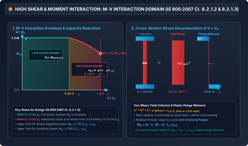
- High Shear Interaction Threshold (): Under low shear conditions (), transverse shear does not impair the plastic moment capacity of the section (). However, when shear force exceeds of the design plastic shear capacity (, termed High Shear), the bi-axial yield criterion of von Mises dictates that yield in shear significantly reduces the capacity of the web to resist longitudinal flexural normal stresses. Consequently, the design bending resistance degrades parabolically from down to the plastic moment capacity of the flanges alone ().
Mastery of shear design, high shear moment-shear () interaction, and web buckling criteria is critical for designing heavily loaded transfer girders, continuous bridge beams near internal supports, cantilever beams at column junctions, and built-up plate girders.
2. Code Provisions & Theoretical Derivations
2.1 Plastic Shear Capacity of Webs (IS 800:2007 Cl. 8.4.1)
Under pure transverse shear, yielding of structural steel is governed by the von Mises (Distortion Energy) Yield Criterion. In a state of pure shear stress , the equivalent von Mises stress is:
Applying the partial safety factor for material yield , the design plastic shear resistance is:
Where:
- is the effective shear area of the cross-section.
- is the yield strength of the web (typically for E250 steel).
- is the partial safety factor against material yielding (Table 5).
Shear Area () Provisions (IS 800:2007 Cl. 8.4.1.1):
- Rolled I and H Sections (Major-Axis Bending): Where is the overall depth of the section, and is the web thickness. (Notice that rolled sections credit root fillets and web portions within flange thickness).
- Welded I and H Sections (Major-Axis Bending): Where is the clear depth of the web between flanges ().
- Rolled Channels (Shear parallel to web):
- Built-up Channels, Angles, and Rectangular Hollow Sections: Refer to IS 800:2007 Cl. 8.4.1.1 for explicit component area formulations.
- Circular Hollow Sections (CHS):
2.2 Threshold for Web Shear Buckling (IS 800:2007 Cl. 8.4.2)
A flat web plate subjected to pure in-plane shear develops principal tensile and compressive stresses at to the longitudinal axis:
The diagonal compressive stress () acts as an internal thrust along the web diagonal. If the web is slender, this diagonal compression causes out-of-plane lateral buckling before the material reaches plastic shear yield.
According to IS 800:2007 Cl. 8.4.2.1:
- Unstiffened Webs: Web shear buckling shall be verified when:
Where . For standard Fe 410 steel (), .
- When : The web is classified as stocky. It attains its full plastic shear capacity without buckling ().
- When : Web shear buckling governs. The nominal shear strength must be computed using either the Simple Post-Critical Method or the Tension Field Method.
2.3 Post-Buckling Shear Resistance: Simple Post-Critical Method (IS 800:2007 Cl. 8.4.2.2)
For unstiffened or stiffened webs where , the nominal shear resistance is determined by the shear buckling stress :
The shear buckling stress depends on the non-dimensional web slenderness parameter :
Where the elastic critical shear buckling stress of the plate panel is:
- (Modulus of elasticity)
- (Poisson's ratio), so .
- is the web shear buckling coefficient:
- If :
- If :
- For an unstiffened web (no intermediate stiffeners, ): .
Evaluation of Design Shear Buckling Stress :
- Stocky Web (): (Full plastic shear yield; no buckling reduction).
- Inelastic Transition ():
- Slender Elastic Buckling (): (Note: For , the buckling stress matches classical Euler plate shear buckling exactly).
2.4 Combined Bending and Shear: Low vs High Shear (IS 800:2007 Cl. 8.2.1.2 & 8.2.1.3)
When bending moment and factored shear force act concurrently on a beam cross-section:
Case A: Low Shear Regime ()
Under low shear, plastic stress redistribution permits the flanges and un-yielded portions of the web to develop full plastic bending capacity without interference from shear stress.
Case B: High Shear Regime ()
When the applied shear exceeds of the plastic shear capacity (), a large portion of the web is required to carry shear, and the von Mises yield criterion restricts the longitudinal normal stress that the web can sustain:
As , . Thus, the web becomes virtually incapable of resisting bending moment.
To account for this degradation smoothly, IS 800:2007 Cl. 8.2.1.3 specifies the reduced design bending strength :
For Class 1 (Plastic) and Class 2 (Compact) Sections:
Where:
- is the design bending strength under low shear (, with for Class 1 & 2).
- is the non-dimensional shear interaction parameter:
- is the design plastic resistance of the flanges alone (disregarding the web completely): (Where is flange width, is flange thickness, and is the center-to-center distance between flanges).
Boundary Behavior of the Interaction Parameter :
- At : (smooth continuous tangency with low shear plateau).
- At : . Substituting into the equation: The bending capacity reduces strictly to the flange-only plastic capacity!
For Class 3 (Semi-Compact) Sections:
Where is the elastic section modulus of the reduced cross-section, determined by discounting the shear-stressed web area.
3. Visual Diagrams & Structural Behavior
Figure 1: Web Shear Stress Distribution & Slenderness Thresholds
The diagram below contrasts the classical parabolic elastic shear distribution with the Limit State plastic shear distribution and illustrates the slenderness regimes for web buckling.
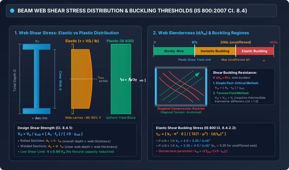
Figure 2: High Shear Moment-Shear () Interaction Domain & Stress Decomposition
The following figure illustrates the interaction boundary curve under IS 800:2007, showing the low-shear plateau, the parabolic capacity reduction zone, and the physical stress decomposition between web and flanges.
4. Mathematical Formulations & Design Procedures
+---------------------------------------------------------------------------------+
|                   COMPLETE IS 800:2007 SHEAR DESIGN ALGORITHM                   |
+---------------------------------------------------------------------------------+
                                         |
                                         v
                         [ Step 1: Factored Design Actions ]
                         Applied Shear: V ; Applied Moment: M
                                         |
                                         v
                     [ Step 2: Determine Effective Shear Area Av ]
                     Rolled I-section:  Av = h * tw
                     Welded I-section:  Av = d * tw
                                         |
                                         v
                     [ Step 3: Check Web Buckling Slenderness ]
                                   d / tw <= 67 epsilon ?
                                  /                      \
                             (YES)                        (NO)
                              /                              \
         [ Stocky Web: No Buckling ]            [ Slender Web: Buckling Governs ]
         Vd = [ Av * fy ] / [ sqrt(3) * gm0 ]   Compute kv (Cl. 8.4.2.2)
                                                Compute tau_cr and lambda_w
                                                Determine tau_b -> Vcr
                                         |
                                         v
                         [ Step 4: Evaluate Applied Shear ]
                                   V <= Vd (or Vcr) ?
                                  /                  \
                             (YES)                    (NO)
                              /                          \
                     Proceed to Step 5              FAIL: Increase tw or
                                                    provide stiffeners
                                         |
                                         v
                       [ Step 5: Check High Shear Threshold ]
                                      V <= 0.60 Vd ?
                                     /              \
                                (YES)                (NO)
                                 /                      \
                     [ Low Shear Regime ]         [ High Shear Regime ]
                     Mdv = Md = Zp * fy / gm0     Compute beta = (2V/Vd - 1)^2
                                                  Compute Mfd = bf*tf*(D-tf)*fy/gm0
                                                  Mdv = Md - beta * (Md - Mfd)
                                         |
                                         v
                         [ Step 6: Apply Upper Bound Limit ]
                         Simply Supported:  Mdv <= 1.20 Ze * fy / gm0
                         Cantilever:        Mdv <= 1.50 Ze * fy / gm0
                                         |
                                         v
                       [ Step 7: Final Flexural Adequacy ]
                                      M <= Mdv ?
                                     /          \
                                (YES)            (NO)
                                 /                  \
                           SAFE & VERIFIED      RE-SELECT SECTION
5. Solved Numerical Examples
Problem 1: Laterally Supported Beam under High Shear Interaction
Statement:
A simply supported laterally supported steel beam fabricated from ISMB 500 @ 86.9 kg/m is subjected to a factored bending moment and a concurrent factored shear force at a critical section. Steel grade is E250 (, ).
Section properties for ISMB 500:
- Overall depth
- Flange width
- Flange thickness
- Web thickness
- Root radius
- Plastic section modulus
- Elastic section modulus
Determine whether the section is adequate under combined flexure and shear in accordance with IS 800:2007.
Solution:
Step 1: Section Classification (Table 2)
- Outstand of flange
- Clear web depth
Hence, the cross-section is Class 1 (Plastic) with .
Step 2: Web Slenderness & Buckling Check (Cl. 8.4.2)
The web is stocky; web shear buckling will not occur prior to full plastic shear yielding.
Step 3: Design Plastic Shear Resistance () For rolled I-sections, effective shear area is :
Check shear strength adequacy:
Step 4: Check for High Shear Regime
Since applied shear (), the beam is in the High Shear Regime! Moment capacity must be reduced.
Step 5: Full Plastic Moment Capacity ()
Upper limit check (simply supported):
Since , the unreduced moment capacity is .
Step 6: Flange Plastic Moment Resistance () Disregarding the web completely, the plastic modulus of the two flanges is:
Step 7: Interaction Parameter and Reduced Moment Capacity
The reduced design bending strength is:
Upper bound check:
Step 8: Final Flexural Adequacy Verification
Conclusion: The section ISMB 500 is SAFE and structurally adequate under combined high shear and bending moment.
Problem 2: Comparative Evaluation of Web Shear Buckling (Rolled vs Welded Web)
Statement:
Compare the shear resistance of the following two steel sections fabricated from E250 steel (, , , ):
- Rolled Section A (ISMB 600): , , clear depth .
- Welded Plate Girder Web B: Clear depth , web thickness , stiffened with intermediate transverse stiffeners at spacing ().
Evaluate whether shear buckling occurs in each section and calculate their design shear capacities.
Solution:
Section A: Rolled ISMB 600
- Slenderness ratio:
- Buckling limit: .
- Effective shear area for rolled section: .
- Plastic shear capacity:
Section B: Welded Plate Girder Web
-
Slenderness ratio:
-
Buckling limit check:
-
Effective shear area for welded section: .
-
Theoretical plastic shear limit (if buckling were suppressed):
-
Evaluation by Simple Post-Critical Method (Cl. 8.4.2.2): With aspect ratio :
Elastic critical shear stress:
-
Non-dimensional web slenderness :
-
Shear buckling stress : Since , the web is in the elastic buckling domain:
-
Design shear buckling strength :
Summary Comparison:
- For the plate girder web, shear buckling reduces the shear capacity from to —a massive loss in capacity due to elastic out-of-plane web buckling!
Problem 3: Continuous Interaction Curve Mapping
Statement:
For an ISMB 450 @ 72.4 kg/m beam (, , , , , , , ), map the design moment capacity across the entire shear spectrum .
Solution:
Step 1: Section Capacities
Flange plastic moment :
Step 2: Parametric Spectrum Calculation
| Ratio | Shear (kN) | Regime | (kN-m) | % of | |
|---|---|---|---|---|---|
| 0.60 | 333.03 | Low Shear Boundary | 348.50 | 100.0% | |
| 0.70 | 388.54 | High Shear | 95.8% | ||
| 0.80 | 444.04 | High Shear | 90.5% | ||
| 0.90 | 499.55 | High Shear | 83.1% | ||
| 1.00 | 555.05 | Plastic Shear Limit | 73.6% |
Engineering Insight: Notice that between and , the moment capacity drops by , landing exactly on the flange plastic moment .
6. Comparative Engineering Analysis
| Design Parameter / Attribute | Low Shear Regime () | High Shear Regime () |
|---|---|---|
| Code Clause Reference | IS 800:2007 Cl. 8.2.1.2 | IS 800:2007 Cl. 8.2.1.3 |
| Moment Capacity Formula | ||
| Interaction Factor | Zero () | |
| Web Normal Stress () | Fully active; develops in plastic hinge | Degraded by von Mises yield criterion; as |
| Flange Role | Carries majority of moment | Carries 100% of residual moment at () |
| Typical Physical Locations | Midspan of simply supported beams | Supports of continuous beams; root of short cantilever beams |
| Web Type / Buckling Method | Stocky Web () | Simple Post-Critical Method () | Tension Field Method |
|---|---|---|---|
| Buckling Behavior | Suppressed; yields plastically | Elastic or inelastic buckling governs () | Post-buckling diagonal tension membrane develops |
| Required Stiffeners | None required for shear | Intermediate stiffeners optional () | Mandatory intermediate stiffeners () |
| Nominal Capacity | (higher economy) | ||
| Governing Code Clause | IS 800:2007 Cl. 8.4.1 | IS 800:2007 Cl. 8.4.2.2 | IS 800:2007 Cl. 8.4.2.2 (b) |
7. Design Pitfalls & Practical Field Considerations
-
Incorrect Shear Area for Rolled vs Welded Sections:
- For rolled sections: (overall depth is used).
- For welded plate girders: (clear web depth between flanges is used).
Using for welded sections violates Cl. 8.4.1.1 and overestimates shear resistance by .
-
Neglecting High Shear at Internal Supports of Continuous Beams:
In continuous beams and frames, the location of peak negative bending moment coincides exactly with peak shear force at internal column supports. Designers frequently check bending using unreduced while easily exceeds . This non-conservative error leads to premature hinge formation. -
Cantilever Root Design:
In short cantilever beams supporting heavy point loads at the tip, shear force is uniform across the entire span while bending moment peaks at the support. Both and are maximum at the root section simultaneously. The check is almost always governing. -
Serviceability Yield Check Cap ():
Even under low or high shear, the design moment capacity must never exceed (or for cantilevers) to prevent premature yielding at service loads.
8. Summary of Critical Formulae
========================================================================================
                          IS 800:2007 SHEAR DESIGN FORMULAE CHEAT SHEET
========================================================================================
• Design Shear Strength:
    Vd = [ Av * fyw ] / [ sqrt(3) * gm0 ]

• Shear Area:
    Rolled I-section:  Av = h * tw
    Welded I-section:  Av = d * tw

• Web Buckling Threshold:
    d / tw <= 67 epsilon  -->  Stocky Web (No shear buckling)
    d / tw > 67 epsilon   -->  Shear Buckling Governs (Use Simple Post-Critical / Tension Field)

• High Shear Criterion:
    V <= 0.60 Vd  -->  Low Shear:   Mdv = Md
    V > 0.60 Vd   -->  High Shear:  Mdv = Md - beta * (Md - Mfd)

• High Shear Factors:
    beta = ( 2V / Vd - 1 )^2
    Mfd  = bf * tf * (D - tf) * fy / gm0

• Upper Limit on Moment Capacity:
    Simply Supported:  Mdv <= 1.20 Ze * fy / gm0
    Cantilever:        Mdv <= 1.50 Ze * fy / gm0

• Elastic Shear Buckling Stress (Cl. 8.4.2.2):
    tau_cr = [ kv * pi^2 * E ] / [ 12(1 - mu^2) * (d/tw)^2 ]
    kv = 5.35 + 4.0 / (c/d)^2   (for c/d >= 1.0; kv = 5.35 if unstiffened)
========================================================================================
9. Exam Traps & Tricks
-
The 0.60 Factor Trap:
Question: "What is the limiting shear force below which bending moment capacity is not reduced?"
Answer: Exactly (or ). In WSM (IS 800:1984), maximum shear stress was limited to and average to . Do not confuse WSM allowable stresses with the LSM interaction threshold! -
The Flange Plastic Modulus Formulation:
In competitive exam MCQs, is frequently tested. Remember that . The lever arm is the distance between flange centroids , NOT and NOT ! -
Value of at Full Shear:
When , , which implies . The web contributes exactly ZERO to flexural resistance at plastic shear failure. -
Web Slenderness Limit for Welded Plate Girders:
The minimum thickness of web to prevent shear buckling without stiffeners is . For Fe 410 steel, this is .
10. Recommended Indian Standard Codes & Textbooks
- IS 800:2007: General Construction in Steel — Code of Practice (Third Revision), Bureau of Indian Standards, New Delhi. (Sections 8 and 9).
- SP: 6 (1)-1964: ISI Handbook for Structural Engineers — Structural Steel Sections.
- Subramanian, N.: Design of Steel Structures (Limit State Method), Oxford University Press.
- Duggal, S.K.: Limit State Design of Steel Structures, McGraw Hill Education.
- Bhavikatti, S.S.: Design of Steel Structures (By Limit State Method as per IS: 800-2007), I.K. International Publishing House.
11. Practice Problems with Answer Keys
Problem 1 (GATE CE Objective)
An ISMB 400 section (, , ) is used as a simply supported beam. What is its design shear capacity under IS 800:2007?
(A)
(B)
(C)
(D)
Answer: (B)
Hint: . .
Problem 2 (UPSC ESE Objective)
In the design of laterally supported beams as per IS 800:2007, under high shear (), the reduction factor for plastic moment capacity is given by:
(A)
(B)
(C)
(D)
Answer: (B)
Hint: Directly from IS 800:2007 Cl. 8.2.1.3.
Problem 3 (GATE CE Numerical Answer Type)
A laterally supported beam has , , and . At a critical section, the factored shear force is . The reduced design bending strength (in , rounded off to one decimal place) is ______.
Answer: 264.0
Hint: . .
.
12. Cross-Topic Linkages & Forward References
- Preceding Topic: Topic 01: Laterally Supported Beams & Section Plasticity (STEEL-04-01) — Section classification, plastic moment capacity , and deflection criteria.
- Following Topic: Topic 03: Web Buckling, Web Crippling & Stiffener Provisions (STEEL-04-03) — Concentrated bearing load dispersion, root radius crushing, and transverse load-carrying stiffeners.
- Forward Reference: Topic 01: Plate Girder Fundamentals & Proportioning (STEEL-05-01) — Deep slender webs () and post-buckling tension field mechanics.