Design of Tension Members (Gross Section Yielding & Net Section Rupture per IS 800:2007)
In this chapter (4 topics)
On this page
- 1. Topic Overview & Engineering Context
- 2. Governing Codes, Standards & Design Philosophy
- 3. Kinematics, Mechanics & Fundamental Principles
- 3.1 Mechanics of Gross Section Yielding (Tdg)
- 3.2 Mechanics of Critical Net Section Rupture (Tdn)
- 4. Mathematical Formulations & Derivations
- 4.1 Net Cross-Sectional Area (An) for Chain Bolting
- 4.2 Net Area for Staggered Bolting (Cochrane's Stagger Formulation)
- 5. IS 800:2007 Design Specifications & Detailing Rules
- Table 1: Code Provisions for Design of Tension Members
- 6. Engineering Diagrams & Visual Explanations
- Figure 1: Tension Member Taxonomy & Limit State Failure Modes
- Figure 2: Staggered Bolting Geometry & Critical Net Area Evaluation
- 7. Step-by-Step Design Procedures & Workflows
- 7.1 Workflow: Design of an Axially Loaded Tension Tie Plate
- 8. Solved Numerical Examples (Pre-Calculated & Multi-Step)
- Problem 1: Plate Tie Capacity — Chain vs Staggered Bolting
- Problem 2: Evaluation of Multiple Failure Paths in a Staggered Joint
- Problem 3: Complete Design of a Flat Tie Plate Tension Member
- 9. Common Pitfalls, Edge Cases & Failure Modes
- 10. Exam-Specific Focus Points & Rapid Revision Notes
- 10.1 Quick Revision Formula Card
- 10.2 Examination Nuances
- 11. Practice Problems & Self-Assessment Question Bank
- 12. Bibliographic References & Standard Codes
1. Topic Overview & Engineering Context
In structural steel framing, tension members (also referred to as ties, hangers, or sag rods) are structural elements subjected to axial tensile forces tending to elongate the member. Typical structural applications include:
- Bottom chords and tension web diagonals of roof trusses and bridge trusses.
- Cross-bracing systems in high-rise buildings and industrial mill bents resisting lateral wind and seismic loads.
- Hanger ties supporting suspended floors, bridge decks, and pedestrian walkways.
- Sag rods and wind ties stabilizing cold-formed steel purlins and girts in industrial sheds.
- Cable-stayed systems and prestressed tendon ties in long-span infrastructure.
Unlike compression members (struts and columns), tension members do not suffer from structural instability or elastic buckling under primary axial tension. Consequently, their design is governed strictly by material strength limit states. Per IS 800:2007 (Limit State Method), a tension member fails by one of three independent limit states:
- Yielding of Gross Cross-Section (): Excessive plastic elongation along the clear length between joints, causing unserviceable structural deflections and redistribution of loads.
- Rupture of Critical Net Cross-Section (): Localized ductile necking and fracture across the reduced cross-sectional area weakened by fastener holes.
- Block Shear Failure (): Localized tear-out of a block of material at the end connection along concurrent planes of shear and tension (detailed in
STEEL-02-03).
The governing design tensile strength of a structural member is the minimum of these three limit state resistances:
                   +-------------------------------------------------------------+
                   |             LIMIT STATE DESIGN OF TENSION MEMBERS           |
                   |                    (IS 800:2007 Section 6)                  |
                   +-------------------------------------------------------------+
                                                 |
         +---------------------------------------+---------------------------------------+
         |                                       |                                       |
         v                                       v                                       v
[GROSS SECTION YIELDING]                [NET SECTION RUPTURE]                   [BLOCK SHEAR TEAR-OUT]
  IS 800 Cl. 6.2                          IS 800 Cl. 6.3                          IS 800 Cl. 6.4
  Tdg = (Ag * fy) / γm0                   Tdn = (0.90 * An * fu) / γm1            Tdb = min(Tdb1, Tdb2)
  γm0 = 1.10                              γm1 = 1.25                              γm0 = 1.10, γm1 = 1.25
  * Overall span elongation               * Localized hole fracture               * End boundary rupture
  * Serviceability / collapse             * Catastrophic ultimate fracture        * Shear + tension planes
2. Governing Codes, Standards & Design Philosophy
The design of structural steel tension members in India is governed by IS 800:2007 (Code of Practice for General Construction in Steel):
- Clause 6.1 (General):
- The factored tensile force in any member shall satisfy:
- The design strength is the lowest of , , and .
- Clause 6.2 (Design Strength Due to Yielding of Gross Section):
where:
- : Gross cross-sectional area of member.
- : Yield stress of steel ( for Fe 410).
- : Partial safety factor for resistance governed by yielding (Table 5).
- Clause 6.3 (Design Strength Due to Rupture of Critical Section):
- Cl. 6.3.1 (Plates):
where:
- : Net cross-sectional area of the plate along the critical fracture line.
- : Ultimate tensile strength ( for Fe 410).
- : Partial safety factor for resistance governed by ultimate rupture (Table 5).
- Factor : Empirically calibrated factor accounting for plastic constraint and stress concentration around bolt holes.
- Cl. 6.3.4 (Threaded Rods & Round Ties): where is the net core area at the root of threads ().
- Cl. 6.3.1 (Plates):
where:
- Table 3 (Maximum Slenderness Ratio ):
Even though tension members do not buckle under axial tension, maximum slenderness limits are codified to prevent excessive lateral sagging due to self-weight, wind-induced flutter, and accidental compressive damage during transport and erection:
- Tension member carrying loads resulting from wind/seismic forces (reversal): .
- Tension member in roof truss or bracing system (normally in tension): .
- Tension member other than pretensioned cables (general tie): .
3. Kinematics, Mechanics & Fundamental Principles
3.1 Mechanics of Gross Section Yielding ()
Under axial tension , the uniform tensile stress across a prismatic member of gross area is:
- When reaches the yield strength , the entire unreduced length of the member yields plastically.
- In ductile mild steel (Fe 410), yielding is accompanied by a plastic strain plateau extending up to .
- Over a typical truss span of , yield elongation is: Post-yield plastic elongation easily exceeds , which causes massive unserviceable sagging of connected floor beams, roof panels, or truss joints.
- Hence, gross section yielding represents a limit state of structural serviceability/collapse, safeguarded by .
3.2 Mechanics of Critical Net Section Rupture ()
At fastener holes (bolt holes, rivet holes):
- Stress Concentration: Fastener holes introduce severe geometric discontinuities. Under elastic conditions, the theoretical stress concentration factor at the boundary of a circular hole in a thin plate is: The peak stress adjacent to the hole boundary is triple the average nominal net stress .
- Plastic Stress Redistribution: In ductile steel, material adjacent to the hole yields early. As load increases, plastic flow redistributes stress outward across the net ligament until the entire net cross-section reaches ultimate tensile strength .
- Triaxial Stress Constraint & The Factor:
- Because localized plastic necking is laterally constrained by the surrounding unyielded plate material, the stress state becomes triaxial.
- Extensive physical testing demonstrates that the actual rupture load across a perforated plate averages approximately of the theoretical solid ultimate capacity .
- To account for this constraint and ensure structural safety against sudden, brittle-like fracture, IS 800:2007 introduces the reduction factor combined with .
       [UN-DEFORMED HOLE]          [ELASTIC STRESS PEAK]         [PLASTIC REDISTRIBUTION & RUPTURE]
          +---------+                   |      ^                       |================| fu (Ultimate)
          |         |                 3*σnom   |                       |                |
          |    o    |                   |      |                       |                |
          |         |                 1*σnom   +---->                  +----------------+
          +---------+                   (Kt = 3.0 at hole edge)       Rupture Capacity: 0.90 * An * fu
4. Mathematical Formulations & Derivations
4.1 Net Cross-Sectional Area () for Chain Bolting
For straight transverse bolt lines arranged perpendicular to the tensile load vector:
where:
- : Total width of plate.
- : Number of bolt holes aligned along the critical transverse cross-section.
- : Diameter of bolt hole ( for ; for ; for ).
- : Thickness of the plate.
4.2 Net Area for Staggered Bolting (Cochrane's Stagger Formulation)
When fastener holes are staggered (arranged in a zig-zag pattern), the potential rupture path can follow an inclined diagonal line between adjacent holes:
- Inclined Plane Mechanics:
Consider an inclined failure plane inclined at angle to the longitudinal tensile axis, spanning between two staggered holes separated by pitch (parallel to load) and gauge (perpendicular to load).
- Length of inclined segment: .
- The inclined face is subjected to concurrent normal tensile stress and tangential shear stress .
- Cochrane's Empirical Rule (1922): Cochrane demonstrated through experimental plastic limit testing that the effective resistance of an inclined perforated segment can be evaluated by projecting the path onto the transverse plane and adding an empirical correction factor:
- Codified IS 800:2007 Formula (Clause 6.3.1):
where:
- : Total number of bolt holes pierced by the chosen failure path.
- : Total number of diagonal (staggered) path segments along the chosen path.
- : Staggered pitch of segment .
- : Gauge distance of segment .
           +---------------------------------------------+
           |       COCHRANE'S ZIG-ZAG FRACTURE PATH      |
           |                                             |
           |    [1]            [4]                       |
           |     o              o                        |
           |     | \                                     |
           |     |  \ <-- Inclined segment: + p^2 / 4g   |
           |     |   \                                   |
           |     |    o [2] (Staggered by p)             |
           |     |   /                                   |
           |     |  / <-- Inclined segment: + p^2 / 4g   |
           |     | /                                     |
           |     o              o                        |
           |    [3]            [5]                       |
           |                                             |
           |    Path 1-3: Straight across 2 holes        |
           |    Path 1-2-3: Zig-zag across 3 holes       |
           +---------------------------------------------+
5. IS 800:2007 Design Specifications & Detailing Rules
Table 1: Code Provisions for Design of Tension Members
| Parameter | Code Reference | Design Specification / Formula |
|---|---|---|
| Gross Yielding Capacity | IS 800 Cl. 6.2 | with |
| Net Rupture of Plates | IS 800 Cl. 6.3.1 | with |
| Net Area Formulation | IS 800 Cl. 6.3.1 | |
| Threaded Rods / Bolts | IS 800 Cl. 6.3.4 | with |
| Minimum Pitch () | IS 800 Cl. 10.2.2 | |
| Minimum Edge Distance () | IS 800 Cl. 10.2.4.2 | (machine cut) / (hand flame cut) |
| Maximum Pitch () | IS 800 Cl. 10.2.3.2 | for tension members |
| Max Slenderness () | IS 800 Table 3 | (reversal from wind/earthquake); (roof truss ties); (general ties) |
6. Engineering Diagrams & Visual Explanations
Figure 1: Tension Member Taxonomy & Limit State Failure Modes
+----------------------------------------------------------------------------------------------------+
|                               TENSION MEMBER FAILURE MODES IN STEEL                                |
|                                                                                                    |
|    [MODE 1: GROSS SECTION YIELDING]       [MODE 2: NET SECTION RUPTURE]                            |
|    <====[==============================]====>  <====[==========x==========]====>                   |
|         Uniform plastic strain over span             Fracture across net bolt hole area            |
|         Tdg = Ag * fy / γm0                          Tdn = 0.90 * An * fu / γm1                    |
|                                                                                                    |
|    [MODE 3: BLOCK SHEAR TEAR-OUT]                                                                  |
|    <====[===============x---|=====]                                                                |
|                         |   |                                                                      |
|                         +---+ Tear-out along concurrent shear and tension planes                   |
|                         Tdb = min(Tdb1, Tdb2)                                                      |
+----------------------------------------------------------------------------------------------------+
The taxonomy of cross-sections and structural failure modes are illustrated below:
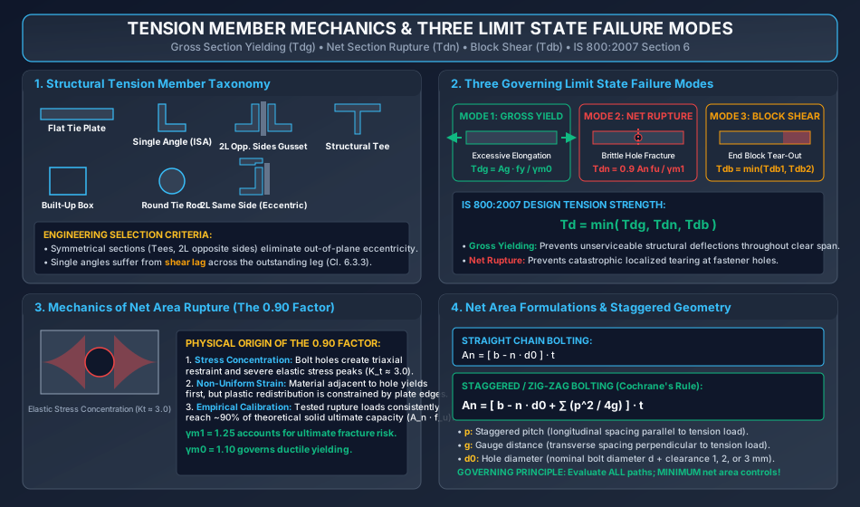
Key Architectural Insights from Figure 1:
- Three-Tier Hierarchy: The capacity of any structural tension member is governed by the minimum of gross yielding, net rupture, and block shear tear-out.
- Ductile vs Brittle Modes: Gross yielding is ductile and visible through span elongation, whereas net rupture is localized and sudden.
- The Factor Calibration: Accounting for high triaxial stress concentrations () and plastic necking constraint, IS 800 incorporates a reduction () into the net rupture equation.
Figure 2: Staggered Bolting Geometry & Critical Net Area Evaluation
+----------------------------------------------------------------------------------------------------+
|                               STAGGERED BOLTING FAILURE PATH ANALYSIS                              |
|                                                                                                    |
|            Path 1: Straight Cut                       Path 2: Zig-Zag Cut                          |
|         +-------------------------+                +-------------------------+                     |
|         |    o               o    |                |    o               o    |                     |
|         |    |                    |                |    | \                  |                     |
|         |    | <--- Line A-B      |                |    |  \ <--- Stagger p  |                     |
|         |    |                    |                |    |   o                |                     |
|         |    o               o    |                |    |  /                 |                     |
|         |                         |                |    o               o    |                     |
|         +-------------------------+                +-------------------------+                     |
|         An1 = (b - 2*d0) * t                       An2 = (b - 3*d0 + 2*p^2/4g) * t                 |
|                                                                                                    |
|         Governing Rupture Area: An = min( An1, An2, An3, ... )                                     |
+----------------------------------------------------------------------------------------------------+
The geometric layout and Cochrane stagger mechanics are illustrated below:
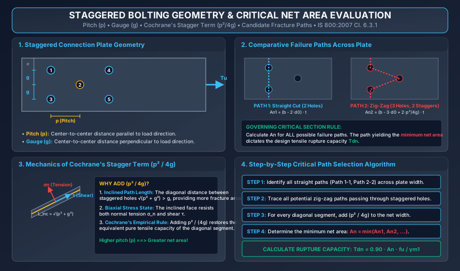
Key Architectural Insights from Figure 2:
- Geometric Stagger Pitch () vs Gauge (): Staggering fasteners increases the net fracture path length from the straight gauge distance to the diagonal hypotenuse .
- Cochrane's Term (): Adding compensates for the shear resistance mobilized along the inclined plane. A larger pitch significantly increases net area.
- Exhaustive Path Evaluation: Every plausible path across the width of the plate must be calculated; the path with the smallest net area dictates the design rupture strength .
7. Step-by-Step Design Procedures & Workflows
7.1 Workflow: Design of an Axially Loaded Tension Tie Plate
[START: Given Factored Tensile Load Tu, Member Length L, Steel Grade]
       |
       v
[Step 1: Estimate Minimum Required Gross Area (Ag,req)]
       --> From gross yielding: Ag,req = (Tu * gamma_m0) / fy
       --> From net rupture estimate: An,req = (Tu * gamma_m1) / (0.90 * fu)
       --> Estimate trial Ag: Ag,trial ≈ An,req / 0.75 to 0.85
       --> Choose trial Ag = max(Ag,req, Ag,trial)
       |
       v
[Step 2: Select Standard Plate / Flat Section]
       --> Select plate width b and thickness t such that b * t >= Ag,trial.
       |
       v
[Step 3: Lay Out Fastener Holes]
       --> Determine bolt size d, compute hole diameter d0.
       --> Choose chain or staggered pattern meeting pitch p >= 2.5d and edge e >= 1.5d0.
       |
       v
[Step 4: Compute Critical Net Area (An)]
       --> Evaluate all candidate straight and zig-zag failure paths.
       --> An = min(An1, An2, ...)
       |
       v
[Step 5: Verify Design Strengths per IS 800:2007]
       --> Tdg = (Ag * fy) / gamma_m0
       --> Tdn = (0.90 * An * fu) / gamma_m1
       --> Td = min(Tdg, Tdn)
       --> Is Td >= Tu?
           |-- NO  --> Increase plate thickness or width; repeat from Step 2.
           |-- YES --> Continue to Step 6.
       |
       v
[Step 6: Slenderness Ratio Check (IS 800 Table 3)]
       --> r_min = t / sqrt(12)  (for rectangular plate)
       --> lambda = L / r_min
       --> Is lambda <= lambda_max (e.g. 400)?
           |-- NO  --> Increase plate thickness t or add lateral ties.
           |-- YES --> SAFE. Proceed to block shear verification. [END]
8. Solved Numerical Examples (Pre-Calculated & Multi-Step)
Problem 1: Plate Tie Capacity — Chain vs Staggered Bolting
Statement: A flat tie plate of cross-section is fabricated from Fe 410 steel (). The plate is connected to a gusset plate using M20 Class 4.6 bolts (). Determine the design tensile strength of the plate under:
- Case A: A chain bolting arrangement with 3 bolts in a single transverse line across the width.
- Case B: A staggered bolting arrangement where the middle bolt is staggered by pitch , with transverse gauge distance between adjacent bolt lines. Compute the percentage increase in net rupture capacity achieved by staggering the bolts.
       Load Tu <=============================== [Plate 300 x 12 mm]
       Case A (Chain):                     Case B (Staggered):
       +-----------------------+           +-----------------------+
       |   o (Hole 1)          |           |   o (Hole 1)          |
       |                       |           |     \                 |
       |   o (Hole 2)          |           |      o (Hole 2, p=50) |
       |                       |           |     /                 |
       |   o (Hole 3)          |           |   o (Hole 3)          |
       +-----------------------+           +-----------------------+
Step 1: Gross Area and Gross Yielding Strength ()
- Gross area:
- Design gross yielding strength:
Step 2: Case A — Chain Bolting (3 Bolts in Straight Line)
- Net width across the transverse line of 3 holes:
- Net area:
- Design rupture strength:
- Governing design capacity for Case A: (Governed by gross section yielding!)
Step 3: Case B — Staggered Bolting () Examine all candidate failure paths:
- Path 1 (Straight path through 2 outer holes 1 and 3):
- Path 2 (Zig-zag path through holes 1-2-3): This path passes through 3 holes () and includes 2 staggered diagonal segments (Hole 1 to 2, and Hole 2 to 3): Net width along Path 2: Net area along Path 2:
- Controlling Net Area for Case B:
- Design rupture strength for Case B:
- Governing design capacity for Case B:
Step 4: Comparison & Percentage Gain
- Increase in net cross-sectional area:
- Increase in net rupture strength:
Conclusion: Staggering the middle bolt increases the net rupture capacity by without changing the plate dimensions.
Problem 2: Evaluation of Multiple Failure Paths in a Staggered Joint
Statement: A flat plate tension member of width and thickness (Fe 410 steel) is connected with M16 bolts (). Four bolt holes are located on three transverse gauge lines:
- Hole 1 and Hole 3 are located on the outer gauge lines at and from the edge.
- Hole 2 is located on the middle gauge line at , staggered longitudinally by relative to Holes 1 and 3. The transverse gauge spacing is . Evaluate the net cross-sectional area along all candidate failure paths, identify the critical path, and determine the governing design tensile strength .
       Edge 0 mm  ------------------------------------------
                     o Hole 1 (y = 40 mm)
       Gauge g = 80 mm
                                o Hole 2 (y = 120 mm, Stagger p = 45 mm)
       Gauge g = 80 mm
                     o Hole 3 (y = 200 mm)
       Edge 240 mm -----------------------------------------
Step 1: Stagger Correction Term For each diagonal segment between consecutive holes with and :
Step 2: Candidate Failure Path Analysis
- Path 1 (Straight path through Holes 1 and 3): This path runs purely transverse, piercing 2 holes with zero staggers:
- Path 2 (Zig-zag path through Holes 1-2-3): This path pierces 3 holes () and traverses 2 diagonal segments (Hole 1 to 2, and Hole 2 to 3):
- Path 3 (Zig-zag path through Holes 1 and 2 only, exiting to edge): This path pierces 2 holes () and has 1 diagonal segment (Hole 1 to 2):
Step 3: Identification of Critical Path Comparing all three candidates:
The controlling net area is along the zig-zag path 1-2-3.
Step 4: Design Tensile Capacities
- Net Section Rupture Strength ():
- Gross Section Yielding Strength ():
- Controlling Design Tensile Strength ():
Conclusion: The connection is governed by gross section yielding (), with the critical net rupture path 1-2-3 providing .
Problem 3: Complete Design of a Flat Tie Plate Tension Member
Statement: Design a flat plate tie member for a roof truss to carry a factored tensile force . The length of the member between joint nodes is . The steel grade is Fe 410 (). The end connection uses M20 Class 4.6 bolts in two rows. Check gross section yielding, net section rupture, and the slenderness ratio per IS 800:2007 Table 3 ().
Step 1: Determine Required Gross Area () From the limit state of gross yielding:
Step 2: Determine Required Net Area () From the limit state of net rupture:
Step 3: Select Trial Plate Section For 2 M20 bolt holes (), the hole deduction is .
- Estimating .
- Select a flat plate of size:
- Actual gross area provided:
Step 4: Check Capacities per IS 800:2007
- Gross Section Yielding Capacity:
- Net Section Rupture Capacity: With 2 M20 bolts arranged in a chain across the width: Since :
- Design Tensile Strength:
Step 5: Check Maximum Slenderness Ratio ()
- For a rectangular plate of width and thickness :
- Member length .
- Slenderness ratio:
- Per IS 800:2007 Table 3, for a general member normally acting as a tie: Since , the member is SAFE against excessive sagging and vibration.
Final Specification: Provide a flat plate (Fe 410 steel) with 2 M20 Class 4.6 bolts in each connection line.
9. Common Pitfalls, Edge Cases & Failure Modes
- Confusing Nominal Bolt Diameter () with Hole Diameter ():
- Pitfall: Subtracting instead of when calculating net area .
- Consequence: Underestimating the area deducted for holes by per hole, leading to an unconservative overestimate of rupture strength.
- Omitting the Zig-Zag Rupture Path in Staggered Connections:
- Pitfall: Evaluating only the straight transverse cut across holes and ignoring the staggered zig-zag path.
- Reality: If the pitch is small or gauge is large, the zig-zag path through more holes almost always controls the design rupture strength.
- Neglecting the Maximum Slenderness Ratio ():
- Pitfall: Designing very thin tie plates (e.g., ) that satisfy tensile strength but have enormous slenderness ratios (), resulting in excessive sag, wind flutter, and site rejection.
- Incorrect Stagger Term Multiplier:
- Pitfall: Adding the stagger term once for a path that contains two diagonal segments.
- Rule: The term must be added for each individual inclined segment traversed along the failure path.
10. Exam-Specific Focus Points & Rapid Revision Notes
10.1 Quick Revision Formula Card
- Gross Yielding: ().
- Net Rupture of Plates: ().
- Straight Net Area: .
- Staggered Net Area: .
- Threaded Rod Rupture: with .
- Governing Tensile Capacity: .
- Rectangular Plate Radius of Gyration: .
- Max Slenderness Table 3:
- Tie subjected to reversal of stress due to wind/earthquake:
- Tie in a roof truss (normally in tension):
- Tension member (other than pretensioned cables):
10.2 Examination Nuances
- GATE CE: Questions typically present a plate with 3 or 4 staggered holes and ask: "What is the critical net area ?" Solve all paths and pick the minimum.
- ESE Prelims: Frequently tests the partial safety factors (), the factor in net rupture, and Table 3 slenderness limits.
- SSC JE & State AE/JE: Direct numericals on Cochrane's formula () and the maximum permissible slenderness ratio ().
11. Practice Problems & Self-Assessment Question Bank
- Question 1 (Conceptual): Why is the partial safety factor for gross section yielding () lower than that for net section rupture ()?
- Answer: Gross section yielding is a ductile failure mode that develops visible elongation across the entire clear length prior to complete failure, providing warning. Net section rupture is a localized, sudden, and non-ductile fracture at fastener holes without warning, requiring a higher safety factor ().
- Question 2 (Formula Application): A tie plate of (Fe 410) has a single hole of diameter . Compute its gross yielding capacity and net rupture capacity .
- Answer: . . Governing capacity .
- Question 3 (GATE Numeric): In a staggered joint with , what staggered pitch is required so that the net width along a zig-zag path across 2 holes equals the net width of a straight cut across 1 hole?
- Answer: Condition: . For and : .
- Question 4 (Slenderness Rule): What is the maximum unsupported length of an Fe 410 flat tie plate of thickness if its maximum slenderness ratio is limited to ?
- Answer: . .
- Question 5 (Rupture vs Yielding): Under what condition does net rupture govern over gross yielding in a plate with bolt holes?
- Answer: . Thus, net rupture governs whenever the hole deductions reduce the net area below of the gross area.
12. Bibliographic References & Standard Codes
- Bureau of Indian Standards: IS 800:2007 — General Construction in Steel — Code of Practice (Third Revision), BIS, New Delhi.
- Subramanian, N.: Design of Steel Structures (Limit State Method), Oxford University Press, 2018.
- Duggal, S. K.: Limit State Design of Steel Structures, McGraw Hill Education (India), 2nd Edition, 2019.
- Bhavikatti, S. S.: Design of Steel Structures By Limit State Method as per IS: 800-2007, I.K. International Publishing House.
- INSDAG: Teaching Resource for Structural Steel Design: Tension Members, Institute for Steel Development & Growth, Kolkata.
- AISC 360-16: Specification for Structural Steel Buildings, American Institute of Steel Construction, Chicago.