Bearing Capacity of Shallow Foundations
In this chapter (5 topics)
On this page
- 1. Module Overview & Learning Objectives
- Primary Learning Objectives:
- 2. Modes of Bearing Capacity Shear Failure
- 3. Terzaghi's Bearing Capacity Theory & Plastic Equilibrium Zones
- Fundamental Theoretical Assumptions:
- The Three Plastic Equilibrium Zones:
- 4. Terzaghi Bearing Capacity Formulations & Shape Effects
- Special Case: Pure Cohesive Soil (Saturated Clay, φ = 0):
- Empirical Shape Modifications (Terzaghi):
- Local Shear Failure Corrections (Terzaghi):
- 5. Precise Definitions of Bearing Capacity Terminology
- 6. Groundwater Fluctuations & IS 6403 Correction Factors
- Exact Effective Stress Mechanics:
- IS 6403:1981 Water Table Correction Factors (Rw1, Rw2):
- 7. Eccentric & Inclined Loading (Meyerhof Effective Width B')
- Contact Pressure Distribution on Base of Width B:
- Meyerhof's Effective Area Method (1953):
- 8. General Bearing Capacity Formulation (Meyerhof, Hansen, Vesic & IS 6403)
- 9. In-Situ Bearing Capacity Determination: Plate Load Test (IS 1888:1982)
- Test Specifications (IS 1888):
- Scale Laws for Bearing Capacity:
- Scale Laws for Settlement:
- 10. Standard Penetration Test (N-Value) & Permissible Settlement Criteria
- Teng's Formulations for Net Allowable Soil Pressure:
- 11. Solved Numerical Problems
- Problem 1: Terzaghi General vs. Local Shear Failure in Square Footing
- Problem 2: Water Table Fluctuations & Eccentric Loading on Rectangular Footing
- Problem 3: Plate Load Test Interpretation & Scale Laws for Sand vs. Clay
- 12. Comparative Engineering Analysis Across Syllabi
- 13. Common Misconceptions & Examination Pitfalls
- 14. Key Reference Formulas & Summary Table
1. Module Overview & Learning Objectives
Foundations serve as the structural interface transferring superstructure loads (dead, live, wind, and seismic) safely into the underlying geologic strata. A foundation is classified as shallow if its embedment depth is less than or equal to its least lateral dimension (, or according to generalized modern practice).
                             SHALLOW FOUNDATION DESIGN CRITERIA
                                             │
                  ┌──────────────────────────┴──────────────────────────┐
                  ▼                                                     ▼
        SHEAR STRENGTH CRITERION                               SETTLEMENT CRITERION
    (Ultimate Bearing Capacity q_u)                        (Allowable Settlement S_all)
                  │                                                     │
        ┌─────────┴─────────┐                                 ┌─────────┴─────────┐
        ▼                   ▼                                 ▼                   ▼
 Modes of Failure    Analytical Theories             Immediate Elastic     Consolidation
 (General, Local,     (Terzaghi, Meyerhof,             Settlement S_i      Settlement S_c
  Punching Shear)      Hansen, IS 6403)                 (Fox, Janbu)     (Terzaghi 1D Theory)
                            │                                       │
                            └───────────────────┬───────────────────┘
                                                ▼
                                    NET ALLOWABLE BEARING PRESSURE
                                   q_na = min(q_ns, q_np)
Primary Learning Objectives:
- Differentiate Shear Failure Modes: Identify General Shear Failure (GSF), Local Shear Failure (LSF), and Punching Shear Failure (PSF) based on relative density (), friction angle (), SPT -value, and stress-strain ductility.
- Derive & Apply Terzaghi's Formulations: Analyze the three plastic equilibrium failure zones (Elastic wedge, Radial shear log-spiral, Linear Rankine passive wedge) and apply shape modifications for strip, square, circular, and rectangular geometries.
- Master Terminology & Definitions: Rigorously distinguish between Gross Pressure (), Ultimate Bearing Capacity (), Net Ultimate (), Net Safe (), Gross Safe (), and Net Allowable Bearing Pressure ().
- Account for Groundwater Fluctuations: Apply exact effective stress mechanics and IS 6403 depth correction factors () for water table positions within the surcharge and shear wedge zones.
- Analyze Eccentric & Inclined Loads: Utilize the Meyerhof effective footprint method () and determine contact pressure distributions under middle-third and detachment regimes.
- Interpret Field Tests: Understand the operational procedure, pressure bulb scale effects, and distinct settlement/capacity scaling laws of the Plate Load Test (IS 1888) and SPT -value correlations for sands versus clays.
2. Modes of Bearing Capacity Shear Failure
Experimental investigations by Vesic (1973) revealed that the mechanism of shear failure beneath shallow foundations is dictated by soil compressibility and relative packing density.
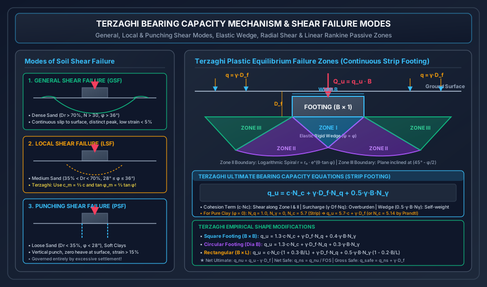
┌────────────────────────────────────────────────────────────────────────────────────────────────────────┐
│                              MODES OF BEARING CAPACITY SHEAR FAILURE                                   │
├─────────────────────┬──────────────────────────────┬─────────────────────────────┬─────────────────────┤
│ Diagnostic Feature  │ General Shear Failure (GSF)  │ Local Shear Failure (LSF)   │ Punching Shear (PSF)│
├─────────────────────┼──────────────────────────────┼─────────────────────────────┼─────────────────────┤
│ Soil Type           │ Dense Sand, Stiff-Hard Clays │ Medium Sand, Medium Clay    │ Loose Sand, Soft    │
│                     │ (D_r > 70%, N > 30, φ > 36°) │ (35% < D_r < 70%, 28°-36°)  │ Clays (D_r < 35%)   │
├─────────────────────┼──────────────────────────────┼─────────────────────────────┼─────────────────────┤
│ Slip Surface        │ Continuous, well-defined,    │ Terminates within soil      │ Vertical shearing   │
│                     │ extends to ground surface    │ mass below footing          │ along perimeter     │
├─────────────────────┼──────────────────────────────┼─────────────────────────────┼─────────────────────┤
│ Surface Heave/Bulge │ Prominent bulging on both    │ Slight heave visible close  │ Zero surface heave; │
│                     │ sides of footing             │ to footing edges            │ continuous downward │
├─────────────────────┼──────────────────────────────┼─────────────────────────────┼─────────────────────┤
│ Load-Settlement     │ Distinct, well-defined peak  │ Progressive yield without   │ Linear-steep plunge,│
│ Curve Character     │ failure load; sudden drop    │ sharp peak; gentle knee     │ never shows peak    │
├─────────────────────┼──────────────────────────────┼─────────────────────────────┼─────────────────────┤
│ Failure Strain      │ Small strains (< 5%)         │ Intermediate strains (10%)  │ Very large (> 15%)  │
├─────────────────────┼──────────────────────────────┼─────────────────────────────┼─────────────────────┤
│ Terzaghi Adjustment │ Use full c and φ directly    │ Reduced parameters:         │ Governed entirely   │
│                     │                              │ c_m = ⅔ c, tan φ_m = ⅔ tan φ│ by settlement       │
└─────────────────────┴──────────────────────────────┴─────────────────────────────┴─────────────────────┘
3. Terzaghi's Bearing Capacity Theory & Plastic Equilibrium Zones
Karl Terzaghi (1943) established the first comprehensive analytical formulation for the ultimate bearing capacity of a shallow, rough, continuous strip footing.
Fundamental Theoretical Assumptions:
- Foundation Geometry: Shallow continuous strip footing (, ), reducing the problem to plane strain.
- Rough Base: High friction between footing base and soil prevents lateral expansion; base soil does not undergo lateral shear.
- Overburden Idealization: The soil mass located above the footing base () is replaced by an equivalent uniform surcharge . Shear resistance of the overburden soil is neglected ( above base level).
- Mohr-Coulomb Criterion: Soil obeys .
- General Shear Regime: Soil behaves as a rigid-plastic continuum.
The Three Plastic Equilibrium Zones:
- Zone I (Elastic Triangular Wedge ):
- Located directly beneath the base of width .
- Because the footing base is rough, soil in Zone I is prevented from shearing laterally and moves vertically downward as an integral unit with the footing.
- For a rough base, the apex angles at and are equal to the soil internal friction angle (wedge sides inclined at to horizontal).
- Zone II (Radial Shear Zones and ):
- Adjacent to the elastic wedge on either side.
- Soil is in a state of plastic shear failure.
- The curved slip boundary and is a logarithmic spiral defined by: where is the length of side (or ), and is the angle subtended with .
- Zone III (Linear Rankine Passive Wedges and ):
- Outer triangular zones extending to the footing base level.
- Soil is pushed laterally and upward against the overburden surcharge .
- The slip planes and are straight lines inclined at to the horizontal.
4. Terzaghi Bearing Capacity Formulations & Shape Effects
By superimposing the contributions of soil cohesion (), surcharge (), and soil self-weight () within the shear zone, Terzaghi expressed the ultimate bearing capacity for a continuous strip footing:
where are dimensionless Terzaghi Bearing Capacity Factors, dependent solely on the soil friction angle :
(Note: Prandtl and Reissner derived and . Terzaghi's values are slightly higher for rough strip footings).
Special Case: Pure Cohesive Soil (Saturated Clay, ):
For undrained loading ():
- (Terzaghi rough strip base) or (Prandtl smooth base).
Key Invariant: For a strip footing on saturated pure clay (), the net ultimate bearing capacity is completely independent of foundation width and depth !
Empirical Shape Modifications (Terzaghi):
To extend the 2D strip footing equation to 3D footing geometries, Terzaghi introduced empirical shape factors:
-
Square Footing ():
For pure clay (): .
-
Circular Footing (Diameter ):
-
Rectangular Footing (, with ):
Local Shear Failure Corrections (Terzaghi):
If the soil is loose to medium dense sand or soft/medium clay exhibiting Local Shear Failure, the mobilization of shear strength along the spiral boundary is incomplete. Terzaghi prescribed modified shear strength parameters:
The ultimate bearing capacity is computed using modified bearing capacity factors evaluated at :
5. Precise Definitions of Bearing Capacity Terminology
In foundation design and examination evaluations, precise differentiation between gross and net pressures is paramount:
┌────────────────────────────────────────────────────────────────────────────────────────────────────────┐
│                               BEARING CAPACITY PRESSURE DEFINITIONS                                    │
├───────────────────────────────┬──────────────────────┬─────────────────────────────────────────────────┤
│ Terminology                   │ Symbol               │ Analytical Definition                           │
├───────────────────────────────┼──────────────────────┼─────────────────────────────────────────────────┤
│ 1. Gross Intensity of Loading │ q                    │ Total downward pressure at base: q = Q / A      │
│ 2. Overburden Pressure        │ q_0 = σ_v0           │ Effective/total initial vertical stress: γ·D_f   │
│ 3. Ultimate Bearing Capacity  │ q_u or q_ult         │ Minimum gross pressure causing shear failure    │
│ 4. Net Ultimate Bearing Cap.  │ q_nu                 │ Net excess pressure causing shear failure:      │
│                               │                      │ q_nu = q_u - γ·D_f                              │
│ 5. Net Safe Bearing Capacity  │ q_ns                 │ Safe net pressure with factor of safety FOS:    │
│                               │                      │ q_ns = q_nu / FOS = (q_u - γ·D_f) / FOS         │
│ 6. Gross Safe Bearing Capacity│ q_safe               │ Maximum allowable gross pressure against shear: │
│                               │                      │ q_safe = q_ns + γ·D_f = (q_nu / FOS) + γ·D_f    │
│ 7. Net Safe Settlement Press. │ q_np                 │ Net pressure limiting settlement to S_allowable │
│ 8. Net Allowable Bearing Press│ q_na                 │ Governing design pressure:                      │
│                               │                      │ q_na = min(q_ns, q_np)                          │
└───────────────────────────────┴──────────────────────┴─────────────────────────────────────────────────┘
Critical Distinction: Factor of Safety (, typically ) is applied strictly to the net ultimate bearing capacity , not to the overburden surcharge , because the excavated soil weight was already supported in-situ by the ground prior to construction.
6. Groundwater Fluctuations & IS 6403 Correction Factors
Water table location alters effective stresses both in the surcharge zone () and within the shear wedge zone ().
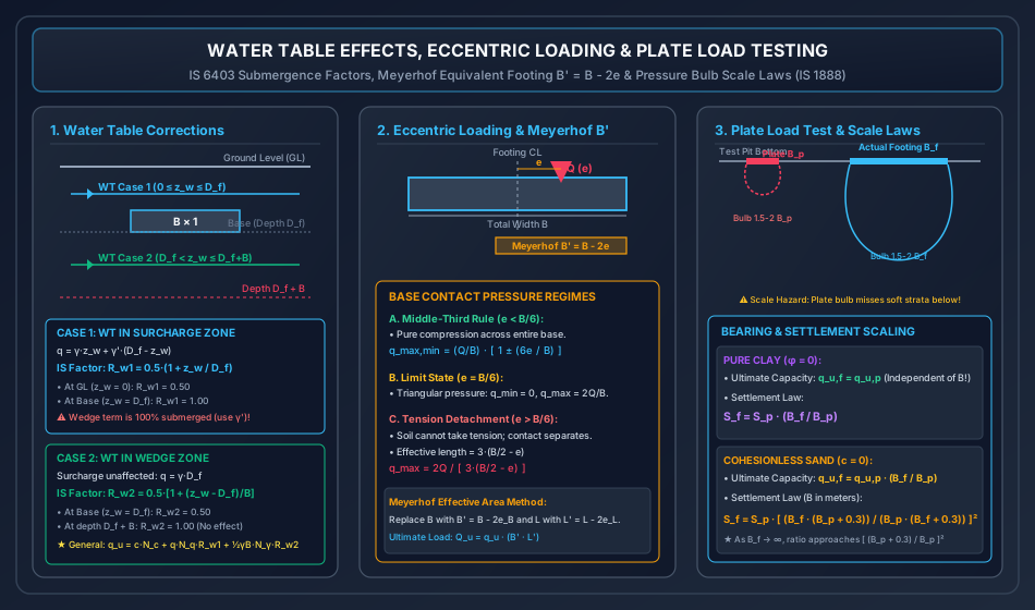
Exact Effective Stress Mechanics:
-
Case 1: Water Table in Surcharge Zone ():
- Upper soil of depth has bulk/moist unit weight .
- Lower soil of depth is submerged ().
- Effective surcharge at footing base:
- Because the water table is above the footing base, the entire shear wedge beneath the footing () is fully submerged. Therefore, the wedge term uses the submerged unit weight:
-
Case 2: Water Table in Wedge Zone ():
- Surcharge is entirely above the water table: (unaffected).
- The shear failure zone extends to approximately depth below the base. The weighted effective unit weight within the wedge is:
-
Case 3: Water Table Deep Below Base ():
- Water table is outside the plastic shear failure zone. Zero effect on bearing capacity: and .
IS 6403:1981 Water Table Correction Factors ():
IS 6403 provides simplified linear reduction factors applied to the surcharge and wedge terms:
where:
- is the depth of water table below ground surface ().
- is the depth of water table below footing base ().
- When water table rises to the ground surface (): , cutting the surcharge and wedge capacities by .
7. Eccentric & Inclined Loading (Meyerhof Effective Width )
When columns transmit bending moments () alongside axial loads (), the vertical resultant acts with an eccentricity .
Contact Pressure Distribution on Base of Width :
The contact pressure distribution is governed by the middle-third rule:
- Within Middle-Third (): Entire base remains in compression. Trapezoidal distribution:
- At Kern Boundary (): Triangular pressure distribution with at the heel and at the toe.
- Beyond Kern (): Soil cannot sustain tensile stress. The heel detaches from the soil, producing a shortened triangular contact zone of length :
Meyerhof's Effective Area Method (1953):
Meyerhof proved that an eccentrically loaded footing behaves identically to a centrally loaded footing having reduced, effective dimensions:
- The ultimate bearing capacity is computed using the effective width in the wedge term () and in shape/depth factor formulas.
- The total ultimate vertical load the footing can support is:
8. General Bearing Capacity Formulation (Meyerhof, Hansen, Vesic & IS 6403)
Modern codes synthesize Terzaghi's theory with rigorous shape, depth, and inclination adjustments:
┌────────────────────────────────────────────────────────────────────────────────────────────────────────┐
│                              IS 6403:1981 MODIFICATION FACTORS MATRIX                                  │
├─────────────────────┬─────────────────────────────────────┬────────────────────────────────────────────┤
│ Factor Type         │ Cohesion Term (c·N_c)               │ Surcharge / Wedge (N_q, N_γ)               │
├─────────────────────┼─────────────────────────────────────┼────────────────────────────────────────────┤
│ Shape Factors (s)   │ s_c = 1 + 0.2·(B/L) [Strip: 1.0,    │ s_q = 1 + 0.2·(B/L)                        │
│                     │       Square: 1.3, Circle: 1.3]     │ s_γ = 1 - 0.4·(B/L) [Square: 0.8, Cir: 0.6]│
├─────────────────────┼─────────────────────────────────────┼────────────────────────────────────────────┤
│ Depth Factors (d)   │ d_c = 1 + 0.2·(D_f/B)·√N_φ          │ d_q = d_γ = 1 + 0.1·(D_f/B)·√N_φ (φ > 10°) │
│                     │ where N_φ = tan²(45° + φ/2)         │ d_q = d_γ = 1.0 (for φ = 0)                │
├─────────────────────┼─────────────────────────────────────┼────────────────────────────────────────────┤
│ Inclination Factors │ i_c = i_q = (1 - α/90°)²            │ i_γ = (1 - α/φ)²                           │
│ (Load at angle α)   │                                     │                                            │
└─────────────────────┴─────────────────────────────────────┴────────────────────────────────────────────┘
9. In-Situ Bearing Capacity Determination: Plate Load Test (IS 1888:1982)
The Plate Load Test is an on-site testing procedure to evaluate the ultimate bearing capacity and settlement of soils under a rigid test plate.
Test Specifications (IS 1888):
- Test Plate: Square or circular flat steel plate, thickness , sizes ranging from to ( is standard).
- Test Pit: Width of test pit must be at least (), excavated to foundation depth .
- Loading Procedure: Load applied via hydraulic jack against a reaction truss or kentledge platform. Initial seating load . Load increments applied in stages (typically of expected safe capacity) until failure or total settlement reaches (sands) or (clays).
Scale Laws for Bearing Capacity:
-
Pure Cohesive Clay (): Because has no width term ():
Ultimate bearing capacity is identical for the plate and the full-scale footing!
-
Cohesionless Sand (): Because , the second term dominates:
Scale Laws for Settlement:
-
Pure Cohesive Clay: Elastic and primary consolidation settlement vary directly with width:
-
Cohesionless Sand (Terzaghi & Peck Formula): Due to confining stress increase with depth beneath larger footings:
(where and are expressed in meters).
Limitations & Scale Effects of Plate Load Test:
- Scale Effect (Pressure Bulb Depth): The isobar of significant stress () extends to depth under the plate ( for a plate). However, beneath a large foundation (), the bulb penetrates . If a soft clay lens exists at depth, the plate test will completely fail to detect it, leading to disastrous overestimation of safety!
- Time Effect in Clays: A plate load test is completed within hours to days, measuring only immediate elastic settlement . It captures zero long-term primary consolidation settlement , which requires years.
10. Standard Penetration Test (-Value) & Permissible Settlement Criteria
In cohesionless soils, allowable bearing pressures are predominantly governed by settlement criteria ( for isolated footings, for rafts) rather than shear failure.
Teng's Formulations for Net Allowable Soil Pressure:
For permissible maximum settlement ():
where:
- is net allowable bearing pressure in (or multiply by for ).
- is corrected SPT -value ( or ).
- is footing width in meters.
- is the depth factor.
- is the water table factor.
11. Solved Numerical Problems
Problem 1: Terzaghi General vs. Local Shear Failure in Square Footing
Statement: A square column footing of size is founded at depth in a homogeneous soil stratum with:
- Bulk unit weight:
- Cohesion:
- Internal friction angle:
Terzaghi's bearing capacity factors for (General Shear) are:
Modified factors for Local Shear Failure are:
(a) Assuming General Shear Failure, calculate the ultimate bearing capacity , net ultimate bearing capacity , net safe bearing capacity , and gross safe column load using a factor of safety .
(b) If the stratum is composed of loose to medium dense soil susceptible to Local Shear Failure, compute the mobilized soil parameters and , the revised , and the revised gross safe column load .
Solution:
(a) General Shear Failure Analysis: For a square footing (), Terzaghi's equation is:
Calculating each term:
- Cohesion term:
- Surcharge term:
- Soil self-weight (wedge) term:
Summing terms:
- Initial overburden surcharge:
- Net ultimate bearing capacity:
- Net safe bearing capacity ():
- Gross safe bearing capacity:
- Safe column load:
(b) Local Shear Failure Analysis:
- Mobilized cohesion:
- Mobilized friction angle:
Using modified factors :
- Term 1:
- Term 2:
- Term 3:
Summing terms:
- Net ultimate:
- Net safe ():
- Gross safe:
- Revised safe column load:
Comparative Finding: Local shear failure reduces the safe load capacity by (from to ), highlighting why identifying failure mode is paramount in loose-medium deposits!
Problem 2: Water Table Fluctuations & Eccentric Loading on Rectangular Footing
Statement: A rectangular footing of size is founded at depth in a clean cohesionless sand deposit (, ). Geotechnical properties:
- Moist/bulk unit weight above water table:
- Saturated unit weight:
- Submerged unit weight:
- Terzaghi bearing capacity factors for : .
Terzaghi rectangular shape correction:
(a) Case 1: The water table is at depth below ground level (deep). Calculate and .
(b) Case 2: Heavy monsoons raise the water table to below the ground surface ( above the footing base). Calculate the new ultimate bearing capacity and the percentage reduction compared to Case 1.
(c) Case 3: The water table rises to the ground surface (). Concurrently, the column transmits an eccentric vertical load with eccentricity along the width (). Using Meyerhof's effective area method, evaluate whether the footing safely supports the load with .
Solution:
(a) Case 1: Deep Water Table: Given: .
- Shape factor:
- Surcharge term:
- Wedge term:
Summing terms:
(b) Case 2: Water Table at Below Ground Surface ( Above Base):
- Upper soil of thickness has .
- Lower soil of thickness has .
- Effective surcharge at footing base:
- Surcharge capacity term:
- Because water table is at depth, the entire shear wedge beneath the footing () is 100% submerged. Hence, use :
Summing terms:
- Percentage reduction in ultimate bearing capacity:
(c) Case 3: Water Table at Ground Surface () & Eccentric Load ():
- Check middle-third: Entire base is in compression (no tension detachment).
- Meyerhof effective dimensions:
- Revised shape factor with :
- Water table at surface:
Ultimate bearing capacity:
- Total ultimate load capacity:
- Gross safe load capacity ():
Design Verification:
Applied design load .
Actual Factor of Safety:
Problem 3: Plate Load Test Interpretation & Scale Laws for Sand vs. Clay
Statement: A Plate Load Test was performed in an exploratory pit at a planned foundation depth of using a standard square steel plate of dimensions (). The load-settlement observations indicated:
- Ultimate bearing capacity of the plate:
- Settlement of the plate under a test intensity of :
A full-scale square building column foundation of size is to be constructed at the same embedment depth and will impose a working intensity of .
(a) Case A: Saturated Cohesive Clay (): Determine the ultimate bearing capacity and the anticipated settlement of the full-scale footing.
(b) Case B: Cohesionless Clean Sand (): Determine the ultimate bearing capacity and the anticipated settlement of the full-scale footing using Terzaghi-Peck scale laws.
Solution:
Given: .
Width ratio: .
(a) Case A: Saturated Cohesive Clay ():
- In pure clay, bearing capacity is independent of footing size because :
- Settlement scales linearly with width:
(b) Case B: Cohesionless Clean Sand ():
- In clean sand, ultimate bearing capacity is directly proportional to width ():
- Settlement scales non-linearly according to the Terzaghi-Peck empirical formulation: Substitute values in meters:
┌────────────────────────────────────────────────────────────────────────────────────────────────────────┐
│                                SUMMARY COMPARISON: CLAY VS. SAND                                       │
├─────────────────────┬──────────────────────────────┬─────────────────────────────┬─────────────────────┤
│ Soil Type           │ Plate Value (B_p = 0.3 m)    │ Footing Value (B_f = 2.4 m) │ Scaling Factor      │
├─────────────────────┼──────────────────────────────┼─────────────────────────────┼─────────────────────┤
│ Clay (φ = 0):       │                              │                             │                     │
│ • Ultimate Capacity │ 450.0 kPa                    │ 450.0 kPa                   │ 1.0× (Identical)    │
│ • Settlement        │ 8.5 mm                       │ 68.0 mm                     │ 8.0× (Linear B_f/B_p│
├─────────────────────┼──────────────────────────────┼─────────────────────────────┼─────────────────────┤
│ Sand (c = 0):       │                              │                             │                     │
│ • Ultimate Capacity │ 450.0 kPa                    │ 3600.0 kPa                  │ 8.0× (Linear B_f/B_p│
│ • Settlement        │ 8.5 mm                       │ 26.86 mm                    │ 3.16× (Non-linear)  │
└─────────────────────┴──────────────────────────────┴─────────────────────────────┴─────────────────────┘
12. Comparative Engineering Analysis Across Syllabi
┌────────────────────────────────────────────────────────────────────────────────────────────────────────┐
│                        SYLLABUS EMPHASIS & EXAMINATION FOCUS MATRIX                            │
├─────────────┬─────────────────────────────────────────────────┬────────────────────────────────────────┤
│ Examination │ High-Yield Core Focus Areas                     │ Typical Question Typology              │
├─────────────┼─────────────────────────────────────────────────┼────────────────────────────────────────┤
│ GATE CE     │ • Water table correction factors (exact vs IS)  │ NAT numericals on Meyerhof B' = B-2e;  │
│             │ • Local vs General shear failure criteria       │ settlement scaling in sand vs clay;    │
│             │ • Pure clay bearing capacity independent of B   │ Terzaghi shape factor substitutions    │
├─────────────┼─────────────────────────────────────────────────┼────────────────────────────────────────┤
│ UPSC ESE    │ • Analytical derivation of Terzaghi equations   │ 15-20 mark conventional questions      │
│             │ • Failure zone spiral and Rankine geometries    │ deriving failure zones; IS 6403 shape/ │
│             │ • Plate load test procedure, pressure bulbs,    │ depth/inclination factor tables        │
│             │   and scale limitations (IS 1888)               │                                        │
├─────────────┼─────────────────────────────────────────────────┼────────────────────────────────────────┤
│ SSC JE &    │ • Terzaghi formulas for strip, square, circle   │ Quick MCQs: N_c for pure clay = 5.7;   │
│ RRB JE      │ • Pure clay strip q_u = 5.7c + γDf              │ water table at GL cuts capacity by 50%;│
│             │ • Plate test size 300 mm to 750 mm              │ pit width ≥ 5 B_p                      │
├─────────────┼─────────────────────────────────────────────────┼────────────────────────────────────────┤
│ State AE/JE │ • Net safe vs gross safe bearing capacity       │ Direct numericals calculating safe load│
│             │ • Middle-third rule for eccentricity e ≤ B/6    │ Q_safe; SPT N-value settlement bounds  │
└─────────────┴─────────────────────────────────────────────────┴────────────────────────────────────────┘
13. Common Misconceptions & Examination Pitfalls
-
Applying Factor of Safety to Overburden Surcharge:
- Trap: Writing .
- Reality: Surcharge represents soil weight that was already fully in equilibrium prior to excavation. Factor of safety applies strictly to net ultimate capacity:
-
Plate Load Test Validity for Clay Footings:
- Trap: Assuming the Plate Load Test accurately measures total foundation settlement in deep clay strata.
- Reality: The plate test is rapid (hours), measuring only immediate elastic settlement . It captures zero primary consolidation settlement . Furthermore, the pressure bulb of a plate penetrates only , completely missing deeper compressible clay beds that a wide foundation will stress!
-
Bearing Capacity of Footings in Clay vs. Width:
- Trap: Believing that widening a footing on clay increases its ultimate bearing capacity .
- Reality: For pure clay (), . Hence, . Widening the footing increases total load capacity , but the stress intensity remains completely unchanged!
-
Eccentricity in Shape Factors:
- Trap: Using full dimensions and in shape factor formulas when the load is eccentric.
- Reality: According to Meyerhof and IS 6403, all shape factors () and the wedge dimension must utilize the effective dimensions and .
-
Water Table Correction Factor When Water Table is Deep:
- Trap: Applying when the water table is at depth .
- Reality: The shear failure zone extends only to depth beneath the base (). If water table is deeper than , (no reduction).