Soil Formation, Three-Phase System, Phase Relationships & Volumetric/Mass Properties
In this chapter (8 topics)
On this page
- 1. Topic Metadata & Syllabus Anchors
- 2. Executive Summary & Geological Origin of Soils
- 2.1 The Definition of Soil in Civil Engineering
- 2.2 Soil Genesis: Weathering Processes
- 2.3 Geological Classification of Transported & Special Soil Deposits
- 3. Three-Phase Representation & Physical Models
- 3.1 Limiting Two-Phase Boundary States
- 4. Fundamental Phase Ratios & Volumetric / Mass Properties
- 4.1 Volumetric Phase Ratios
- 4.2 Gravimetric (Weight) & Mass Phase Ratios
- 4.3 Unit Weights & Densities
- 5. Rigorous Analytical Derivations & Functional Relationships
- 5.1 Derivation 1: Equivalence Between Void Ratio (e) and Porosity (n)
- 5.2 Derivation 2: The Golden Soil Mechanics Identity (S · e = w · Gs)
- 5.3 Derivation 3: General Expression for Bulk Unit Weight (γ)
- 5.4 Derivation 4: Dry Unit Weight (γd) Relationships
- 5.5 Derivation 5: Saturated (γsat) and Submerged (γ') Unit Weights
- 5.6 Critical Hydraulic Gradient (ic) & Quick Condition Connection
- 5.7 Relative Density (Density Index, ID)
- 6. Borrow-Pit Excavation, Embankment Fill & Volumetric Mass Balance
- 6.1 The Solid Volume Invariance Principle
- 6.2 Moisture Requirement for Compaction
- 7. Visual Vector Graphics & Engineering Schematics
- 7.1 Soil Three-Phase System & Fundamental Relationships
- 7.2 Borrow-Pit to Embankment Mass Balance & Relative Density Mechanics
- 8. Laboratory & Field Determination Methods (IS 2720)
- 8.1 Water Content Determination Methods (IS 2720 Part 2)
- 8.2 Specific Gravity Determination (IS 2720 Part 3)
- 8.3 In-Situ Unit Weight Determination Methods
- 9. Step-by-Step Pre-Calculated Numerical Examples
- Problem 1: Comprehensive Phase Ratios, Saturation & Submergence
- Problem 2: Multi-Pit Earthwork Optimization & Water Requirement
- Problem 3: Relative Density, In-Situ Packing & Critical Hydraulic Gradient
- 10. Common Exam Traps, Failure Modes & Field Gotchas
- The 5 Critical Traps in Soil Phase Relationships
- 11. Multi-Exam Targeted Practice Questions
- Question 1 (GATE CE Computational)
- Question 2 (UPSC ESE Conventional - 10 Marks)
- Question 3 (SSC JE Rapid Recall)
- Question 4 (State AE Objective)
- Question 5 (RRB JE Technical)
- 12. Reference Standards & Authoritative Handbooks
1. Topic Metadata & Syllabus Anchors
| Attribute | Specification |
|---|---|
| Topic ID | GEOTECH-01-01 |
| Subject Module | Subject 09: Geotechnical Engineering & Foundation Engineering |
| Chapter | Chapter 01: Soil Nature, Three-Phase Relationships & Volumetric-Gravimetric Properties |
| GATE CE Syllabus | Origin of soils, soil structure and fabric; Three-phase system and phase relationships, index properties; Weight-volume relationships, relative density |
| UPSC ESE Syllabus | Paper-II Section D (Geo-technical Engineering): Soil types and formation, phase relationships, definitions of moisture content, unit weights, void ratio, porosity, degree of saturation, inter-relationships |
| SSC JE / RRB JE / State AE | Soil formation, types of soils (residual & transported), 3-phase diagram, definitions of void ratio, porosity, saturation, densities, simple relationships, borrow pit problems |
| Primary Codes & Standards | IS 2720 (Part 1 to 41): Methods of Test for Soils; IS 1498:1970: Classification and Identification of Soils for General Engineering Purposes |
| Master Note Path | notes/geotechnical_engineering/01_soil_mechanics/01_soil_formation_phase_relationships.md |
2. Executive Summary & Geological Origin of Soils
2.1 The Definition of Soil in Civil Engineering
In geotechnical engineering, soil is defined as the uncemented or weakly bonded aggregate of mineral grains, rock fragments, and decayed organic matter, with liquid and gas occupying the inter-particle pore spaces. Unlike geology (which views soil merely as the thin surficial weathering mantle supporting vegetation), civil engineering treats soil as an engineered foundation material, a slope-forming natural medium, or an earthwork construction material (embankments, dams, subgrades, and retaining fills).
2.2 Soil Genesis: Weathering Processes
Soils originate from parent rocks through the continuous geological cycle of weathering, transportation/erosion, deposition, and upheaval:
- Mechanical (Physical) Weathering:
- Induced by temperature fluctuations (freeze-thaw frost wedging, thermal expansion/contraction cycles), wind abrasion, flowing water scouring, glacier grinding, and plant root action.
- Yields coarse-grained, non-cohesive soils (boulders, cobbles, gravels, sands, and coarse non-plastic silts).
- Key Characteristic: The mineralogical composition of the soil grains remains identical to that of the parent rock (e.g., quartz, feldspar). Particle shapes are bulky, angular, sub-rounded, or rounded.
- Chemical Weathering:
- Induced by chemical reactions with atmospheric water and gases: hydration, carbonation, oxidation, reduction, and hydrolysis/leaching.
- Yields fine-grained, cohesive soils (plastic silts and crystalline clay minerals such as kaolinite, illite, and montmorillonite).
- Key Characteristic: The chemical and mineralogical crystal lattice is completely transformed. Particles have enormous specific surface areas and are electrically charged (colloidal behavior governed by surface forces rather than gravitational mass forces).
                      ┌─────────────────────────────────┐
                      │          PARENT ROCK            │
                      └────────────────┬────────────────┘
                                       │
                    ┌──────────────────┴──────────────────┐
                    ▼                                     ▼
        [ Physical Weathering ]               [ Chemical Weathering ]
        • Temperature, Frost, Wind            • Hydration, Carbonation, Hydrolysis
        • Coarse-Grained Soils                • Fine-Grained Soils (Clay Minerals)
        • Gravitational Force Dominates       • Surface Electric Charges Dominate
                    │                                     │
                    └──────────────────┬──────────────────┘
                                       │
                    ┌──────────────────┴──────────────────┐
                    ▼                                     ▼
           [ RESIDUAL SOILS ]                    [ TRANSPORTED SOILS ]
           Remain at site of formation           Carried by geological agents
           (Pedological profile: gradational     (Classified by transport medium)
            weathering crust over bedrock)
2.3 Geological Classification of Transported & Special Soil Deposits
The engineering behavior of natural soil deposits is governed by their transport mechanism, depositional energy regime, and sedimentation environment:
| Soil Type | Geological Transport Agent / Depositional Environment | Engineering Characteristics & Exam Identification Markers |
|---|---|---|
| Alluvial Soil | Running river water (Alluvium) | Deposited in river beds, floodplains, and deltas. Layered, sorted, varying from coarse gravel/sand to fine silt/clay. High fertility, variable permeability. |
| Lacustrine Soil | Calm, still fresh-water lakes | Deposited under quiescent conditions. Characterized by varved clays (alternating micro-layers of summer silts/sands and winter colloidal clays). |
| Marine Soil | Saline ocean / sea water | High sodium and marine salts. Very soft, highly compressible, low shear strength upon disturbance. Sensitive clays with open flocculated marine structure. |
| Aeolian Soil (Loess & Dunes) | Wind transport | Dune sand: uniformly graded, rounded sand. Loess: wind-blown, calcareous, silt-sized deposits exhibiting vertical cleavage; susceptible to severe collapse upon wetting (collapsible soil). |
| Glacial Till / Drift | Glacial ice movement and melting | Highly unsorted, unstratified heterogeneous mixture containing everything from giant rock boulders down to pulverized rock flour (boulder clay). High density due to glacial preloading. |
| Colluvial Soil (Talus) | Gravity creep down mountain slopes | Accumulations of coarse, angular rock fragments at cliff bases. Highly unstable, susceptible to landslides. |
| Bentonite Clay | Chemical alteration of volcanic ash | Predominantly montmorillonite. Possesses enormous swelling upon wetting, extreme shrinkage on drying, high plasticity, and thixotropic gel behavior (used as drilling mud). |
| Black Cotton Soil | Residual weathering of volcanic basalt rock | Found across Central & Western India (Deccan trap). Rich in montmorillonite. Exhibits extreme volumetric shrinkage and swelling cracks during seasonal moisture changes. Notorious for foundation heave. |
| Peat & Muck | Accumulation of decomposed organic matter | Peat: highly fibrous, fully organic, dark brown/black, exceptionally high natural moisture content (), extreme compressibility. Muck: mixture of organic matter and inorganic silt/clay. |
| Caliche & Hardpan | Chemical cementation of gravel/sand/silt | Cemented by calcium carbonate or iron oxides precipitated by evaporating groundwater. Extremely dense, rock-like resistance to excavation. |
3. Three-Phase Representation & Physical Models
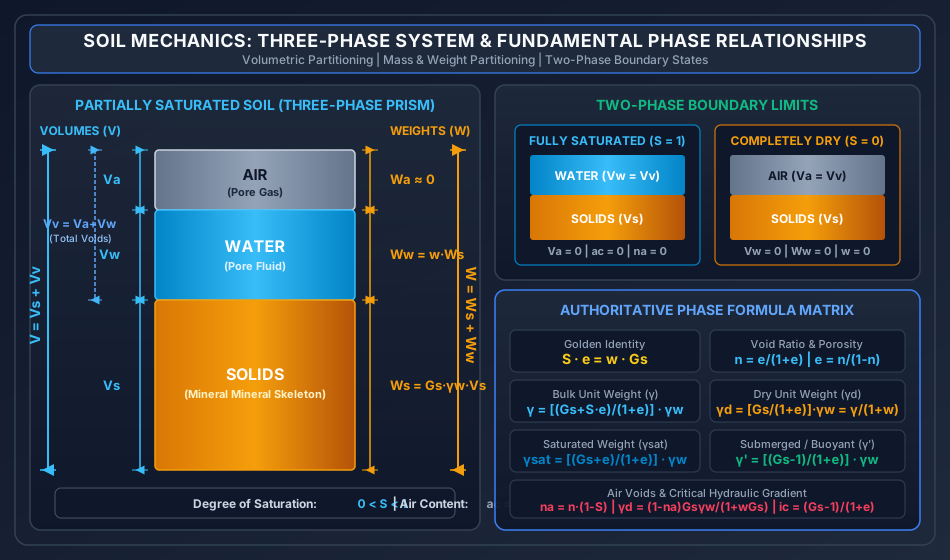
Natural soil consists of a porous skeletal matrix formed by mineral grains, with interconnected voids filled with pore water and pore air. In 1943, Karl Terzaghi established the Three-Phase Soil Model, which separates the complex continuous multiphase structure into three equivalent discrete ideal phases:
- Solid Phase (Mineral Skeleton): Incompressible mineral grains of volume and dry weight .
- Liquid Phase (Pore Water): Water occupying part or all of the pore space, having volume and weight .
- Gas Phase (Pore Air): Air and water vapor occupying the remainder of the voids, having volume and negligible mass/weight ().
        VOLUME PARTITIONING                     MASS / WEIGHT PARTITIONING
        ┌───────────────────┐    ▲              ┌───────────────────┐    ▲
        │                   │    │              │                   │    │
        │      AIR (Va)     │    │              │      AIR (Wa ≈ 0) │    │
        │                   │    │ Vv           ├───────────────────┤    │
        ├───────────────────┤    │ (Total       │                   │    │ W
        │                   │    │  Voids)      │     WATER (Ww)    │    │ (Total
        │     WATER (Vw)    │    │              │                   │    │  Weight)
        │                   │    ▼              ├───────────────────┤    │
        ├───────────────────┤    ─              │                   │    │
        │                   │    ▲              │                   │    │
        │                   │    │              │                   │    │
        │     SOLIDS (Vs)   │    │ Vs           │     SOLIDS (Ws)   │    │
        │                   │    │              │                   │    │
        │                   │    ▼              │                   │    ▼
        └───────────────────┘    ─              └───────────────────┘    ─
        ◄──────── V ────────►                   ◄──────── W ────────►
3.1 Limiting Two-Phase Boundary States
Natural soils transition between three-phase and two-phase states based on environmental and groundwater conditions:
- Fully Saturated Soil ( or ):
- The groundwater table submerges the stratum, or capillary action pulls water into all voids.
- Air volume vanishes: .
- The soil reduces to a two-phase system (Solids + Water).
- Completely Dry Soil ():
- After oven-drying at or under arid desert conditions.
- Water evaporates completely: and .
- The soil reduces to a two-phase system (Solids + Air).
4. Fundamental Phase Ratios & Volumetric / Mass Properties
Geotechnical engineering defines dimensionless volumetric and gravimetric ratios that characterize the state of compaction, moisture content, and mass density of soils.
4.1 Volumetric Phase Ratios
| Property | Symbol | Mathematical Definition | Valid Numerical Range | Physical Significance & Engineering Insight |
|---|---|---|---|---|
| Void Ratio | Ratio of void volume to solid skeleton volume. Preferred in theoretical soil mechanics because remains constant during consolidation, compaction, or shear deformation. | |||
| Porosity | () | Ratio of void volume to total volume. Preferred in fluid hydraulics and groundwater seepage (). Bound strictly below unity. | ||
| Degree of Saturation | or | () | Volume fraction of voids filled with water. for oven-dry soil; for partially saturated soil; for fully saturated soil. | |
| Air Content | Volume fraction of voids filled with air. By definition, . | |||
| Percentage Air Voids | () | Ratio of air void volume to total soil volume. Relates directly to porosity and air content: . |
4.2 Gravimetric (Weight) & Mass Phase Ratios
| Property | Symbol | Mathematical Definition | Valid Numerical Range | Physical Significance & Engineering Insight |
|---|---|---|---|---|
| Water Content (Moisture Content) | (Can exceed ) | Ratio of pore water weight to oven-dry solid weight. Expressed as percentage. Fine marine clays, quick clays, and organic peats routinely have up to . | ||
| Specific Gravity of Soil Solids | or | (Typical: ) | Absolute specific gravity of the solid mineral grains referenced to pure water at (). | |
| Apparent (Mass) Specific Gravity | Specific gravity of the overall soil mass including all voids. Always smaller than because voids add volume without proportional solid mass (). |
4.3 Unit Weights & Densities
- Bulk Unit Weight ( or ):
- Dry Unit Weight (): The premier index of field soil compaction: the denser the particle packing, the higher the dry unit weight.
- Saturated Unit Weight (): Bulk unit weight when all voids are flooded with water ().
- Submerged (Buoyant) Unit Weight ( or ): By Archimedes' principle, every unit volume submerged beneath the groundwater table experiences an upward buoyant force equal to . As a general rule of thumb, .
5. Rigorous Analytical Derivations & Functional Relationships
Every volumetric and gravimetric soil property can be derived analytically by considering a unit volume of soil solids () or a unit total volume ().
5.1 Derivation 1: Equivalence Between Void Ratio () and Porosity ()
Proof: By definition of total volume: . Dividing both sides by :
Now, express porosity :
Dividing numerator and denominator by :
To invert the relationship, take the reciprocal:
5.2 Derivation 2: The Golden Soil Mechanics Identity ()
Proof: Let the volume of solid grains be .
- From the definition of void ratio: .
- From the definition of degree of saturation: .
- The weight of pore water is:
- From the definition of specific gravity: . The weight of solids is:
- From the definition of moisture content:
Rearranging directly:
[!NOTE] For a fully saturated soil (), the relationship reduces to:
This provides an immediate, foolproof method to compute void ratio directly from moisture content in fully saturated soil layers.
5.3 Derivation 3: General Expression for Bulk Unit Weight ()
Proof: Consider a soil element with solid volume :
- Volume of voids:
- Total volume:
- Weight of solids:
- Volume of water:
- Weight of water:
- Total weight of soil:
Dividing total weight by total volume:
Substituting the identity :
5.4 Derivation 4: Dry Unit Weight () Relationships
Proof: In dry soil, and :
From bulk unit weight:
Derivation in terms of Percentage Air Voids (): Total volume . Dividing by :
Substitute , , and :
Rearranging for :
[!TIP] The Zero Air Voids Line (ZAVL) represents the theoretical maximum dry density achievable at any moisture content, corresponding to zero air voids ( or ):
5.5 Derivation 5: Saturated () and Submerged () Unit Weights
Proof: Setting in the general bulk unit weight equation:
Submerged unit weight by Archimedes' principle:
In terms of porosity , since :
5.6 Critical Hydraulic Gradient () & Quick Condition Connection
When upward seepage occurs through a saturated soil stratum, the upward seepage force balances the submerged weight of the soil solids. At this threshold, effective stress becomes zero (), and the soil completely loses its shear strength (boiling or quick sand condition):
For typical sands with and :
5.7 Relative Density (Density Index, )
Relative density is the premier parameter used to quantify the state of packing and relative compactness of cohesionless granular soils (sands and gravels):
where:
- void ratio in the loosest possible laboratory state (determined per IS 2720 Part 14 by pouring dry sand slowly through a funnel).
- void ratio in the densest possible laboratory state (achieved via vibration under surcharge).
- natural in-situ void ratio of the deposit.
Conversion to Dry Densities: Since :
Dividing:
| Relative Density () | Descriptive Compactness Class (IS 1498) | Angle of Internal Friction () | Standard Penetration Resistance (-value) |
|---|---|---|---|
| Very Loose | |||
| Loose | |||
| Medium Dense | |||
| Dense | |||
| Very Dense |
6. Borrow-Pit Excavation, Embankment Fill & Volumetric Mass Balance
A frequent civil engineering task in highway, railway, and earthen dam construction is calculating the required volume of soil to be excavated from a natural borrow pit to construct an engineered embankment fill of designated compacted volume and density.
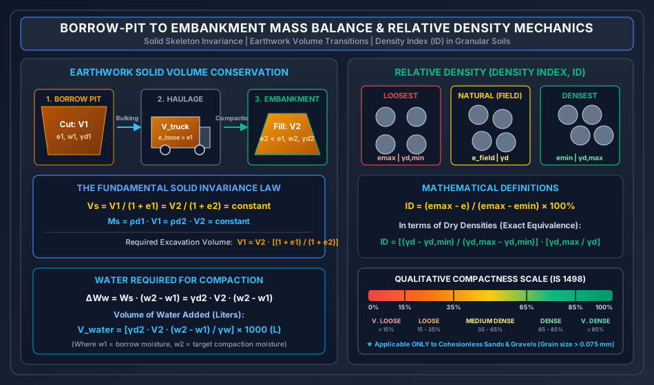
       NATURAL BORROW PIT                     HAUL TRUCKS                   ENGINEERED EMBANKMENT
        (In-situ Cut)                      (Loose Bulking)                     (Compacted Fill)
     ┌──────────────────┐                ┌──────────────────┐                ┌──────────────────┐
     │ Volume: V1       │  Excavation    │ Volume: V_truck  │  Compaction    │ Volume: V2       │
     │ Void ratio: e1   │ ─────────────► │ Bulking Factor:B │ ─────────────► │ Void ratio: e2   │
     │ Moisture: w1     │   & Hauling    │ e_loose > e1     │   & Rolling    │ Moisture: w2     │
     │ Dry density:γd1  │                │                  │                │ Dry density:γd2  │
     └──────────────────┘                └──────────────────┘                └──────────────────┘
       ◄────────────── SOLID MINERAL SKELETON REMAINS CONSTANT (Vs1 = Vs2) ──────────────►
       ◄──────────────── DRY MASS OF SOIL SOLIDS IS CONSERVED (Ms1 = Ms2) ───────────────►
6.1 The Solid Volume Invariance Principle
During excavation, transport, spreading, and roller compaction, only pore air and pore water are expelled or added. The net volume and mass of solid mineral grains remains completely invariant:
Since :
Equating solid volumes:
In terms of dry unit weights:
6.2 Moisture Requirement for Compaction
Borrow pit soil is excavated at natural moisture content , but must be compacted at the optimum moisture content (). The weight of water present in the borrow pit excavation:
The weight of water required in the compacted embankment:
Net additional water to be hauled and sprinkled:
Volume of water to be added:
7. Visual Vector Graphics & Engineering Schematics
7.1 Soil Three-Phase System & Fundamental Relationships
The vector schematic below illustrates the three-phase prism, volume and weight partitionings, two-phase boundary limits, and the master governing equations:
7.2 Borrow-Pit to Embankment Mass Balance & Relative Density Mechanics
The engineering diagram below depicts the solid skeleton conservation during earthwork operations alongside the relative density spectrum of granular deposits:
8. Laboratory & Field Determination Methods (IS 2720)
8.1 Water Content Determination Methods (IS 2720 Part 2)
| Method | Apparatus & Procedure | Standard Control & Temperature | Suitability, Accuracy & Exam Traps |
|---|---|---|---|
| Oven-Drying Method (Standard Reference) | Thermostatically controlled oven; soil dried to constant mass (16–24 hrs). | Inorganic soils: . Organic soils: to avoid oxidation. Gypsum soils: to avoid loss of crystal water (). |
Most accurate laboratory method. Exam Trap: If gypsum soil is heated above , structural water of crystallization is lost, yielding falsely elevated moisture content. |
| Pycnometer Method | 1000 ml glass jar with brass cone (6 mm orifice). Four weighings (). | Ambient lab temperature. Requires prior knowledge of specific gravity . | Rapid (15–20 mins). Suitable ONLY for coarse-grained cohesionless soils where entrapped air can be easily removed. Unsuitable for fine clays. |
| Sand Bath Method | Field method; open tray heated over a sand bath and kerosene stove. | Visual monitoring; no precise temperature control. | Rapid field method for highway sites. Soil may overheat, causing structural organic decomposition. |
| Alcohol Method | Methylated spirit added to soil clods in an evaporating dish and ignited. | Direct flaming combustion. | Rapid field method (10 mins). Unsuitable for soils containing significant organic content or calcium compounds. |
| Calcium Carbide (Rapid Moisture Meter) | Sealed pressure chamber; moisture reacts with producing acetylene gas (): . | Pressure gauge calibrated directly to give water content on wet weight basis (). | Fastest field method (5 minutes). Used for compaction control. Formula: . |
| Nuclear / Radiation Method | Radioactive probe () emitting fast neutrons inserted into soil. | Hydrogen nuclei thermalize (slow down) neutrons. | Non-destructive, continuous field monitoring. High initial equipment cost and radiation hazard protocols. |
Mathematical Derivation of Pycnometer Moisture Formula:
Mass of wet soil: . Mass of water added in bottle 3: . Volume of water added in bottle 3: . Volume of soil solids: . Since :
The mass of water is . Therefore, water content :
8.2 Specific Gravity Determination (IS 2720 Part 3)
Determined using a 50 ml density bottle or pycnometer:
where , , , . All entrapped air must be evacuated under a vacuum desiccator or boiled gently.
8.3 In-Situ Unit Weight Determination Methods
| Method (Standard) | Principle & Field Procedure | Suitability & Constraints |
|---|---|---|
| Core Cutter Method (IS 2720 Part 29) | A cylindrical steel cutter ( volume, 100 mm dia, 130 mm height) driven into ground using a rammer and dolly. Soil trimmed and weighed. | Strictly for soft, fine-grained cohesive soils free of stones. Unusable in gravelly, sandy, or very hard dry soils (causes cutter damage or edge shattering). |
| Sand Replacement Method (IS 2720 Part 28) | A small test hole (100–150 mm dia) excavated; excavated soil weighed. Hole backfilled with dry, calibrated, uniformly graded standard sand (passing 1 mm, retained 600 m) from a pouring cylinder. Volume calculated from sand mass. | Universal method: highly accurate for all soils including gravelly, stony, coarse, and fissured strata. Standard for road subgrade quality control. |
| Water Displacement Method (IS 2720 Part 33) | Cohesive undisturbed soil clod trimmed, weighed, coated with impermeable molten paraffin wax, weighed again, and submerged in a water displacement container. | Cohesive soils only. Wax coating prevents water absorption into voids (). |
9. Step-by-Step Pre-Calculated Numerical Examples
Problem 1: Comprehensive Phase Ratios, Saturation & Submergence
Statement: A partially saturated undisturbed soil specimen has a total volume of and a total mass of . The moisture content determined by oven drying is . The specific gravity of soil solids is . Assuming and , determine:
- Bulk density () and bulk unit weight ().
- Dry density () and dry unit weight ().
- Void ratio (), porosity (), and degree of saturation ().
- Air content () and percentage air voids ().
- Mass of water (in kg) that must be added to of this soil stratum to achieve complete saturation without change in void ratio.
- Saturated unit weight () and submerged unit weight ().
Detailed Step-by-Step Solution:
Step 1: Calculate Mass Components and Densities
- Total volume:
- Total mass:
- Moisture content:
Bulk density:
Bulk unit weight:
Dry mass of soil solids:
Mass of pore water:
Dry density:
Dry unit weight:
Step 2: Volumetric Partitioning Volume of soil solids:
Volume of voids:
Volume of water:
Volume of air:
Step 3: Void Ratio, Porosity, and Saturation Void ratio:
Porosity:
Cross-check: (Verified).
Degree of saturation:
Cross-check via identity: (Verified).
Step 4: Air Content and Percentage Air Voids Air content:
Percentage air voids:
Cross-check: (Verified).
Step 5: Additional Mass of Water to Saturate of Soil In of this soil, the volume occupied by air voids is:
To reach full saturation (), all air voids must be filled with water:
Step 6: Saturated and Submerged Unit Weights Saturated unit weight:
Submerged unit weight:
Cross-check: (Verified).
Problem 2: Multi-Pit Earthwork Optimization & Water Requirement
Statement: A highway earthen embankment requires of compacted fill. The design specifications demand a compacted dry unit weight at an optimum moisture content . The specific gravity of soil solids is . Three borrow pits (A, B, and C) are available with differing properties and haulage costs:
| Borrow Pit | In-Situ Void Ratio () | Natural Water Content () | All-Inclusive Cost per Excavated (INR) |
|---|---|---|---|
| Pit A | ₹ | ||
| Pit B | ₹ | ||
| Pit C | ₹ |
- Calculate the total volume of soil () that must be excavated from each pit to build the embankment.
- Determine which borrow pit provides the most economical source of earthwork fill.
- For the most economical pit, compute the total volume of water (in Liters) that must be added during field compaction.
Detailed Step-by-Step Solution:
Step 1: Embankment Solid Inventory & Void Ratio Total dry weight of solids required in the embankment:
Embankment void ratio:
Net volume of soil solids:
Step 2: Excavation Volume Required from Each Pit Using the solid volume invariance formula :
- Pit A ():
- Pit B ():
- Pit C ():
Step 3: Total Cost Comparison
- Total Cost for Pit A:
- Total Cost for Pit B:
- Total Cost for Pit C:
Step 4: Water Addition Required for Pit C Natural moisture in Pit C: . Required compaction moisture: . Weight of water to be added:
Volume of water in :
Volume of water in Liters:
Problem 3: Relative Density, In-Situ Packing & Critical Hydraulic Gradient
Statement: Laboratory density tests conducted on a clean, sub-angular river sand () yielded:
- Maximum void ratio in loosest state: ().
- Minimum void ratio in densest state: ().
An in-situ field core-cutter test at the proposed foundation bed yielded a field dry density .
- Compute the natural in-situ void ratio ().
- Calculate the relative density () using both the void ratio definition and the dry density formula, proving their equivalence.
- Classify the compactness state of the sand deposit as per IS 1498.
- If this foundation bed is submerged with the groundwater table at the ground surface and is subjected to upward seepage flow, calculate the critical hydraulic gradient () that will trigger quicksand boiling failure.
Detailed Step-by-Step Solution:
Step 1: In-Situ Void Ratio
Step 2: Relative Density () Computation Method A: From Void Ratio Definition:
Method B: From Dry Density Formulation:
Step 3: Compactness Classification Referring to the IS 1498 criteria:
- Medium Dense
- Dense
Since , the natural river sand deposit is classified as Dense Sand. It possesses excellent bearing capacity, high internal friction angle (), and low liquefaction susceptibility.
Step 4: Critical Hydraulic Gradient () The critical hydraulic gradient at which effective stress vanishes:
An upward hydraulic gradient exceeding will fluidize the sand, causing complete bearing failure.
10. Common Exam Traps, Failure Modes & Field Gotchas
[!WARNING]
The 5 Critical Traps in Soil Phase Relationships
- The Moisture Content Basis Trap:
- Moisture content in geotechnical engineering is strictly defined with respect to dry solid weight ():
- In environmental/chemical engineering, moisture is often defined on total weight:
- Trap: If a problem states "the moisture content is on total weight basis," never use directly in ! First convert: ().
- Void Ratio vs. Porosity Range Limits:
- Porosity is a fraction of the total volume (), meaning it is mathematically bounded: (or ).
- Void ratio is a ratio of voids to solids (). It can easily exceed (or )! Bentonites and sensitive marine clays regularly exhibit .
- Never assume cannot exceed .
- The Oven-Drying Gypsum Trap (IS 2720 Part 2):
- Standard drying temperature is .
- If the soil contains gypsum (), this high temperature strips the chemically bound crystal water, transforming it to hemihydrate ().
- The recorded dry mass will be falsely low, making the calculated water content falsely high!
- Rule: For gypsum-bearing or organic soils, dry strictly at .
- Conservation of Total Volume Fallacy in Earthwork:
- Students frequently compute borrow pit volume by writing: or attempting a direct ratio of bulk unit weights ().
- Fatal Error: Total volume changes drastically due to roller compaction expelling air voids!
- Only the solid volume and dry solid mass remain constant. Always use:
- Relative Density Application Boundary:
- Relative density () is strictly valid only for coarse-grained cohesionless soils (sands and gravels, particles ).
- It is completely meaningless and invalid for clays and plastic silts because cohesive inter-particle electrochemical forces prevent free pouring into an state.
11. Multi-Exam Targeted Practice Questions
Question 1 (GATE CE Computational)
A soil sample in its natural state has a dry density of and a moisture content of . When the sample is completely submerged in water, its saturated unit weight becomes . Assuming , what is the specific gravity () of the soil solids?
- (A)
- (B)
- (C)
- (D)
Correct Answer: (C)
Step-by-Step Derivation:
- Substitute :
- Plug in values: Using standard GATE value :
Question 2 (UPSC ESE Conventional - 10 Marks)
Derive from first principles the expression for dry unit weight () in terms of percentage air voids (), specific gravity of solids (), water content (), and unit weight of water ():
Explain why the compaction curve of any soil never crosses the Zero Air Voids Line.
Model Answer: Derivation:
- Consider a total soil volume . By definition, the total volume is partitioned into solids, water, and air:
- Divide both sides by total volume :
- By definition of percentage air voids: . Thus:
- Express solid volume and water volume in terms of weights:
- Substitute these into step 3:
- Recognizing that dry unit weight :
- Rearranging directly yields:
Physical Explanation for Zero Air Voids Line (ZAVL): The ZAVL represents the theoretical condition of ( saturation, ). In field compaction, dynamic roller energy expels pore air, driving the soil closer to saturation. However, as the air voids reduce to small, discontinuous, occluded bubbles surrounded by pore water, the permeability to air drops to near zero, trapping the remaining air. Expelling this residual occluded air requires infinite compaction energy. Therefore, air expulsion can never be achieved by mechanical compaction alone, and real compaction curves always lie strictly below the ZAVL.
Question 3 (SSC JE Rapid Recall)
If the degree of saturation of a soil is , what is its air content ()?
- (A)
- (B)
- (C)
- (D) Indeterminate without porosity
Correct Answer: (A)
Explanation: Air content is defined as .
Question 4 (State AE Objective)
A soil has a void ratio . Its porosity is:
- (A)
- (B)
- (C)
- (D)
Correct Answer: (B)
Explanation: ().
Question 5 (RRB JE Technical)
The method of water content determination most suitable for rapid field compaction control on a highway construction site within 5 minutes is:
- (A) Oven drying method
- (B) Sand bath method
- (C) Calcium carbide (Rapid moisture meter) method
- (D) Pycnometer method
Correct Answer: (C) Calcium carbide (Rapid moisture meter) method
Explanation: The calcium carbide method generates acetylene gas in a sealed chamber whose pressure is calibrated directly to moisture content within 3 to 5 minutes, making it the industry standard for fast field checks.
12. Reference Standards & Authoritative Handbooks
- Bureau of Indian Standards:
- IS 2720 (Part 1): 1983 – Preparation of Dry Soil Samples for Various Tests.
- IS 2720 (Part 2): 1973 – Determination of Water Content (Oven drying, sand bath, alcohol, and rapid moisture meter).
- IS 2720 (Part 3/Sec 1 & 2): 1980 – Determination of Specific Gravity of Fine, Medium and Coarse Grained Soils.
- IS 2720 (Part 14): 1983 – Determination of Density Index (Relative Density) of Cohesionless Soils.
- IS 2720 (Part 28): 1974 – Determination of Dry Density of Soils in-place by Sand Replacement Method.
- IS 2720 (Part 29): 1975 – Determination of Dry Density of Soils in-place by Core Cutter Method.
- IS 1498: 1970 – Classification and Identification of Soils for General Engineering Purposes.
- Authoritative Geotechnical Treatises:
- Karl Terzaghi, Ralph B. Peck, and Gholamreza Mesri, Soil Mechanics in Engineering Practice, 3rd ed., John Wiley & Sons.
- Gopal Ranjan and A. S. R. Rao, Basic and Applied Soil Mechanics, New Age International Publishers.
- B. C. Punmia, Ashok Kumar Jain, and Arun Kumar Jain, Soil Mechanics and Foundations, 16th ed., Laxmi Publications.
- T. William Lambe and Robert V. Whitman, Soil Mechanics, SI Version, John Wiley & Sons.