Lateral Earth Pressures (At-Rest, Rankine & Coulomb), Tension Cracks & Retaining Wall Stability
In this chapter (5 topics)
On this page
- 1. Module Overview & Learning Objectives
- Core Exam Focus Areas
- 2. Earth Pressure Regimes & Wall Displacement Mechanics
- 2.1 The At-Rest State (K0)
- 2.2 The Active State (Ka)
- 2.3 The Passive State (Kp)
- 3. Rankine's Earth Pressure Theory (1857)
- 3.1 Assumptions of Rankine's Theory
- 3.2 Rankine Active Earth Pressure
- 3.3 Rankine Passive Earth Pressure
- 4. Active Pressure Distributions (Surcharge, Layering & Groundwater)
- 5. Visual Master Diagram: Tension Cracks & Retaining Wall Stability
- 6. Tension Cracks in Cohesive Backfill & Rainwater Surcharge
- 6.1 Tensile Stress Zone & Tension Crack Depth (z0)
- 6.2 Critical Depth of Unsupported Vertical Cut (Hc)
- 6.3 Active Thrust Cases for Cohesive Soils
- 7. Coulomb's Wedge Theory (1776)
- 7.1 Key Characteristics & Differences from Rankine
- 7.2 Coulomb Active Earth Pressure Coefficient (Ka)
- 8. Graphical Methods: Culmann's & Rebhann's Constructions
- 8.1 Rebhann's Graphical Construction (1871)
- 8.2 Culmann's Graphical Method (1866)
- 9. Stability Analysis of Retaining Walls (IS 1904 & IS 14458)
- 9.1 Check 1: Factor of Safety Against Overturning
- 9.2 Check 2: Factor of Safety Against Sliding
- 9.3 Check 3: Base Pressure Distribution & Middle-Third Rule
- 10. Solved Numerical Problems (Step-by-Step, Pre-Calculated)
- Problem 1: Multi-Layered Backfill with Surcharge, Water Table & Submerged Sand (GATE CE / UPSC ESE)
- Problem 2: Cohesive Backfill with Tension Crack & Rainwater Thrust (GATE CE / SSC JE)
- Problem 3: Stability Analysis of Concrete Gravity Retaining Wall (UPSC ESE / State AE)
- 11. Comparative Engineering Analysis & Multi-Exam Question Patterns
- 12. Common Misconceptions, Pitfalls & Pro-Tips
- Critical Traps to Avoid in Competitive Exams
- 13. Key Reference Formulas & Summary Table
1. Module Overview & Learning Objectives
Lateral earth pressure is the horizontal force exerted by a soil mass upon an adjacent retaining structure. The magnitude and spatial distribution of this pressure dictate the structural sizing and foundation design of gravity retaining walls, cantilever reinforced concrete walls, bridge abutments, basement diaphragm walls, sheet pile bulkheads, and braced trench excavations.
+----------------------------------------------------------------------------------------------------+
|                                THE THREE LATERAL EARTH PRESSURE REGIMES                            |
+----------------------+----------------------+----------------------+-------------------------------+
| STATE                | COEFFICIENT          | WALL MOVEMENT (Delta)| PHYSICAL MECHANISM            |
+----------------------+----------------------+----------------------+-------------------------------+
| At-Rest State        | K_0 = 1 - sin(phi')  | Zero displacement    | Elastic confined strain;      |
|                      |                      | (Delta = 0)          | unyielding basement walls.    |
+----------------------+----------------------+----------------------+-------------------------------+
| Active State         | K_a = (1-sin phi') / | Moves AWAY from soil | Soil expands laterally; shear |
| (Minimum Thrust)     |       (1+sin phi')   | (Delta/H ~ 0.1-0.2%) | mobilized; failure wedge slips|
+----------------------+----------------------+----------------------+-------------------------------+
| Passive State        | K_p = (1+sin phi') / | Pushed INTO soil     | Soil compressed laterally;    |
| (Maximum Resistance) |       (1-sin phi')   | (Delta/H ~ 2.0-5.0%) | huge passive resistance built |
+----------------------+----------------------+----------------------+-------------------------------+
Core Exam Focus Areas
- GATE CE: Multi-layered backfill calculations with water tables, surface surcharges, and friction angle discontinuities; Tension crack depth () and critical height of unsupported cut (); Active thrust before vs. after tension cracking, and the catastrophic impact of rainwater filling the tension crack; Middle-third rule for base eccentricity ().
- UPSC ESE: Detailed comparison of Rankine's conjugate stress method vs. Coulomb's rigid wedge limit equilibrium method; Slip plane inclinations (); Graphic solutions (Culmann's and Rebhann's constructions); Complete stability analysis of concrete gravity retaining walls against overturning, sliding, and foundation bearing punch-through.
- SSC JE / State AE / RRB JE: Formula memory: , ; Jaky's formula ; Minimum wall displacement required to mobilize active () vs. passive (); Magnitude ranking: .
2. Earth Pressure Regimes & Wall Displacement Mechanics
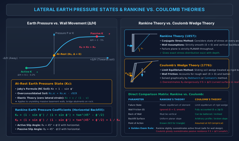
The lateral earth pressure mobilized against a retaining wall is not an intrinsic constant of the soil; it is a dynamic function of the direction and magnitude of the wall's horizontal displacement ():
2.1 The At-Rest State ()
When a retaining wall is completely rigid, unyielding, and fixed against both translation and rotation (), the backfill soil remains in its undisturbed natural state of zero lateral strain (). The ratio of horizontal effective stress to vertical effective stress is defined as the coefficient of earth pressure at rest ():
Formulations for :
- Jaky's Empirical Formula (1944) for Normally Consolidated Cohesionless & Cohesive Soils:
- Overconsolidated Soils (Mayne & Kulhawy, 1982): (In heavily overconsolidated clays with , can exceed !).
- Elastic Theory (Zero Lateral Strain Continuum): Where is Poisson's ratio ( for soils ).
2.2 The Active State ()
When the retaining wall tilts or translates horizontally away from the backfill:
- The soil mass expands horizontally. Lateral confining stress decreases while vertical overburden stress remains constant.
- The Mohr stress circle expands until it touches the Mohr-Coulomb failure envelope.
- At this state of plastic equilibrium, the soil shears along slip planes, forming a sliding wedge. The lateral pressure reaches its minimum possible value—the active earth pressure ().
- Wall Movement Required: Very small displacement—typically ( of wall height) for dense sands, and up to for soft clays.
2.3 The Passive State ()
When the retaining wall is driven or forced horizontally into the backfill mass:
- The soil is compressed laterally. Lateral stress increases until it exceeds the vertical stress and reaches the upper failure envelope limit.
- The soil reaches passive plastic equilibrium, resisting wall penetration with the maximum possible force—the passive earth pressure ().
- Wall Movement Required: Considerably larger displacement—typically ( of wall height), roughly the active displacement.
- Magnitude Inequality: For typical soils ():
3. Rankine's Earth Pressure Theory (1857)
William John Macquorn Rankine formulated his classical theory based on the state of plastic equilibrium in a semi-infinite soil mass.
3.1 Assumptions of Rankine's Theory
- The backfill soil is homogeneous, isotropic, and semi-infinite.
- The backfill surface is planar (either horizontal or inclined at a uniform angle ).
- The backface of the retaining wall is strictly vertical.
- The back of the wall is perfectly smooth (frictionless, ). No shear stresses develop along the soil-wall interface; therefore, vertical and horizontal planes remain principal planes.
- The soil is in a state of plastic failure throughout the failure wedge.
3.2 Rankine Active Earth Pressure
At any depth , the vertical effective overburden stress is the major principal stress:
The active horizontal stress is the minor principal stress:
From the Mohr-Coulomb principal stress relation at failure:
Solving for :
Defining the Rankine Active Earth Pressure Coefficient:
Therefore:
3.3 Rankine Passive Earth Pressure
In the passive state, the lateral pressure forced into the backfill becomes the major principal stress (), while vertical stress is the minor principal stress ():
Defining the Rankine Passive Earth Pressure Coefficient:
Therefore:
4. Active Pressure Distributions (Surcharge, Layering & Groundwater)
When computing the lateral earth pressure distribution on a retaining wall, different environmental boundary conditions must be superposed:
+------------------------------------+---------------------------------------------------------------+
| BOUNDARY CONDITION                 | LATERAL PRESSURE EQUATION & DISTRIBUTION                      |
+------------------------------------+---------------------------------------------------------------+
| 1. Uniform Surcharge (q) at Surface| sigma_a(z) = Ka * q + Ka * gamma * z                          |
|                                    | Adds a UNIFORM RECTANGLE of intensity Ka * q across all depth.|
+------------------------------------+---------------------------------------------------------------+
| 2. Multi-Layered Backfill Stratum  | At boundary interface: vertical effective stress sigma_v' is  |
|    (Layer 1: phi_1, Layer 2: phi_2)| continuous, but lateral pressure sigma_a' exhibits a SHARP    |
|                                    | KINK/DISCONTINUITY due to the step-change in Ka (Ka1 vs Ka2).|
+------------------------------------+---------------------------------------------------------------+
| 3. Submerged Backfill with Water   | Soil effective stress uses submerged unit weight (gamma').   |
|    Table at Depth H_w              | Total lateral thrust = Soil Thrust (Ka * gamma' * z)          |
|                                    |                      + Full Hydrostatic Water (gamma_w * z_w).|
|                                    | Notice: Water pressure is isotropic; it is NOT reduced by Ka! |
+------------------------------------+---------------------------------------------------------------+
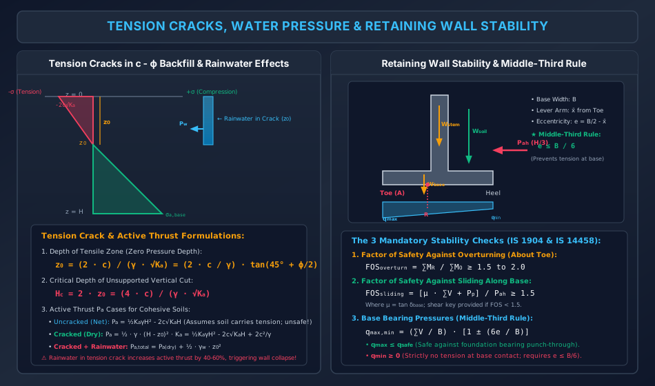
5. Visual Master Diagram: Tension Cracks & Retaining Wall Stability
The following architectural diagram illustrates the stress distribution and mechanics of tension cracks in cohesive backfill, the devastating effect of rainwater filling the crack, the free-body diagram of forces acting on a concrete retaining wall, and the middle-third eccentricity rule.
6. Tension Cracks in Cohesive Backfill & Rainwater Surcharge
For a cohesive-frictional soil ( backfill), the Rankine active pressure equation is:
6.1 Tensile Stress Zone & Tension Crack Depth ()
- At ground surface ():
- Because soil possesses virtually zero tensile strength, tensile stresses produce open vertical fissures termed tension cracks.
- The depth at which lateral pressure transitions from tension to compression () is found by setting :
6.2 Critical Depth of Unsupported Vertical Cut ()
In a cohesive soil, an open trench can stand vertically without any lateral bracing up to a critical height where the net total active thrust across the face is zero ():
(For pure saturated clay with : ).
6.3 Active Thrust Cases for Cohesive Soils
-
Case A: Before Tension Crack Develops (Theoretical Net Thrust):
Warning: This equation assumes that the tensile stress pulls on the back of the wall, which is physically impossible (soil separates from wall). Using this net value is dangerously unconservative!
-
Case B: After Tension Crack Develops (Dry Crack): The tensile zone () carries zero stress. The active thrust is the positive compression triangle acting from to :
Line of action: Acts at above the base of the wall.
-
Case C: Tension Crack Filled with Rainwater (Monsoon Collapse Condition): During heavy rainfall, open tension cracks fill with water. The hydrostatic water pressure acts directly inside the crack, adding a massive lateral thrust:
Total active thrust on wall:
This water pressure increases the overturning force by , explaining why most retaining wall collapses occur during sudden monsoon rainstorms.
7. Coulomb's Wedge Theory (1776)
Charles-Augustin de Coulomb formulated an alternative earth pressure theory based on the limit equilibrium of a rigid sliding soil wedge.
7.1 Key Characteristics & Differences from Rankine
- Wall Friction (): Coulomb explicitly accounts for friction along the rough soil-wall interface. Typical design values:
- Wall Batter (): Back of wall can be battered or inclined at angle to horizontal.
- Backfill Slope (): Accommodates sloping ground surfaces with angle .
- Force Inclination: The active thrust acts at an angle to the normal to the backface of the wall.
7.2 Coulomb Active Earth Pressure Coefficient ()
For cohesionless soil ():
For a vertical wall () with horizontal backfill ():
8. Graphical Methods: Culmann's & Rebhann's Constructions
When the backfill geometry is irregular, stepped, carries point loads, or possesses broken slopes, analytical equations become intractable. Graphical methods provide exact solutions based on Coulomb's wedge theory:
8.1 Rebhann's Graphical Construction (1871)
Based on Poncelet's theorem, Rebhann's method identifies the critical failure plane without trial-and-error by constructing a triangle on the ground line whose area directly yields the active thrust.
8.2 Culmann's Graphical Method (1866)
Culmann's method represents a direct graphical application of the force equilibrium polygon ():
- Draw the retaining wall backface and the ground surface to a convenient spatial scale.
- From the heel , draw the -line inclined at angle to the horizontal.
- From the heel , draw the -line inclined at angle to the -line (where is the wall inclination angle).
- Select trial failure wedges (); compute their respective gravitational weights ().
- Plot these weights to a force scale along the -line from heel .
- From each weight point on the -line, draw lines parallel to the -line to intersect the corresponding trial slip lines.
- The locus of these intersection points forms the Culmann curve.
- A tangent drawn to the Culmann curve parallel to the -line identifies the point of maximum active thrust ().
9. Stability Analysis of Retaining Walls (IS 1904 & IS 14458)
A retaining wall must satisfy three mandatory structural stability criteria under all combinations of dead loads, earth pressures, surcharges, and water tables:
9.1 Check 1: Factor of Safety Against Overturning
Overturning tends to occur by pivoting about the downstream toe (Point ):
Where:
- is the sum of stabilizing resisting moments about the toe (due to self-weight of wall blocks and vertical soil weight on the heel slab ).
- is the sum of destabilizing overturning moments about the toe (due to horizontal active earth thrust , water thrust , and surcharge).
9.2 Check 2: Factor of Safety Against Sliding
Sliding tends to occur horizontally along the base contact:
Where:
- is the total vertical force acting on the foundation base.
- is the coefficient of base friction (typically ).
- is the total horizontal destabilizing driving thrust.
- is passive earth resistance in front of the toe (often conservatively neglected or halved unless guaranteed unexcavated).
- Remedial Design: If , a shear key is projected below the base slab to mobilize deep passive resistance.
9.3 Check 3: Base Pressure Distribution & Middle-Third Rule
The resultant vertical force acts at an eccentricity from the centerline of the base slab:
The Middle-Third Rule:
To prevent tensile detachment and separation between the wall base and the foundation soil, the resultant must fall within the middle third of the base width:
Base Pressure Equations:
- Maximum Pressure (at Toe):
- Minimum Pressure (at Heel):
10. Solved Numerical Problems (Step-by-Step, Pre-Calculated)
Problem 1: Multi-Layered Backfill with Surcharge, Water Table & Submerged Sand (GATE CE / UPSC ESE)
A retaining wall with a vertical, smooth backface of height retains a two-layered sand backfill supporting a uniform surface surcharge of . The geotechnical properties are:
- Layer 1 (Top to ): Dry sand, , , .
- Layer 2 ( to , thickness ): Submerged sand, regional water table at depth. , , . .
Determine:
- The active earth pressure coefficients and .
- The vertical effective stress and lateral active pressure at , (in Layer 1 and in Layer 2), and .
- The total lateral active thrust () per metre length of wall and its line of action () above the base.
Solution:
Step 1: Compute Earth Pressure Coefficients & Unit Weights
Step 2: Effective Vertical Stresses & Lateral Active Pressures
-
At ground surface ():
-
At depth (in Layer 1, just above water table):
-
At depth (in Layer 2, just below water table):
(Notice the instantaneous drop from to due to higher friction angle in Layer 2!)
-
At base of wall ():
Step 3: Thrust Components and Moment about Base ()
-
Layer 1 ():
- Rectangle: , lever arm
- Triangle: , lever arm
-
Layer 2 ():
- Soil Rectangle: , lever arm
- Soil Triangle: , lever arm
- Hydrostatic Water Triangle: , lever arm
Step 4: Total Lateral Thrust and Line of Action
Problem 2: Cohesive Backfill with Tension Crack & Rainwater Thrust (GATE CE / SSC JE)
A smooth vertical retaining wall of height retains a cohesive-frictional soil with:
- Calculate the active earth pressure coefficient and the depth of the tension crack ().
- Determine the critical depth of an unsupported vertical cut ().
- Compute the total active thrust () after tension cracks develop in dry condition.
- Compute the total active thrust () if the tension crack fills completely with rainwater (), and determine the percentage increase in total thrust.
Solution:
Step 1: Active Earth Pressure Coefficient & Tension Crack Depth
Step 2: Critical Unsupported Height
Step 3: Total Active Thrust After Tension Crack Develops (Dry Condition) At the base ():
The active thrust is the positive compression triangle extending from depth to :
Step 4: Thrust with Rainwater in Tension Crack Hydrostatic water thrust acting inside the crack ():
Total lateral thrust:
Problem 3: Stability Analysis of Concrete Gravity Retaining Wall (UPSC ESE / State AE)
A trapezoidal concrete gravity retaining wall has a height , top width , and base width . The backface of the wall is vertical and smooth.
- Concrete unit weight: .
- Backfill soil: , , , horizontal ground surface.
- Foundation soil parameters: Safe bearing capacity , coefficient of base friction .
Perform the three stability checks:
- Check factor of safety against overturning about the toe ().
- Check factor of safety against sliding along the base ().
- Check base eccentricity () and compute the maximum and minimum foundation contact pressures ( and ).
Solution:
Step 1: Compute Active Earth Thrust
Line of action above base: .
Step 2: Wall Self-Weight & Resisting Moments About Toe Divide wall into a front triangular batter (width , height ) and a rectangular stem at the back (width , height ):
- Triangle 1 (Batter): Lever arm from toe: .
- Rectangle 2 (Stem): Lever arm from toe: .
Total vertical weight:
Total resisting moment:
Step 3: Check 1 - Factor of Safety Against Overturning
Step 4: Check 2 - Factor of Safety Against Sliding
Step 5: Check 3 - Base Pressure Distribution & Middle-Third Rule
Check middle-third limit:
Base contact pressures:
11. Comparative Engineering Analysis & Multi-Exam Question Patterns
+------------------------------------+-------------------------------------------------------------------------------------------------------------------+
| EXAM LEVEL                         | HIGHEST YIELD TOPICS & TYPICAL QUESTION PATTERNS                                                                 |
+------------------------------------+-------------------------------------------------------------------------------------------------------------------+
| GATE CE                            | - Stratified backfill active pressure profile with groundwater table (kink down at layer boundary).              |
|                                    | - Tension crack depth $z_0 = 2c / (\gamma\sqrt{K_a})$ and cracked thrust $P_a = \frac{1}{2}K_a\gamma(H-z_0)^2$.    |
|                                    | - Rainwater hydrostatic thrust added to tension crack ($P_w = \frac{1}{2}\gamma_w z_0^2$).                        |
|                                    | - Middle-third rule base pressure ($q_{\text{max,min}} = \frac{V}{B}(1 \pm 6e/B)$).                               |
+------------------------------------+-------------------------------------------------------------------------------------------------------------------+
| UPSC ESE                           | - Analytical derivation of Rankine $K_a = \tan^2(45^\circ - \phi/2)$ and Coulomb wedge equilibrium polygon.        |
|                                    | - Step-by-step graphical Culmann's construction for irregular backfill.                                           |
|                                    | - Detailed justification of why Coulomb overestimates passive resistance ($K_p$) if $\delta > \phi/3$.           |
|                                    | - Complete structural checks for cantilever RC retaining wall (stem bending, heel slab, toe slab).                |
+------------------------------------+-------------------------------------------------------------------------------------------------------------------+
| SSC JE / RRB JE                    | - Formula identification: $K_a = (1-\sin\phi)/(1+\sin\phi)$, $K_p = (1+\sin\phi)/(1-\sin\phi)$.                  |
|                                    | - Wall movement requirement: Active $\approx 0.1\% H$, Passive $\approx 2-5\% H$.                                 |
|                                    | - Magnitude ranking: $K_p \gg K_0 > K_a$.                                                                         |
|                                    | - Critical height of unsupported vertical cut: $H_c = 4c / (\gamma\sqrt{K_a}) = 2 z_0$.                          |
+------------------------------------+-------------------------------------------------------------------------------------------------------------------+
| State AE / JE                      | - Factor of safety against overturning ($FOS \ge 1.5-2.0$) and sliding ($FOS \ge 1.5$).                           |
|                                    | - Function of shear key in preventing sliding.                                                                    |
|                                    | - Jaky's formula for at-rest pressure: $K_0 = 1 - \sin\phi$.                                                      |
+------------------------------------+-------------------------------------------------------------------------------------------------------------------+
12. Common Misconceptions, Pitfalls & Pro-Tips
Critical Traps to Avoid in Competitive Exams
- The Tension Crack Thrust Trap: Never use the theoretical uncracked equation for field wall design! Soil cannot sustain tensile stress; tension cracks form, eliminating the negative triangle. Always use the cracked thrust .
- Water Pressure Does NOT Scale with : In submerged backfill calculations, soil effective stress is multiplied by (). However, hydrostatic pore water pressure is isotropic and is NEVER multiplied by : . Multiplying water pressure by is the #1 mistake in retaining wall questions!
- Friction Angle Kink at Boundary: In a multi-layered backfill, the vertical effective stress is continuous across a layer interface. However, because , the lateral active pressure undergoes an instantaneous drop (kink) at the boundary line.
- Failure Plane Angle in Active vs Passive:
- Active failure plane: with the horizontal (steeper wedge).
- Passive failure plane: with the horizontal (flatter wedge).
- Overturning Pivot Point: Overturning moments must always be computed about the outermost point of the downstream toe, never about the center of the base slab!
13. Key Reference Formulas & Summary Table
+-------------------------------------------------------+-------------------------------------------------------------+
| PARAMETER / FORMULA                                   | MATHEMATICAL EXPRESSION                                     |
+-------------------------------------------------------+-------------------------------------------------------------+
| At-Rest Coefficient (Jaky)                            | K_0 = 1 - sin(phi')                                         |
+-------------------------------------------------------+-------------------------------------------------------------+
| At-Rest Coefficient (Overconsolidated)                | K_0,OC = (1 - sin phi') * sqrt(OCR)                         |
+-------------------------------------------------------+-------------------------------------------------------------+
| Rankine Active Earth Pressure Coefficient             | K_a = (1 - sin phi') / (1 + sin phi') = tan^2(45 deg - phi'/2) |
+-------------------------------------------------------+-------------------------------------------------------------+
| Rankine Passive Earth Pressure Coefficient            | K_p = (1 + sin phi') / (1 - sin phi') = tan^2(45 deg + phi'/2) = 1/K_a |
+-------------------------------------------------------+-------------------------------------------------------------+
| Rankine Active Pressure at Depth z                    | sigma_a' = K_a * sigma_v' - 2 * c' * sqrt(K_a)              |
+-------------------------------------------------------+-------------------------------------------------------------+
| Rankine Passive Pressure at Depth z                   | sigma_p' = K_p * sigma_v' + 2 * c' * sqrt(K_p)              |
+-------------------------------------------------------+-------------------------------------------------------------+
| Depth of Tension Crack (z_0)                          | z_0 = (2 * c) / (gamma * sqrt(K_a)) = (2c / gamma) * tan(45 deg + phi/2) |
+-------------------------------------------------------+-------------------------------------------------------------+
| Critical Height of Unsupported Cut                    | H_c = 2 * z_0 = (4 * c) / (gamma * sqrt(K_a))               |
+-------------------------------------------------------+-------------------------------------------------------------+
| Active Thrust (Cracked, Dry)                          | P_a = (1/2) * K_a * gamma * (H - z_0)^2                     |
+-------------------------------------------------------+-------------------------------------------------------------+
| Hydrostatic Thrust from Water in Crack                | P_w = (1/2) * gamma_w * z_0^2                               |
+-------------------------------------------------------+-------------------------------------------------------------+
| Factor of Safety Against Overturning                  | FOS_overturn = sum(M_R) / sum(M_O)  (Required >= 1.5 - 2.0) |
+-------------------------------------------------------+-------------------------------------------------------------+
| Factor of Safety Against Sliding                      | FOS_sliding = [mu * sum(V) + P_p] / P_ah  (Required >= 1.5)  |
+-------------------------------------------------------+-------------------------------------------------------------+
| Middle-Third Rule (No Base Tension)                   | e = B/2 - x_bar <= B/6                                      |
+-------------------------------------------------------+-------------------------------------------------------------+
| Base Contact Pressures                                | q_max,min = (sum(V) / B) * [1 +/- (6e / B)]                 |
+-------------------------------------------------------+-------------------------------------------------------------+
Authored with mathematical rigor, IS code precision (IS 1904, IS 14458), and multi-exam alignment for the Civil Engineering Academic Knowledge Repository.