Stability of Slopes
In this chapter (5 topics)
On this page
- 1. Module Overview & Learning Objectives
- Primary Learning Objectives:
- 2. Principles of Slope Stability & Infinite vs. Finite Slopes
- Definition of Factor of Safety (FOS)
- 3. Infinite Slope Analysis in Cohesionless Soils (c = 0)
- Geometric & Equilibrium Fundamentals:
- Case A: Completely Dry or Submerged Slope (Hydrostatic Regime)
- Case B: Steady Seepage Parallel to the Slope (Water Table at Ground Surface)
- Case C: Seepage Parallel to Slope with Water Table at Depth h Below Surface (z > h)
- 4. Infinite Slope Analysis in Cohesive-Frictional Soils (c - φ) & Critical Depth
- Case A: Dry or Uniformly Moist Soil
- Critical Depth of Failure (zc or Hc):
- Case B: Cohesive Soil with Steady Seepage Parallel to Slope
- 5. Finite Slope Failure Mechanisms
- 1. Classification of Rotational Failure Surfaces:
- Depth Factor (Df):
- 6. Swedish Slip Circle Method for Pure Clay (φu = 0)
- Theoretical Assumptions:
- Mathematical Formulation:
- Tension Crack Mechanics & Water Thrust:
- 7. Ordinary Method of Slices (Fellenius / OMS) for c - φ Soils
- Formulation for Slice i:
- Fellenius Assumptions (OMS):
- 8. Bishop's Simplified Method of Slices
- Key Assumption:
- Vertical Equilibrium of Slice i:
- Bishop's Factor of Safety Equation:
- 9. Critical Stability Conditions in Earth Dams & Embankments
- 1. End of Construction:
- 2. Steady Seepage (Reservoir Full):
- 3. Sudden (Rapid) Drawdown:
- 10. Taylor's Stability Number (Sn) & Chart Formulation
- Critical Height (Hc) & Height Factor of Safety (FH):
- Special Values & Engineering Rules for Sn:
- 11. Solved Numerical Problems
- Problem 1: Infinite Slope Stability Across Dry, Submerged, and Seepage Regimes
- Problem 2: Swedish Slip Circle Analysis with Dry vs. Water-Filled Tension Cracks
- Problem 3: Taylor's Stability Number & Ordinary Method of Slices (OMS)
- Summations:
- 12. Comparative Engineering Analysis Across Syllabi
- 13. Common Misconceptions & Examination Pitfalls
- 14. Key Reference Formulas & Summary Table
1. Module Overview & Learning Objectives
The evaluation of the stability of natural slopes, engineered cuts, railway and highway embankments, and earth dams forms a cornerstone of geotechnical engineering. Slope failure occurs when the mobilizing shear stresses induced along a potential slip surface by gravity, seepage forces, seismic acceleration, or external surcharges exceed the available shear strength of the soil mass.
                                  SLOPE STABILITY ANALYSES
                                             │
                  ┌──────────────────────────┴──────────────────────────┐
                  ▼                                                     ▼
        INFINITE SLOPE ANALYSIS                               FINITE SLOPE ANALYSIS
     (Planar Slip Surfaces, L >> H)                     (Curved / Rotational Slip Surfaces)
                  │                                                     │
        ┌─────────┴─────────┐                         ┌─────────────────┴─────────────────┐
        ▼                   ▼                         ▼                                   ▼
 Cohesionless Soils     c-φ Soils              Total Stress Analysis            Effective Stress Analysis
 (Dry, Submerged,     (Critical Depth        (Swedish Arc Method, φ_u = 0)     (Method of Slices: OMS vs Bishop)
  Parallel Seepage)      z_c, H_c)                    │                                   │
                                                      ▼                                   ▼
                                           Tension Crack Mechanics &           Taylor's Stability Number
                                            Hydrostatic Water Thrust          (End-of-Const, Steady Seepage,
                                                                                    Sudden Drawdown)
Primary Learning Objectives:
- Derive from First Principles: The governing factor of safety equations for infinite slopes in dry, submerged, and steady seepage regimes, proving why seepage cuts the factor of safety of sand slopes by approximately .
- Formulate the Critical Depth ( or ): For cohesive-frictional soils undergoing planar slip, establishing why safety decreases with depth.
- Classify Finite Rotational Failures: Differentiate between slope (face) failure, toe failure, and base failure as controlled by slope inclination and depth factor .
- Master the Swedish Slip Circle Method (): Compute driving moments, resisting moments, and incorporate the deleterious effects of dry and water-filled tension cracks.
- Analyze Frictional Soils via the Method of Slices: Formulate the Ordinary Method of Slices (Fellenius / OMS) and Bishop's Simplified Method, analyzing the role of interslice normal forces and iterative convergence.
- Evaluate Critical Dam Operations: Formulate the geotechnical behavior during End of Construction, Steady Seepage, and Sudden (Rapid) Drawdown.
- Apply Taylor's Stability Number (): Utilize dimensionless charts, differentiate between factor of safety with respect to cohesion () and friction (), and adjust for submerged unit weights during drawdown.
2. Principles of Slope Stability & Infinite vs. Finite Slopes
A slope is defined as an unsupported, inclined surface of a soil mass. Slopes are categorized based on boundary geometry into:
- Infinite Slopes: A slope where the boundary surface is planar and extends indefinitely in all directions, such that soil properties, depth to a rigid bedrock or failure plane, and pore pressure regimes are identical along any vertical line. Failure occurs along a plane parallel to the slope face. This idealization accurately models surficial soil slips, colluvial covers over bedrock, and long continuous embankment blankets.
- Finite Slopes: A slope bounded by an upper horizontal crest and a lower horizontal toe or base, with a definite height . Failure occurs along curved, rotational surfaces (approximated as circular arcs, log-spirals, or composite non-circular surfaces). This geometry governs cuts, retaining embankments, flood levees, and earth-fill dams.
Definition of Factor of Safety ()
In slope stability, the factor of safety is universally defined with respect to the shear strength of the soil:
According to the Mohr-Coulomb effective stress criterion:
If a uniform factor of safety is applied to both cohesion and friction:
where:
- is the mobilized cohesion.
- is the mobilized friction angle.
- When , the safety factor is homogeneous across strength parameters.
3. Infinite Slope Analysis in Cohesionless Soils ()
Consider an infinite slope inclined at angle to the horizontal. A potential failure plane exists at depth parallel to the slope face. Consider a vertical slice of soil of width and unit thickness perpendicular to the plane.
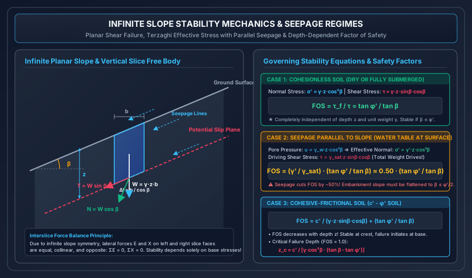
Geometric & Equilibrium Fundamentals:
- Volume of vertical slice: .
- Total weight of slice: .
- Base length of slice along failure plane: .
- Normal force on base: .
- Tangential driving force down the slope: .
Dividing forces by base area ():
- Total normal stress on failure plane:
- Mobilized driving shear stress along failure plane:
Case A: Completely Dry or Submerged Slope (Hydrostatic Regime)
- In a dry slope: .
- In a fully submerged slope under static water (no seepage flow): pore pressure , giving effective normal stress .
- Available shear strength:
- Mobilized driving shear stress:
Taking the ratio:
Fundamental Invariant: For a dry or submerged cohesionless slope, the factor of safety is entirely independent of depth and unit weight . The slope is unconditionally stable if , and unstable if . The angle of repose of dry cohesionless sand is identically equal to its internal friction angle .
Case B: Steady Seepage Parallel to the Slope (Water Table at Ground Surface)
When heavy rainfall causes steady groundwater seepage flowing parallel to the slope face, and the phreatic surface coincides with the ground surface:
- Flow lines are parallel to the slope face inclined at .
- Equipotential lines are perpendicular to the slope face.
- Hydraulic gradient: .
- Pore water pressure at depth :
- Total normal stress on slip plane:
- Effective normal stress on slip plane:
- Available shear strength:
- Mobilized driving shear stress: Because gravity acts on the entire water-soil mass, the total saturated unit weight drives the downslope sliding force:
Formulating the factor of safety:
Critical Design Takeaway: Since for typical soils (), steady seepage parallel to the face cuts the factor of safety of a sand slope by approximately . To prevent flow slides during monsoons, an unreinforced granular cut subjected to emergent seepage must have a slope angle of .
Case C: Seepage Parallel to Slope with Water Table at Depth Below Surface ()
When the upper soil of thickness is moist () and the lower soil of thickness is saturated () with parallel seepage:
- Total normal stress: .
- Pore water pressure: .
- Effective normal stress: .
- Driving shear stress: .
- Factor of safety:
4. Infinite Slope Analysis in Cohesive-Frictional Soils () & Critical Depth
For soils possessing both effective cohesion and internal friction :
Case A: Dry or Uniformly Moist Soil
With and :
Depth-Dependency & Mechanics of Failure:
- Unlike cohesionless soil, is strongly depth-dependent.
- At , (soil is ultra-stable at the surficial skin due to cohesion).
- As depth increases, the first term , causing to asymptotically approach .
- If , the slope will inevitably fail once a critical depth is reached!
Critical Depth of Failure ( or ):
Setting :
Multiplying both sides by :
For a pure clay ():
Case B: Cohesive Soil with Steady Seepage Parallel to Slope
Under full saturation with water table at the surface:
Critical failure depth under steady seepage:
5. Finite Slope Failure Mechanisms
In finite slopes, rotational shear failure dominates. The sliding mass separates from the stable ground along a curved shear surface.
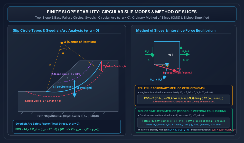
1. Classification of Rotational Failure Surfaces:
- Slope Failure (Face Failure):
- The failure surface intersects the slope face above the toe.
- Typically occurs when the slope is steep () or where a hard stratum exists directly at the toe level, preventing deeper shear arc propagation.
- Toe Failure:
- The failure surface passes precisely through the toe of the slope.
- This is the most common failure mode for slopes with moderate inclination () in homogeneous soils.
- Base Failure:
- The failure surface passes significantly below the toe, penetrating deep into the foundation soil and tangent to a firm rigid stratum.
- Occurs when the slope angle is flat () and the foundation soil below the toe is softer or has lower shear strength than the embankment fill.
Depth Factor ():
The geometry of base circles is quantified by the depth factor:
where:
- is the height of the slope.
- is the depth from the toe to the firm, impermeable stratum.
- For a toe circle: .
- For a base circle: .
6. Swedish Slip Circle Method for Pure Clay ()
The Swedish Slip Circle method (also known as the total stress analysis or Fellenius circular arc method) is the standard method for short-term undrained stability of saturated clay slopes.
Theoretical Assumptions:
- The potential slip surface is a circular cylindrical arc of radius centered at .
- The soil behaves in an undrained manner with friction angle and constant undrained shear strength .
- The sliding mass acts as a rigid body rotating about center .
Mathematical Formulation:
- Arc length of slip circle: (where is the central subtended angle in radians).
- Resisting shear force along arc: .
- Resisting moment about rotation center :
- Driving (overturning) moment about : where is the total weight of the sliding mass of cross-sectional area (), and is the horizontal lever arm from to the center of gravity of the sliding mass.
The factor of safety is the ratio of resisting to driving moments:
Tension Crack Mechanics & Water Thrust:
In cohesive soils, tension cracks develop near the crest to a theoretical depth:
The presence of a tension crack modifies the stability in two critical ways:
- Loss of Resisting Arc: Soil cannot sustain tensile stress; hence, the portion of the circular arc located within the depth contributes zero shear resistance. The subtended central angle is reduced from to , where the arc terminates at the bottom of the crack:
- Hydrostatic Water Thrust (Rainfall Condition): If heavy rains fill the crack with water to depth :
- Hydrostatic thrust: .
- This horizontal thrust acts at from the crack base, exerting an additional overturning driving moment about , where is the vertical lever arm from to the line of action of .
- The total driving moment becomes: where and represent the weight and centroid of the reduced soil mass excluding the tension crack wedge.
7. Ordinary Method of Slices (Fellenius / OMS) for Soils
When the slope consists of cohesive-frictional soil () or non-homogeneous stratified strata with pore water pressure, shear strength varies along the slip circle. The sliding mass is discretized into vertical slices.
Formulation for Slice :
- Slice width: .
- Average height: .
- Total weight: .
- Base inclination angle to horizontal: .
- Base length: .
- Pore water pressure at slice base: .
Fellenius Assumptions (OMS):
The Ordinary Method of Slices assumes that interslice forces ( and ) are parallel to the slice base and cancel each other out:
- Normal force on base: .
- Pore water force on base: .
- Effective normal force: .
- Available shear resistance along base:
- Tangential driving force along base:
Summing over all slices gives the Fellenius Factor of Safety:
Limitation of OMS: Neglecting interslice forces violates horizontal and moment equilibrium for individual slices. For deep slip circles with high pore pressures, can become artificially negative near the toe. Consequently, OMS underestimates the true factor of safety by to , providing an overly conservative design.
8. Bishop's Simplified Method of Slices
Alan W. Bishop (1955) resolved the inaccuracies of OMS by satisfying vertical force equilibrium for each slice while including horizontal interslice normal forces ().
Key Assumption:
The shear forces between adjacent slices are approximately equal ().
Vertical Equilibrium of Slice :
Resolving forces vertically:
Substituting and mobilized shear :
Noting that and solving explicitly for :
where the dimensionless geometric coefficient is defined as:
Bishop's Factor of Safety Equation:
Equating overall driving and resisting moments about the rotation center :
Characteristics of Bishop's Simplified Method:
- Iterative Nature: Because appears on both the left-hand side and within , solution requires iteration. Assuming an initial , convergence to four decimal places occurs within 2 to 3 iterations.
- High Precision: Despite neglecting interslice shear forces, extensive comparisons with rigorous limit equilibrium methods (Spencer, Morgenstern-Price) prove that Bishop's Simplified method predicts with an error of less than to .
9. Critical Stability Conditions in Earth Dams & Embankments
Under IS 7894:1975, earth dams and reservoir embankments must be evaluated for three distinct, governing operational phases:
┌───────────────────────────────────────────────────────────────────────────────────────┐
│                    CRITICAL OPERATIONAL PHASES IN EARTH DAMS                          │
├──────────────────────────┬─────────────────────────────┬──────────────────────────────┤
│ Operational Phase        │ Critical Slope Analyzed     │ Governing Stress Regime      │
├──────────────────────────┼─────────────────────────────┼──────────────────────────────┤
│ 1. End of Construction   │ Both Upstream & Downstream  │ Total Stress (Undrained,     │
│                          │ Slopes                      │ Excess Pore Pressure Δu > 0) │
├──────────────────────────┼─────────────────────────────┼──────────────────────────────┤
│ 2. Steady Seepage        │ Downstream Slope Critical   │ Effective Stress (Drained,   │
│    (Full Reservoir)      │ (Phreatic Line Emerges)     │ Flow Net Pore Pressures)     │
├──────────────────────────┼─────────────────────────────┼──────────────────────────────┤
│ 3. Sudden Drawdown       │ Upstream Slope Critical     │ Effective / Undrained Surge  │
│    (Rapid Reservoir Drop)│ (Water Support Removed)     │ (High u remains trapped)     │
└──────────────────────────┴─────────────────────────────┴──────────────────────────────┘
1. End of Construction:
- Construction of a large dam involves rapid compaction of cohesive fill.
- Low permeability prevents immediate dissipation of pore water; high excess pore pressures develop.
- Analysis: Performed using total stress parameters () or effective stress with estimated pore pressure ratio . Minimum required .
2. Steady Seepage (Reservoir Full):
- Reservoir has been at full supply level (FSL) for sufficient time to establish a steady-state phreatic surface.
- Upstream slope is stabilized by the hydrostatic reservoir water pool.
- Downstream slope is critical due to horizontal seepage forces acting outward and upward, increasing driving shear and reducing effective normal stress.
- Analysis: Effective stress parameters () with pore pressures obtained directly from flow net equipotential lines. Minimum required .
3. Sudden (Rapid) Drawdown:
- Reservoir water level drops rapidly (e.g., during emergency discharge or power generation).
- Upstream slope soil remains fully saturated because clay/silt drains orders of magnitude slower than the reservoir water drops.
- Upstream slope is critical:
- The stabilizing hydrostatic water pressure on the slope face is abruptly removed.
- Trapped internal pore water pressures remain exceptionally high.
- Seepage flow reverses direction, flowing outward toward the reservoir.
- Analysis: Effective stress with steady seepage from drawdown flow net, or modified total stress. Minimum required .
10. Taylor's Stability Number () & Chart Formulation
Donald W. Taylor (1937) established that for a homogeneous slope of height and angle in a soil, the required cohesive resistance to prevent failure can be expressed as a dimensionless ratio termed Taylor's Stability Number ():
where:
- is the mobilized cohesion required for equilibrium.
- is the factor of safety with respect to cohesion.
- is the actual height of the slope.
- is the unit weight of the soil.
Critical Height () & Height Factor of Safety ():
If cohesion is fully mobilized (), the slope can stand to a maximum critical height :
The factor of safety with respect to height is:
Special Values & Engineering Rules for :
- Pure Cohesive Soil ():
- For a vertical cut (): .
- For : .
- For : .
- Maximum theoretical stability number for base failure in soft clay with hard layer at infinity (): (for ).
- Submerged Slopes:
- In a fully submerged slope under static water, replace with the submerged unit weight :
- Sudden Drawdown Formulation:
- For sudden drawdown in cohesive-frictional soils, the pore pressure remaining trapped inside the embankment acts as an effective surcharge. Taylor derived the modified stability number :
- Because , sudden drawdown substantially increases the required stability number, drastically reducing safety.
11. Solved Numerical Problems
Problem 1: Infinite Slope Stability Across Dry, Submerged, and Seepage Regimes
Statement: A continuous natural hillside cut in cohesionless sand is inclined at . Geotechnical laboratory testing on undisturbed samples yielded:
- Effective internal friction angle:
- Dry unit weight:
- Saturated unit weight:
- Water unit weight:
(a) Determine the Factor of Safety () when the slope is completely dry.
(b) Determine the when the hillside is completely submerged under static flood water.
(c) Determine the during a prolonged torrential monsoon that induces steady groundwater seepage parallel to the slope face with the water table at the ground surface.
(d) In a second location, the slope has , , but possesses cohesion and . Under steady parallel seepage with water table at the surface, determine the critical depth where failure initiates (), and find the at depth .
Solution:
(a) Dry Slope Analysis: For a dry cohesionless slope ():
(b) Submerged Slope Analysis: For static submergence without seepage:
(c) Steady Seepage Parallel to Slope Analysis: Under parallel steady seepage with water table at ground level:
Interpretation: The slope transforms from stable () in dry conditions to actively failing () upon saturation and emergent seepage!
(d) Cohesive-Frictional Soil under Steady Seepage: Given: , , , , .
The governing factor of safety equation under seepage is:
At critical depth , :
Evaluating trigonometric functions:
Evaluating at ():
Problem 2: Swedish Slip Circle Analysis with Dry vs. Water-Filled Tension Cracks
Statement: A railway cutting of depth is excavated in a saturated homogeneous clay stratum having unit weight and undrained shear strength ().
A trial circular slip surface is analyzed:
- Radius of rotation:
- Subtended central angle (uncracked):
- Cross-sectional area of potential failure wedge:
- Center of gravity is located horizontally at from the vertical axis passing through rotation center .
(a) Calculate the Factor of Safety neglecting tension crack formation.
(b) A tension crack of theoretical depth forms at the crest. If the crack remains completely dry, the central subtended arc angle reduces to , the sliding mass area reduces to , and its centroid shifts to . Compute the modified .
(c) Following a cloudburst, the tension crack fills with rainwater to its entire depth. Given that the vertical lever arm of the resultant water thrust about center is , calculate the new and determine the percentage reduction in stability caused by the rainwater surge.
Solution:
(a) Analysis Neglecting Tension Crack:
- Weight of sliding mass per meter width:
- Driving overturning moment about center :
- Resisting moment developed by undrained shear along circular arc:
- Factor of Safety:
(b) Analysis with Dry Tension Crack:
- Theoretical depth of tension crack:
- Weight of reduced sliding mass:
- Driving moment:
- Resisting moment along reduced arc:
- Factor of Safety:
(c) Analysis with Water-Filled Tension Crack:
- Resultant horizontal hydrostatic water thrust acting inside the crack:
- Overturning moment exerted by water thrust about :
- Total driving moment:
- Resisting moment remains .
- Factor of Safety:
Problem 3: Taylor's Stability Number & Ordinary Method of Slices (OMS)
Statement: An embankment slope of height is designed with an inclination of . The soil properties are:
- Cohesion:
- Internal friction:
- Saturated unit weight:
- Bulk unit weight:
- Submerged unit weight:
(a) For and , Taylor's chart gives stability number . Determine the Factor of Safety with respect to cohesion () assuming friction is fully mobilized, and calculate the critical height .
(b) If the reservoir undergoes rapid/sudden drawdown, calculate the revised factor of safety using Taylor's modified stability number.
(c) For an alternative non-homogeneous slice geometry, the critical trial circle is discretized into 4 vertical slices. The soil shear parameters along the slip base are and (). The slice data is given in the table below:
| Slice | Width (m) | Base Inclination (deg) | Total Weight (kN/m) | Pore Pressure (kPa) | Base Length (m) |
|---|---|---|---|---|---|
| 1 | 2.5 | 240.0 | 12.0 | 2.556 | |
| 2 | 3.0 | 390.0 | 22.0 | 3.338 | |
| 3 | 3.0 | 420.0 | 18.0 | 3.807 | |
| 4 | 2.5 | 210.0 | 0.0 | 4.061 |
Calculate the overall Factor of Safety of the slope using the Ordinary Method of Slices (Fellenius / OMS).
Solution:
(a) Taylor's Stability Analysis: Given: , , , .
- Mobilized cohesion required:
- Factor of Safety with respect to cohesion:
- Critical Height :
(b) Sudden Drawdown Analysis: During sudden drawdown, internal pore pressure remains high while external pool support vanishes.
- Modified stability number:
- Factor of safety during sudden drawdown:
Critical Safety Assessment: , indicating that sudden drawdown will trigger catastrophic upstream slope failure unless the slope is flattened to or protected with free-draining rockfill riprap!
(c) Ordinary Method of Slices (OMS) Computation: For each slice :
- Driving force:
- Base normal force:
- Base pore water force:
- Effective normal force:
- Resisting shear force:
Tabulating slice by slice:
-
Slice 1: ()
- Driving force:
-
Slice 2: ()
- Driving force:
-
Slice 3: ()
- Driving force:
-
Slice 4: ()
- Driving force:
Summations:
- Total driving force:
- Total resisting shear resistance:
Overall Factor of Safety:
12. Comparative Engineering Analysis Across Syllabi
┌────────────────────────────────────────────────────────────────────────────────────────────────────────┐
│                        SYLLABUS EMPHASIS & EXAMINATION FOCUS MATRIX                            │
├─────────────┬─────────────────────────────────────────────────┬────────────────────────────────────────┤
│ Examination │ High-Yield Core Focus Areas                     │ Typical Question Typology              │
├─────────────┼─────────────────────────────────────────────────┼────────────────────────────────────────┤
│ GATE CE     │ • Infinite slopes: dry vs submerged vs seepage  │ 1-2 mark MCQs/NATs on ratio            │
│             │ • Critical depth z_c for c-φ infinite slopes    │ γ'/γ_sat = 0.5; Taylor stability       │
│             │ • Taylor's Sn formulas & sudden drawdown factor │ number calculations; Bishop m_α        │
├─────────────┼─────────────────────────────────────────────────┼────────────────────────────────────────┤
│ UPSC ESE    │ • Swedish circle derivations (φ_u = 0) with     │ 10-20 mark conventional proofs of      │
│             │   tension cracks and water thrust M_w           │ Bishop vertical equilibrium; full      │
│             │ • Earth dam critical phases (IS 7894)           │ tabular method of slices problems      │
├─────────────┼─────────────────────────────────────────────────┼────────────────────────────────────────┤
│ SSC JE &    │ • Angle of repose = internal friction φ'        │ Rapid objective MCQs on failure        │
│ RRB JE      │ • Infinite slope seepage cuts FOS by 50%        │ circle types (toe vs base), D_f > 1,   │
│             │ • Depth factor D_f = (H+D)/H classification     │ vertical cut H_c = 4c/γ                │
├─────────────┼─────────────────────────────────────────────────┼────────────────────────────────────────┤
│ State AE/JE │ • Taylor's Sn = c / (Fc · γ · H) calculations   │ Direct formula substitutions,          │
│             │ • End of construction vs drawdown conditions    │ definitions of mobilized cohesion c_m  │
└─────────────┴─────────────────────────────────────────────────┴────────────────────────────────────────┘
13. Common Misconceptions & Examination Pitfalls
-
Submerged vs. Seepage Invariant:
- Trap: Assuming that a fully submerged slope has a reduced factor of safety compared to a dry slope.
- Reality: For static water (no flow), . The buoyant reduction applies equally to both resisting friction () and driving shear (), leaving the ratio unchanged. Only seepage flow (gradient ) reduces the factor of safety!
-
Total vs. Submerged Unit Weight in Seepage Driving Stress:
- Trap: Using submerged unit weight to calculate the driving shear stress during steady seepage.
- Reality: In steady seepage, gravity acts on the total mass (soil + pore water). Hence, the driving shear stress is , while effective normal stress is . This asymmetry is precisely why is reduced by .
-
Depth Factor Definition:
- Trap: Defining .
- Reality: By international standard, . Thus, represents a toe circle; represents a base circle.
-
Tension Crack Hydrostatic Lever Arm:
- Trap: Taking the lever arm of the water thrust from the base of the crack rather than about the center of rotation .
- Reality: In moment equilibrium, moments must be taken strictly about the center of rotation . If has vertical coordinate and the crest is at , the line of action of is at , giving vertical lever arm .
-
Taylor's Stability Number during Sudden Drawdown:
- Trap: Using the dry/bulk unit weight in during drawdown.
- Reality: During sudden drawdown, the effective stability number is . The denominator must utilize .