Rapidly Varied Flow (RVF): Hydraulic Jump Momentum, Sequent Depths, Energy Dissipation & Stilling Basins
In this chapter (4 topics)
On this page
- 1. Module Scope & Pedagogical Objectives
- 2. Comprehensive Syllabus Mapping
- 3. Physical Principles, Flow Regimes & Engineering Assumptions
- 3.1 Physical Nature of the Hydraulic Jump
- 3.2 Key Terminology: Sequent Depths vs Alternate Depths
- 3.3 Governing Assumptions for Ideal Horizontal Jump
- 4. Rigorous Mathematical Formulations & Analytical Derivations
- 4.1 Proof 1: Linear Momentum Equation & Conservation of Specific Force
- 4.2 Proof 2: Belanger’s Equation for Sequent (Conjugate) Depths
- 4.3 Proof 3: Exact Derivation of Energy Head Loss (Δ E)
- 4.4 Proof 4: Jump Characteristics (Height, Efficiency, Power & Length)
- 4.5 Proof 5: Hydraulic Jump in Non-Rectangular Channels
- 4.6 Proof 6: Mechanics of Stilling Basins & Baffle Pier Drag Force
- 5. Hand-Coded High-Precision Engineering Visualizations
- 5.1 Diagram 1: Hydraulic Jump Momentum Balance & Sequent Depths
- 5.2 Diagram 2: USBR Hydraulic Jump Classification & Stilling Basin Design
- 6. Comparative Engineering Analysis & Cross-Sectional Synthesis
- 6.1 USBR Hydraulic Jump Classification Matrix
- 6.2 Stilling Basin Typology Comparison (USBR Standards)
- 7. Fully Worked Numerical Problems (Pre-Calculated & Verified)
- Problem 1: Sequent Depths, Energy Loss, Length & Power in a Rectangular Spillway Apron
- Problem 2: Stilling Basin with Baffle Piers & Tailwater Control
- Problem 3: Hydraulic Jump in a Non-Rectangular (Triangular) Channel
- 8. Critical Exam Traps, Failure Modes & Conceptual Pitfalls
- 9. Real-World Engineering Case Studies & Forensic Failures
- 9.1 Oroville Dam Spillway Chute Failure (California, USA, 2017)
- 9.2 Stilling Basin Cavitation at Tarbela Dam (Pakistan)
- 10. Cross-Disciplinary & Downstream Dependencies
- 11. High-Yield Revision Formula Cheat Sheet
- 12. Authoritative References & Standards
1. Module Scope & Pedagogical Objectives
Rapidly Varied Flow (RVF) represents an extreme hydrodynamic phenomenon in open channel systems where the flow velocity, water surface curvature, and depth change dramatically over an exceedingly short longitudinal distance. Unlike Gradually Varied Flow (GVF), where streamlines remain essentially parallel and hydrostatic pressure distribution holds, RVF is governed by severe streamline curvature, profound non-hydrostatic internal pressure distributions, intense turbulent shear layers, macroscopic recirculating vortices, and extensive air entrainment.
The premier engineering manifestation of RVF is the Hydraulic Jump—a stationary, turbulent surge formed when a high-velocity, supercritical shooting stream () abruptly decelerates and transitions into a low-velocity, subcritical tranquil stream (). Because a hydraulic jump dissipates tremendous kinetic energy into thermal turbulence without mechanical equipment, it is universally harnessed at the foot of spillways, sluice gates, and drop structures to prevent catastrophic downstream riverbed scour.
       Supercritical Shooting Jet (Fr₁ > 1)        Turbulent Roller & Energy Dissipation          Subcritical Flow (Fr₂ < 1)
   ═════════════════════════════════════════════► [███████████████████████████████████████] ════════════════════════════════►
   Low Depth y₁ (High Kinetic Head V₁²/2g)        Momentum Conserved (F₁ = F₂); Head Loss ΔE       High Depth y₂ (Low Kinetic Head)
The core pedagogical objectives of this module are:
- Establish the physical mechanics of the hydraulic jump, distinguishing between internal energy dissipation and linear momentum conservation across the jump.
- Mathematically derive the governing momentum equation in horizontal rectangular channels and formulate Belanger’s exact relationships for sequent (conjugate) depths.
- Deduce the exact analytical formulation for energy head loss () and quantify jump efficiency, relative jump height, and jump length.
- Classify hydraulic jumps according to the upstream Froude number () based on the United States Bureau of Reclamation (USBR) criteria.
- Formulate the hydrodynamic design principles of hydraulic energy dissipators, including USBR Types I, II, III, and IV stilling basins, and quantify the drag forces exerted by chute blocks and baffle piers.
- Extend hydraulic jump analysis to non-rectangular prismatic geometries (triangular, trapezoidal, circular) through the universal principle of Specific Force equivalence ().
2. Comprehensive Syllabus Mapping
This module directly addresses the open channel flow requirements of premier national competitive and licensing examinations:
| Examination Body | Specific Syllabus Topics Addressed | Typical Question Pattern |
|---|---|---|
| GATE CE | Rapidly varied flow, hydraulic jump in rectangular and non-rectangular channels, conjugate/sequent depths, energy loss, specific force, jump classification. | 1-mark objective questions on jump type and Belanger equation; 2-mark numericals on sequent depths, energy loss , and non-rectangular jump root-finding. |
| UPSC ESE (Civil) | Rapidly varied flow, momentum equation applied to hydraulic jump, Belanger's equations, energy dissipation, stilling basins and appurtenances (chute blocks, baffle piers, end sills). | Conventional 10–20 mark derivations of Belanger equation and stilling basin design; multiple-choice questions on USBR basin typology and Froude classification. |
| SSC JE / State AE | Definition of hydraulic jump, conjugate depths, loss of head in a jump, height and length of jump, types of jumps, practical uses of hydraulic jump. | Formula identification (, ), direct single-step numerical computations, conceptual questions on Froude ranges (). |
| RRB JE | Open channel hydraulics, hydraulic jump, energy dissipators, stilling basins, prevention of erosion below spillways. | Straightforward formula recall, definitions of sequent depths vs alternate depths, empirical jump lengths. |
3. Physical Principles, Flow Regimes & Engineering Assumptions
3.1 Physical Nature of the Hydraulic Jump
When liquid flows in an open channel at a speed greater than the celerity of an elementary gravity wave (), the flow is supercritical (). Such a stream cannot receive upstream pressure signals from downstream controls. If downstream conditions (such as a channel obstruction, weir, or tailwater level) demand a subcritical flow state (), the flow cannot transition smoothly through critical depth without an external boundary constriction (like a hump). Instead, the flow undergoes a violent, self-adjusting hydraulic shock—the hydraulic jump.
Within the jump body:
- Kinetic energy of the supercritical incoming jet is converted into potent internal fluid turbulence, macroscopic counter-rotating eddies (the surface roller), sound, heat, and air entrainment.
- Severe boundary shear exists, but because the jump occurs over a relatively short horizontal reach (), the cumulative boundary friction force is minute compared to the massive hydrostatic pressure and dynamic momentum flux forces.
- Consequently, while total mechanical energy decreases dramatically (), the Specific Force (linear momentum plus hydrostatic thrust) is conserved ().
3.2 Key Terminology: Sequent Depths vs Alternate Depths
A fundamental distinction in open channel hydraulics that is frequently tested in competitive examinations is the difference between Alternate Depths and Sequent (Conjugate) Depths:
   ┌───────────────────────────────────────────────┬───────────────────────────────────────────────┐
   │             ALTERNATE DEPTHS                  │           SEQUENT (CONJUGATE) DEPTHS          │
   ├───────────────────────────────────────────────┼───────────────────────────────────────────────┤
   │ Depths having identical SPECIFIC ENERGY (E).  │ Depths having identical SPECIFIC FORCE (F).   │
   │ E₁ = E₂ (Zero energy loss: ΔE = 0).           │ F₁ = F₂ (Finite turbulent energy loss: ΔE > 0)│
   │ Reversible theoretical states.                │ Irreversible physical states before/after jump│
   │ Linked across frictionless humps/transitions. │ Linked across a hydraulic jump.               │
   │ y₁ < yc < y₂.                                 │ y₁ < yc < y₂.                                 │
   └───────────────────────────────────────────────┴───────────────────────────────────────────────┘
3.3 Governing Assumptions for Ideal Horizontal Jump
To formulate analytical relationships for a hydraulic jump, the following classic engineering assumptions (Belanger, 1838) are enforced:
- Horizontal and Prismatic Channel: The channel bed slope is approximately horizontal (), meaning the component of fluid weight in the direction of motion is negligible ().
- Negligible Boundary Friction: Because the longitudinal length of the jump is very short, the total boundary shear resistance .
- Hydrostatic Pressure Distribution at Sections 1 and 2: Sections 1 (immediately upstream) and 2 (immediately downstream) are chosen just outside the intense curved-roller zone where streamlines are virtually straight and parallel. Hence, pressure distributions at 1 and 2 are purely hydrostatic.
- Uniform Velocity Distribution (): Momentum correction factors at the entry and exit sections are assumed to be unity.
- Incompressible, Single-Phase Inflow: Water is treated as incompressible with constant mass density and unit weight .
4. Rigorous Mathematical Formulations & Analytical Derivations
4.1 Proof 1: Linear Momentum Equation & Conservation of Specific Force
Consider a control volume of fluid in a horizontal, rectangular channel of width bounded by Section 1 (depth , velocity ) and Section 2 (depth , velocity ).
                     Control Volume Across a Hydraulic Jump

            ◄── Section 1 (Toe)              Section 2 (Tailwater) ──►
               ┌─────────────────────────────────────────────────────┐
         y₁    │ ~ ~ ~ ~ ~ ~ ~ ~ ~ \ \ \ \ \ ~ ~ ~ ~ ~ ~ ~ ~ ~ ~ ~ ~ │ y₂
        ───────┤══════►             \ \ \ \ \                        ├───────
               │  V₁                (Roller)             ════►       │
        P₁ ───►│                                          V₂    ◄─── │ P₂
               │                                                     │
               └─────────────────────────────────────────────────────┘
               ▲──────────────────────── Lj ─────────────────────────▲
                                 Channel Bed (S₀ = 0)
Applying Newton's Second Law in the horizontal direction:
The external forces acting on the control volume in the -direction are:
- Upstream hydrostatic pressure force: .
- Downstream hydrostatic pressure force: .
- Total boundary shear force: .
- Gravity component along bed: (horizontal channel).
Substituting into the linear momentum balance:
Dividing both sides by , noting that is the discharge per unit width:
Since by continuity and :
Rearranging all terms associated with state 1 to the left and state 2 to the right:
Multiplying through by channel width :
4.2 Proof 2: Belanger’s Equation for Sequent (Conjugate) Depths
Returning to the algebraic relation:
Factoring the left-hand side as :
Since for a true hydraulic jump (), we divide both sides by :
Multiplying both sides by :
Dividing the entire equation by :
Recognizing that the upstream Froude number is:
Substituting into the quadratic equation:
Solving this quadratic equation for the depth ratio using the quadratic formula:
Since physical water depth must be positive (), we reject the negative root:
By exact symmetry, if the jump is viewed in reverse or expressed in terms of downstream Froude number :
Product of Sequent Depths:
From the intermediate step :
This is an indispensable formula in exam problems where critical depth must be calculated directly from given conjugate depths and .
4.3 Proof 3: Exact Derivation of Energy Head Loss ()
The specific energy at any section in a rectangular channel is:
The energy head loss across the jump is:
Factor out :
From the momentum balance in Proof 2, recall that:
Substitute this value of into the energy loss bracket:
Substitute this back into the expression for :
Physical Significance of the Proof:
- Since for any jump, , confirming that is strictly positive: mechanical energy is always dissipated, satisfying the Second Law of Thermodynamics.
- An "expansion jump" from subcritical to supercritical () would yield (spontaneous energy generation), which is physically impossible in nature.
4.4 Proof 4: Jump Characteristics (Height, Efficiency, Power & Length)
1. Height of the Jump ():
2. Hydraulic Jump Efficiency ():
The efficiency of a hydraulic jump is defined as the fraction of mechanical energy remaining after the jump:
In terms of the upstream Froude number , it can be rigorously simplified to:
3. Power Dissipated by the Jump ():
The total rate of mechanical energy converted into turbulent kinetic energy and heat across the width :
4. Length of the Jump ():
The length of a hydraulic jump cannot be determined purely from one-dimensional theoretical momentum equations because internal turbulent mixing and roller reattachment are three-dimensional viscous phenomena. Extensive empirical experiments by the USBR, Ven Te Chow, and K. Subramanya have established that:
- For rectangular channels with :
- In terms of sequent depth , for well-formed jumps ():
- Length of the surface roller ():
4.5 Proof 5: Hydraulic Jump in Non-Rectangular Channels
For any non-rectangular prismatic cross section (triangular, trapezoidal, circular, parabolic), the general momentum balance remains valid:
Where is the cross-sectional area, and is the vertical depth from the free surface to the centroid of the flow area.
Symmetrical Triangular Channel:
For a triangular section with side slope ():
- Area:
- Centroid depth:
- First moment of area:
The specific force equation becomes:
Equating :
Multiplying through by and rearranging:
Factoring :
Dividing by :
Dividing the entire equation by and substituting :
Recognizing the upstream Froude number for a triangular channel where hydraulic depth :
Substituting into the algebraic equation:
4.6 Proof 6: Mechanics of Stilling Basins & Baffle Pier Drag Force
In many practical dam and spillway installations, the natural tailwater depth provided by the river downstream is smaller than the required sequent depth (). Under this condition, an unassisted hydraulic jump will be swept out of the concrete apron and pushed into the unprotected downstream earthen channel, causing destructive riverbed erosion.
To force and stabilize the jump within a shortened concrete apron, stilling basin appurtenances are installed:
- Chute Blocks: Corrugated serrated blocks at the entrance to break the incoming supercritical sheet into separate high-speed jets.
- Baffle Piers (Impact Baffles): Intermediate vertical concrete blocks that directly absorb dynamic fluid impact and exert a concentrated drag force opposing flow.
- End Sill: A solid or dentated sill at the downstream edge that creates a protective ground roller to deposit scoured sediment against the apron rather than washing it downstream.
              Control Volume with Baffle Pier Drag Force

            ◄── Section 1 (Toe)                   Section 2' (Tailwater) ──►
               ┌────────────────────────────────────────────────────────────┐
         y₁    │                                     Baffle Pier            │ y₂' < y₂
        ───────┤══════►                             ┌────┐                  ├──────────
               │  V₁                                │ FD │◄── Drag Force    │  V₂'
        P₁ ───►│                                    └────┘                  │ ◄─── P₂'
               │                                                            │
               └────────────────────────────────────────────────────────────┘
               ▲──────────────────────── L_basin ───────────────────────────▲
Applying the momentum equation including the total horizontal drag force exerted by the baffle blocks on the fluid:
Rearranging to solve for the total drag force required to stabilize the jump at restricted depth :
For a rectangular channel of width :
In terms of Specific Force per unit width:
Key Design Benefit: By generating drag force , the baffle piers satisfy momentum equilibrium with a smaller tailwater depth , and reduce the required basin length by to , saving immense quantities of structural concrete.
5. Hand-Coded High-Precision Engineering Visualizations
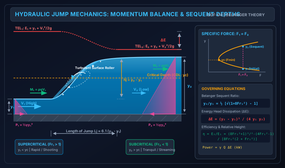
5.1 Diagram 1: Hydraulic Jump Momentum Balance & Sequent Depths
The following SVG schematic details the complete internal hydrodynamic structure of the hydraulic jump, illustrating the incoming supercritical jet, turbulent roller, air entrainment, hydrostatic pressure wedges, momentum flux vectors, and the corresponding Specific Force () curve.
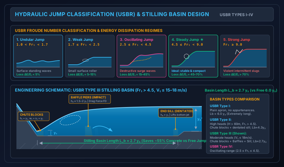
5.2 Diagram 2: USBR Hydraulic Jump Classification & Stilling Basin Design
The following SVG schematic classifies the 5 USBR hydraulic jump regimes based on upstream Froude number , and provides the detailed engineering architecture of a USBR Type III stilling basin with chute blocks, baffle piers, and dentated end sill.
6. Comparative Engineering Analysis & Cross-Sectional Synthesis
6.1 USBR Hydraulic Jump Classification Matrix
| Jump Classification | Upstream Froude Range () | Surface Characteristics & Flow Physics | Energy Head Loss () | Practical Engineering Action / Stilling Basin |
|---|---|---|---|---|
| Undular Jump | Water surface exhibits small periodic standing waves; no true turbulent roller formed. Velocity remains nearly uniform. | No energy dissipator required; channel lining extended slightly to prevent wave sloshing. | ||
| Weak Jump | Small surface rollers develop; water surface downstream is smooth and level. Flow velocity is quite uniform. | Simple concrete apron (USBR Type I); basin length . | ||
| Oscillating Jump | Unstable, pulsating jet: Jet enters and oscillates intermittently from channel bed to free surface. Creates large destructive standing waves traveling kilometers downstream. | Critical Failure Zone: Standard stilling basins fail. Requires USBR Type IV basin with large deflector sills or wave suppressors. Avoid this range if possible. | ||
| Steady Jump | True, well-balanced hydraulic jump: Surface roller and jump position are completely stable and locked in place. Extreme energy dissipation with quiet, tranquil downstream outflow. | Ideal Operating Range: USBR Type III basin (for ) with chute blocks and baffle piers; or USBR Type II (for high heads). | ||
| Strong / Choppy Jump | Violent, rough, highly aerated jump. High-velocity core intermittently breaks through roller, throwing upward slugs of water and spray. | Deep USBR Type II basin; requires thick reinforced concrete floor slabs and post-tensioned anchors to resist uplift. |
6.2 Stilling Basin Typology Comparison (USBR Standards)
| Basin Type | Applicable Froude Range () | Inflow Velocity / Head Limits | Basin Appurtenances Included | Basin Length () | Typical Applications |
|---|---|---|---|---|---|
| USBR Type I | All (plain) | Low velocity | None (plain flat concrete apron) | Minor irrigation canals, low-drop structures where land/concrete cost is secondary. | |
| USBR Type II | High-head dams (); | Chute blocks at toe + Dentated end sill (NO baffle piers to avoid cavitation) | Large concrete gravity dam spillways (e.g., Bhakra, Hoover Dam). | ||
| USBR Type III | Moderate heads (); | Chute blocks + Baffle piers + Dentated/solid end sill | Medium-head spillways, canal barrages, outlet works. Saves length. | ||
| USBR Type IV | Oscillating jump range | Special oversized chute blocks + solid end sill | Canal drops, diversion weirs where discharge fluctuations force operation in oscillating zone. |
7. Fully Worked Numerical Problems (Pre-Calculated & Verified)
Problem 1: Sequent Depths, Energy Loss, Length & Power in a Rectangular Spillway Apron
Statement: A rectangular concrete spillway apron of width discharges water at a constant rate of . The depth of supercritical flow at the toe of the spillway is measured as . Assuming a horizontal frictionless channel apron and taking and water density :
- Calculate the upstream velocity and upstream Froude number .
- Classify the type of hydraulic jump formed according to USBR criteria.
- Compute the conjugate (sequent) depth , downstream velocity , and downstream Froude number .
- Determine the jump height and the total length of the jump using the standard USBR multiplier ().
- Compute the energy head loss across the jump using both specific energy differences and Belanger’s analytical formula.
- Determine the relative energy dissipation percentage and the hydraulic jump efficiency .
- Calculate the total continuous power dissipated by the jump in kilowatts (kW).
Step-by-Step Solution:
Step 1: Upstream Flow Parameters
Unit discharge:
Upstream velocity:
Upstream Froude number:
Step 2: USBR Jump Classification
Since falls strictly within the range , this jump is classified as a Steady Hydraulic Jump. The jump is well-balanced, stable, insensitive to slight tailwater variations, and provides excellent energy dissipation.
Step 3: Sequent Depth & Downstream Flow Parameters
Applying Belanger’s exact equation:
Downstream velocity:
Downstream Froude number:
Step 4: Jump Geometry (Height & Length)
Jump height:
Jump length:
Step 5: Energy Head Loss Across Jump
Using Belanger’s formula:
Verification via Specific Energy:
Step 6: Relative Dissipation & Jump Efficiency
Relative head loss:
Jump efficiency:
Step 7: Power Dissipated
Problem 2: Stilling Basin with Baffle Piers & Tailwater Control
Statement: A rectangular stilling basin of width is located downstream of a sluice gate carrying a discharge of (). The supercritical depth at the entrance is . Due to riverbed topography downstream, the available tailwater depth is restricted to .
- Compute the free, unassisted sequent depth required for a natural hydraulic jump. Explain what happens if no baffle piers are provided.
- In order to stabilize the jump inside the basin at the available tailwater depth , a row of reinforced concrete baffle piers is installed on the apron floor. Calculate the total horizontal drag force (in kN) that must be exerted by the baffle piers on the flowing water.
- Compute the energy head loss and power dissipated in the baffled stilling basin.
Step-by-Step Solution:
Step 1: Natural Sequent Depth Check
Upstream velocity:
Upstream Froude number:
Natural conjugate depth without baffles:
Physical Finding: The natural sequent depth is significantly greater than the available downstream tailwater depth (). Without artificial resistance, the hydrostatic pressure downstream () is insufficient to arrest the incoming momentum . The jump will be completely swept out (repelled) from the basin into the downstream unprotected canal, causing severe bed degradation.
Step 2: Total Drag Force Exerted by Baffle Piers
At the exit of the baffled basin with :
Hydrostatic pressure forces:
Momentum fluxes:
Applying the Momentum equation:
Verification via Specific Force Difference:
Step 3: Energy Head Loss & Power Dissipated in Baffled Basin
Power dissipated:
Problem 3: Hydraulic Jump in a Non-Rectangular (Triangular) Channel
Statement: A symmetrical triangular channel has side slopes of (, included vertex angle ). It carries a flow of . A hydraulic jump occurs in the channel where the initial supercritical depth is . Taking :
- Determine the upstream flow area , top width , hydraulic depth , and upstream Froude number .
- Formulate the Specific Force equation for this triangular channel and evaluate .
- Compute the sequent depth following the jump by solving the momentum equilibrium .
- Calculate the energy head loss , relative energy dissipation, and jump efficiency.
Step-by-Step Solution:
Step 1: Upstream Geometric and Flow Parameters
For a triangular section with :
- Area:
- Top width:
- Hydraulic depth:
- Upstream velocity:
Upstream Froude number:
(Flow is intensely supercritical, ).
Step 2: Specific Force Formulation
For a triangular channel, the centroid of the area lies at depth below the surface:
Specific Force function:
Evaluating upstream specific force at :
Step 3: Determining Sequent Depth
Across the jump, :
Let :
- Try :
- Try :
Using linear interpolation / Newton-Raphson:
Check:
Downstream properties:
- (Tranquil subcritical flow confirmed).
Step 4: Energy Head Loss & Efficiency
Relative energy loss:
Efficiency:
8. Critical Exam Traps, Failure Modes & Conceptual Pitfalls
   ┌───────────────────────────────────────────────┬───────────────────────────────────────────────┐
   │             EXAM TRAP / MISCONCEPTION         │            RIGOROUS SCIENTIFIC REALITY        │
   ├───────────────────────────────────────────────┼───────────────────────────────────────────────┤
   │ 1. Applying Belanger's equation to non-       │ TRAP: Belanger's y₂/y₁ equation is strictly   │
   │    rectangular cross sections.                │ valid ONLY for rectangular channels! For      │
   │                                               │ triangular or trapezoidal channels, you must  │
   │                                               │ solve F₁ = F₂ using A·z̄.                      │
   ├───────────────────────────────────────────────┼───────────────────────────────────────────────┤
   │ 2. Confusing Alternate Depths with            │ Alternate depths have E₁ = E₂ (zero loss).    │
   │    Sequent (Conjugate) Depths.                │ Sequent depths have F₁ = F₂ (finite loss ΔE). │
   │                                               │ Both have y₁ < yc < y₂, but y₂_alt ≠ y₂_seq! │
   ├───────────────────────────────────────────────┼───────────────────────────────────────────────┤
   │ 3. Using Belanger's energy loss formula       │ ΔE = (y₂ - y₁)³/(4 y₁ y₂) is valid ONLY for   │
   │    ΔE = (y₂ - y₁)³/(4 y₁ y₂) for triangular   │ rectangular channels. For other shapes, you   │
   │    or trapezoidal channels.                   │ must compute ΔE = E₁ - E₂ directly.          │
   ├───────────────────────────────────────────────┼───────────────────────────────────────────────┤
   │ 4. Forgetting that Fr₁ must be calculated     │ For non-rectangular channels, Fr = V/√(g D)   │
   │    using hydraulic depth D = A/T, NOT         │ where D = A/T. In triangular channels,        │
   │    depth y.                                   │ D = (my²)/(2my) = y/2, NOT y!                │
   ├───────────────────────────────────────────────┼───────────────────────────────────────────────┤
   │ 5. Assuming tailwater depth equals sequent   │ If y_tail < y₂, jump sweeps downstream.       │
   │    depth in all natural rivers.               │ If y_tail > y₂, jump is submerged (drowned).  │
   │                                               │ A free jump forms ONLY when y_tail = y₂.      │
   ├───────────────────────────────────────────────┼───────────────────────────────────────────────┤
   │ 6. Believing baffle piers are safe on high-   │ Baffle piers create intense localized suction │
   │    head dams with V₁ > 18–20 m/s.             │ cavitation and concrete erosion. USBR limits │
   │                                               │ Type III baffles to V₁ ≤ 15–18 m/s!          │
   └───────────────────────────────────────────────┴───────────────────────────────────────────────┘
9. Real-World Engineering Case Studies & Forensic Failures
9.1 Oroville Dam Spillway Chute Failure (California, USA, 2017)
- Background: In February 2017, the main concrete spillway chute of Oroville Dam was operated under extreme inflow conditions ().
- Hydrodynamic Trigger: The high-velocity supercritical sheet () exerted massive hydrodynamic uplift and stagnation pressures through cracked concrete joints. When cavitation and stagnation pressures penetrated underneath the slab, huge sections of the concrete chute were blown out, initiating severe regressive erosion that threatened the emergency spillway.
- Forensic Takeaway: High-velocity supercritical flow transitions require flawless drainage systems, waterstops, anchor tendons deep into bedrock, and precise aeration grooves to prevent destructive cavitation damage before water ever reaches the terminal energy dissipator.
9.2 Stilling Basin Cavitation at Tarbela Dam (Pakistan)
- Background: During early commissioning of the tunnel outlet works at Tarbela Dam, high-velocity water () discharged directly into stilling basins equipped with large intermediate baffle blocks.
- Hydrodynamic Mechanism: The flow velocity far exceeded the safe cavitation limit () for impact baffles. Massive low-pressure vapor cavities collapsed directly against the concrete face of the piers, gouging out massive steel-reinforced concrete blocks within hours.
- Remedial Action: The baffle piers were completely removed, converting the stilling basin into a USBR Type II design relying solely on chute blocks and a dentated end sill, with basin floor slab thickness substantially increased.
10. Cross-Disciplinary & Downstream Dependencies
                              ┌──────────────────────────────────────────────┐
                              │  FM-04: Bernoulli & Linear Momentum Theorem  │
                              └──────────────────────┬───────────────────────┘
                                                     ▼
                              ┌──────────────────────────────────────────────┐
                              │    OCF-02: Specific Energy & Critical Depth   │
                              └──────────────────────┬───────────────────────┘
                                                     ▼
                              ┌──────────────────────────────────────────────┐
                              │  OCF-04: Hydraulic Jump & Energy Dissipation │
                              │          (Belanger Theory & USBR Basins)     │
                              └──────┬────────────────────────────────┬──────┘
                                     │                                │
                                     ▼                                ▼
┌──────────────────────────────────────────────┐    ┌──────────────────────────────────────────────┐
│ IRRI-03: Spillways, Energy Dissipators &     │    │ RCC-08: Stilling Basin Apron Structural Slab │
│ Gravity Dam Apron Protection                 │    │ Design & Anti-Uplift Anchor Tendons          │
└──────────────────────────────────────────────┘    └──────────────────────────────────────────────┘
- Prerequisites:
FM-04-03: Linear momentum conservation control volume formulations and momentum correction factors.OCF-02: Specific Energy, critical flow criteria (), and Specific Force concept.
- Downstream Course Dependencies:
IRRI-03(Irrigation & Water Resources Engineering): Design of Ogee spillways, roller buckets, ski-jump buckets, and stilling basin length calculations.RCC-08/ Structural Foundation Engineering: Concrete apron thickness design to counteract subterranean hydrostatic uplift forces and anchor tendon tensioning.- River Engineering: Tailwater rating curve (TWC) vs jump rating curve (JRC) matching to determine spillway apron floor depression.
11. High-Yield Revision Formula Cheat Sheet
12. Authoritative References & Standards
- Chow, Ven Te. Open-Channel Hydraulics. McGraw-Hill Book Company, New York, 1959. (The seminal international treatise on Belanger theory, jump mechanics, and stilling basins).
- Subramanya, K. Flow in Open Channels. 5th ed., McGraw Hill Education (India), 2019. (Authoritative standard for Indian competitive exams GATE, ESE, and State AE).
- United States Bureau of Reclamation (USBR). Hydraulic Design of Stilling Basins and Energy Dissipators. Engineering Monograph No. 25, US Department of the Interior, Denver, Colorado, 1984. (The definitive engineering guide for Types I–IV stilling basins, chute blocks, and baffle piers).
- Bureau of Indian Standards (BIS):
- IS 4997: 1979 (Reaffirmed 2017): Criteria for Design of Hydraulic Jump Type Stilling Basins with Horizontal and Sloping Apron.
- IS 11527: 1985 (Reaffirmed 2019): Criteria for Structural Design of Energy Dissipators for Spillways.
- Ranga Raju, K. G. Flow Through Open Channels. 3rd ed., Tata McGraw-Hill, New Delhi, 2001.
- Henderson, F. M. Open Channel Flow. Macmillan Publishing, New York, 1966.