Kinematics & Kinetics of Particles & Rigid Bodies (D'Alembert, Work-Energy, Impulse-Momentum, Oblique Impact)
In this chapter (1 topics)
On this page
- 1. Executive Summary & Core Definitions
- Core Definitions
- 2. Foundational Principles & Governing Axioms
- 2.1 The Three Classical Approaches of Kinetics
- 2.2 Collision Mechanics (Direct Central vs Oblique Impact)
- 3. Step-by-Step Analytical Derivations
- 3.1 Derivation of Kinematic Equations for Constant Acceleration
- 3.2 Derivation of Normal Centripetal Acceleration (an = v2 / ρ)
- 3.3 Derivation of Projectile Motion Trajectory & Bounds
- 3.4 Kinetic Energy Loss During Inelastic Impact
- 3.5 Pure Rolling of a Rigid Body Down an Inclined Plane
- 4. Key Formulas & Summary Tables
- Table 4.1: Master Formulas in Engineering Dynamics
- Table 4.2: Comparison of Descending Bodies on Rough Incline (θ = 30°)
- 5. Visual Architectural Diagrams
- Diagram 1: Particle Kinematics, Curvilinear Acceleration & Projectile Motion
- Diagram 2: D'Alembert's Principle, Work-Energy, Impulse & Rigid Body Rolling
- 6. Standard Practice Guidelines & Boundary Conditions
- 6.1 Codal Provisions & Dynamic Engineering Rules
- 7. Critical Failure Modes & Edge Cases
- 7.1 Neglecting Reversed Direction in D'Alembert Inertia Forces
- 7.2 The Plastic Collision Energy Paradox
- 7.3 Rolling vs Slipping Threshold on Steep Slopes
- 8. Worked Numerical Problems
- Problem 1: Pile Driver Dynamics & Soil Dynamic Resistance Analysis
- Problem 2: Oblique Impact of Particles with Restitution
- Problem 3: The Great Incline Race: Rolling of Rigid Bodies Without Slipping
- 9. Comparative Exam Analysis
- 10. Common Pitfalls & Traps
- 11. Real-World Civil & Structural Applications
- 12. Comprehensive Summary & Quick Revision Guide
- 13. Practice Problems for Self-Assessment
- 14. References & Standard Texts
1. Executive Summary & Core Definitions
Dynamics is the branch of engineering mechanics that studies the motion of material bodies under the action of time-varying forces, divided into Kinematics (the geometric description of motion—displacement, velocity, and acceleration—without regard to the causative forces) and Kinetics (the analysis of the relationship between acting forces, mass inertia, and the resulting motion). In civil engineering, dynamic principles are foundational to driven pile installation, vehicle impact mechanics on bridge parapets, seismic wave propagation, railway track superelevation on horizontal curves, and the vibration of cable-stayed structures.
                  +-------------------------------------------------+
                  |              ENGINEERING DYNAMICS               |
                  +-----------------------+-------------------------+
                                          |
                 +------------------------+------------------------+
                 |                                                 |
                 v                                                 v
   +---------------------------+                     +---------------------------+
   |        KINEMATICS         |                     |          KINETICS         |
   | (Geometry of Motion: s,v,a)                     | (Forces & Inertial Motion)|
   +-------------+-------------+                     +-------------+-------------+
                 |                                                 |
         +-------+-------+                         +---------------+---------------+
         |               |                         |               |               |
         v               v                         v               v               v
    Rectilinear     Curvilinear               Newton /        Work-Energy       Impulse-
      Motion          Motion                 D'Alembert        Theorem          Momentum
Core Definitions
- Rectilinear Motion: Translation along a straight line where position is defined by a single scalar coordinate .
- Curvilinear Motion: Motion along a curved spatial or planar path, naturally formulated in path coordinates (tangential and normal ) or polar coordinates ().
- Radius of Curvature (): The instantaneous radius of the osculating circle tangent to a curved path:
- Tangential Acceleration (): The rate of change of the magnitude of velocity (speed):
- Normal (Centripetal) Acceleration (): The rate of change of the direction of the velocity vector, directed perpendicular to the path toward the center of curvature:
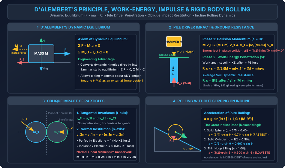
- D'Alembert's Principle: The axiom stating that a dynamic system in motion can be converted into an equivalent system in static equilibrium by adding a fictitious "reversed effective force" (inertia force, , and inertia couple, ):
- Work-Energy Theorem: The net work done by all external forces (conservative and non-conservative) on a body equals the change in its kinetic energy:
- Linear Impulse-Momentum Theorem: The time integral of resultant force equals the change in linear momentum:
- Coefficient of Restitution (): The ratio of the relative velocity of separation to the relative velocity of approach along the line of impact:
- Instantaneous Center of Zero Velocity (ICOR): A unique point in the plane of a rigid body undergoing general plane motion that has zero instantaneous linear velocity ().
2. Foundational Principles & Governing Axioms
2.1 The Three Classical Approaches of Kinetics
Every kinetic problem involving particles or rigid bodies can be analyzed via three alternative, mathematically equivalent formulations:
+-------------------------------------------------------------------------------------------------+
|                                 THREE APPROACHES TO KINETICS                                    |
+------------------------------------+------------------------------+-----------------------------+
| 1. Force-Acceleration (Newton /    | 2. Work-Energy Method        | 3. Impulse-Momentum Method  |
|    D'Alembert)                     |                              |                             |
| • F = ma,  M_G = I_G α             | • W = ΔT                     | • ∫ F dt = Δ(mv)            |
| • Instantaneous relationship at a  | • Integrates over SPACE (s)  | • Integrates over TIME (t)  |
|   specific position                | • Directly relates force and | • Directly relates force,   |
| • Required when accelerations or   |   speed without computing    |   velocity, and collision   |
|   reaction forces are needed       |   acceleration or time       |   duration                  |
+------------------------------------+------------------------------+-----------------------------+
2.2 Collision Mechanics (Direct Central vs Oblique Impact)
- Line of Impact (Normal Axis, ): The common normal passing through the geometric centers of two colliding bodies at the instant of contact.
- Plane of Contact (Tangential Axis, ): The tangent plane perpendicular to the line of impact.
- Tangential Invariance: In the absence of contact friction, no impulsive forces act along the tangential direction. Therefore:
- Normal Line of Impact Restitution: All collisional deformation, restitution, and momentum exchange occur exclusively along the normal line of impact ():
3. Step-by-Step Analytical Derivations
3.1 Derivation of Kinematic Equations for Constant Acceleration
Starting from the definition of instantaneous acceleration:
- Separate variables and integrate with initial conditions :
- Substitute and integrate with :
- Express acceleration in terms of position: Integrate from () to ():
3.2 Derivation of Normal Centripetal Acceleration ()
Let a particle move along a curve with speed . At time , its unit tangent vector is . At time , the unit tangent vector is , rotated through angle :
Differentiate with respect to time:
                u_t'
                 ^
                 | \  Δu_t ≈ 1·Δθ (towards center)
                 |  \
                 +---+-----> u_t
                   Δθ
From differential geometry, as , , directed inward along the unit normal :
Since arc length :
Substitute into the acceleration vector:
3.3 Derivation of Projectile Motion Trajectory & Bounds
A particle is projected from the origin with initial velocity at angle to the horizontal under uniform gravitational acceleration :
-
Trajectory Parabola: Solve for from : . Substitute into :
-
Time of Flight (): Set ():
-
Maximum Height (): At the summit, vertical velocity :
-
Horizontal Range (): Substitute into :
- Maximum range occurs at , yielding .
3.4 Kinetic Energy Loss During Inelastic Impact
Consider direct central impact of two masses with initial velocities and coefficient of restitution : From linear momentum conservation and restitution:
The initial kinetic energy is , and final kinetic energy is . Evaluating the difference :
- When (perfectly elastic): (no kinetic energy lost).
- When (perfectly plastic / inelastic): (maximum possible loss).
3.5 Pure Rolling of a Rigid Body Down an Inclined Plane
Consider a symmetric round body (cylinder, hoop, or sphere) of mass , radius , and centroidal mass moment of inertia rolling down an incline of angle without slipping:
            +-----------+
            |  MASS M   |  Acceleration a (downhill)
            |  Radius R |  Angular acceleration α = a / R
            +-----------+
           /   F_f ^
          /        | (Friction up the plane)
         / θ       |
        +----------+
- Equation of Linear Translation along the incline:
- Equation of Rotational Motion about the centroid :
- No-Slip Kinematic Constraint:
- Substitute into the torque equation:
- Substitute into the translation equation: Let the dimensionless radius-of-gyration parameter be :
- Required Friction Force to Prevent Slipping: Since normal reaction , the minimum friction coefficient to prevent slip is:
4. Key Formulas & Summary Tables
Table 4.1: Master Formulas in Engineering Dynamics
| Motion / Phenomenon | Governing Formula | Key Parameters & Notes |
|---|---|---|
| Rectilinear Constant Accel. | Valid strictly for constant acceleration | |
| Normal Acceleration | Directed radially inward toward center | |
| Radius of Curvature | In Cartesian curve | |
| Projectile Trajectory | Parabolic path under uniform gravity | |
| Horizontal Range | Maximum range at | |
| D'Alembert Equilibrium | Converts dynamic problem to statics | |
| Work-Energy Principle | Conservative: | |
| Impulse-Momentum | Integrates forces over time interval | |
| Restitution Coefficient | Elastic: ; Plastic: | |
| Impact Energy Loss | Maximum loss at | |
| Incline Rolling Accel. | where | Sphere () > Cylinder () > Hoop () |
Table 4.2: Comparison of Descending Bodies on Rough Incline ()
| Body Type | Inertia Constant | Linear Accel. () | Base Velocity () | Time () | for No-Slip |
|---|---|---|---|---|---|
| Frictionless Block (Sliding) | |||||
| Solid Sphere | |||||
| Solid Cylinder / Disk | |||||
| Thin Cylindrical Hoop |
5. Visual Architectural Diagrams
Diagram 1: Particle Kinematics, Curvilinear Acceleration & Projectile Motion
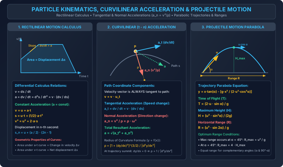
Diagram 2: D'Alembert's Principle, Work-Energy, Impulse & Rigid Body Rolling
6. Standard Practice Guidelines & Boundary Conditions
6.1 Codal Provisions & Dynamic Engineering Rules
- Pile Driving Dynamic Resistance (IS 2911 Part 1/Sec 1):
- In geotechnical engineering, the ultimate bearing capacity of a driven pile is estimated from the energy delivered by the falling hammer:
- Engineering News Record (ENR) Formula:
- Hiley Dynamic Formula (Work-Energy + Momentum): where is hammer weight, is pile weight, is plastic set per blow, is temporary elastic compression, and is restitution coefficient of the pile cushion cap.
- In geotechnical engineering, the ultimate bearing capacity of a driven pile is estimated from the energy delivered by the falling hammer:
- Horizontal Curve Superelevation & Side Friction (IRC:73):
- On highway curves, centrifugal acceleration is balanced by cross-slope superelevation and lateral tyre pavement friction :
- Under IRC standards, maximum superelevation is capped at (plain terrain) and design lateral friction is limited to .
- Bridge Dynamic Impact Allowance (IRC:6 / IRS Bridge Rules):
- High-speed vehicular and train live loads induce dynamic amplification over static axle loads.
- IRC:6 specifies an impact factor for reinforced concrete bridges, where is loaded span length.
7. Critical Failure Modes & Edge Cases
7.1 Neglecting Reversed Direction in D'Alembert Inertia Forces
- Fatal Error: Drawing the inertia force in the same direction as acceleration (), which doubles the effective dynamic force!
- Correct Formulation: D'Alembert's principle demands a reversed effective force: If an elevator accelerates upward (), the inertia force acts downward (), producing an apparent weight .
7.2 The Plastic Collision Energy Paradox
- When two bodies stick together after impact (), momentum is 100% conserved, but kinetic energy is NOT conserved.
- Many engineers incorrectly apply conservation of mechanical energy across the impact zone, overestimating the remaining kinetic energy and dramatically under-sizing structural shock absorbers.
7.3 Rolling vs Slipping Threshold on Steep Slopes
- If the inclination of an inclined plane exceeds the threshold , the required friction force exceeds the limiting static friction ().
- Pure rolling ceases, and the body undergoes combined sliding and spinning with kinetic friction . The kinematic equality no longer holds!
8. Worked Numerical Problems
Problem 1: Pile Driver Dynamics & Soil Dynamic Resistance Analysis
Statement: A diesel pile driver has a drop hammer of mass that falls freely under gravity from a height of () onto a precast concrete pile of mass standing vertically at ground level. The collision is completely plastic (), such that the hammer and pile move together immediately after impact. The combined system penetrates into the soil to a depth of . Calculate:
- The velocity of the hammer immediately prior to impact.
- The common velocity of the combined hammer-pile system immediately after impact.
- The kinetic energy lost during the impact collision, and the percentage of energy dissipated.
- The average dynamic soil resistance opposing penetration using the Work-Energy Theorem.
Solution & Calculations:
        HAMMER (M = 1000 kg)
        +---------+
        |         |  Falling freely from height h = 2.50 m
        +---------+
             |
             v v_0 = sqrt(2gh)
      ============== GROUND LEVEL
        +---------+
        | PILE    |  Stationary mass m = 400 kg
        |         |
        |         |  Penetration s = 0.050 m against soil resistance R_s
        +---------+
Step 1: Pre-Impact Velocity of Hammer ()
Applying the work-energy relation for free fall:
Kinetic energy of hammer just before impact:
Step 2: Post-Impact Velocity of Combined Hammer and Pile ()
Because external impulsive forces during the split-second impact are negligible compared to internal contact forces, linear momentum is conserved vertically downward:
Step 3: Energy Loss in Plastic Impact ()
Kinetic energy of the combined system immediately after impact:
Kinetic energy lost in plastic deformation, sound, and heat:
Step 4: Average Dynamic Soil Resistance ()
Apply the Work-Energy Theorem to the penetration phase from ground level to final rest at depth :
- Initial kinetic energy at start of penetration: .
- Final kinetic energy: .
- Work done by gravity (potential energy loss as mass descends through ):
- Work done by upward soil dynamic resistance:
Total Work-Energy Equation:
The ground mobilizes an average dynamic resistance of to arrest the pile.
Problem 2: Oblique Impact of Particles with Restitution
Statement: Two smooth spherical bodies and collide obliquely on a horizontal frictionless surface:
- Sphere : mass , initial speed directed at an angle to the common normal (line of impact).
- Sphere : mass , initial speed moving directly head-on along the common normal towards (). The coefficient of restitution between the spheres is . Determine:
- The post-impact velocity components and resultant speeds of both spheres.
- The deflection angles of both spheres after collision.
- The total kinetic energy lost during the oblique collision.
Solution & Calculations:
          Tangential Axis (t)
                  ^
                  |    Line of Impact (n)
      Sphere A    |    Sphere B
        (m1)      |      (m2)
     u1 \ 30°     |
         \        |       u2
          +-------+-------+ <-----------
                 (0,0)
Step 1: Resolve Initial Velocities into Normal () and Tangential () Components
Choose the -axis along the common normal (pointing from to ) and the -axis along the common tangent:
- For Sphere :
- For Sphere :
Step 2: Tangential Velocities Remain Unchanged
Because the contact surfaces are frictionless:
Step 3: Normal Velocities ()
- Conservation of Linear Momentum along the line of impact ():
- Newton's Law of Restitution along the line of impact:
- Substitute into the momentum equation:
Step 4: Resultant Post-Impact Speeds and Deflection Angles
- For Sphere :
- For Sphere :
Step 5: Kinetic Energy Lost in Collision
- Initial Kinetic Energy:
- Final Kinetic Energy:
- Energy Dissipated:
Problem 3: The Great Incline Race: Rolling of Rigid Bodies Without Slipping
Statement: Three homogeneous circular bodies of identical total mass and outer radius are released simultaneously from rest at the top of a rough inclined plane of angle and length ():
- Body 1: Solid Sphere ()
- Body 2: Solid Cylinder ()
- Body 3: Thin Cylindrical Hoop () Assuming all bodies roll down the plane without slipping:
- Calculate the linear acceleration of each body.
- Determine the linear velocity and elapsed time for each body to reach the base of the incline.
- Calculate the minimum coefficient of static friction required for each body to maintain pure rolling without slip.
Solution & Calculations:
Formula Framework:
From Section 3.5:
Here , .
1. Solid Sphere ():
- Acceleration:
- Final Velocity at Base ():
- Time to Base:
- Minimum Friction Coefficient:
2. Solid Cylinder ():
- Acceleration:
- Final Velocity at Base:
- Time to Base:
- Minimum Friction Coefficient:
3. Thin Cylindrical Hoop ():
- Acceleration:
- Final Velocity at Base:
- Time to Base:
- Minimum Friction Coefficient:
Incline Race Conclusion:
- The Solid Sphere arrives first because it has the smallest moment of inertia constant (), diverting the least potential energy into rotational kinetic energy.
- The Thin Hoop arrives last because all its mass is concentrated at radius , maximizing rotational inertia ().
9. Comparative Exam Analysis
| Parameter / Feature | GATE CE | UPSC ESE | SSC JE | RRB JE | State AE |
|---|---|---|---|---|---|
| Weightage | 2 - 4 Marks (NAT / MCQ) | 12 - 20 Marks (Obj + Conv) | 4 - 6 Marks (Direct CBT) | 3 - 5 Marks (Direct CBT) | 4 - 8 Marks (Obj + Conv) |
| Primary Question Type | Incline rolling acceleration order, Oblique impact vector restitution, Curvilinear | Full derivation of projectile parabolic equation, Pile driver work-energy, D'Alembert systems | Equations of motion (), Max range at | Projectile time of flight formula, Conservation of momentum | Elevator apparent weight (), Superelevation |
| Tricky Traps | Assuming affects tangential velocity; Forgetting mass inertia in pure rolling | Forgetting potential energy loss during pile penetration | Using vs in CBT calculation speed | Confusing acceleration with velocity at projectile summit (, ) | Forgetting that pure rolling acceleration is independent of mass and radius |
| Speed vs Depth | Analytical precision, exact multi-step equations | Comprehensive handwritten step-by-step calculus | Rapid 20-second formula recall | Direct 15-second identification | Standard textbook kinematics & dynamics problems |
10. Common Pitfalls & Traps
- Velocity vs Acceleration at Projectile Summit:
- At the highest point of a parabolic trajectory, vertical velocity is zero (), but acceleration is NOT zero (). The horizontal velocity remains constant ().
- Normal Acceleration Along a Straight Path:
- On a straight path, the radius of curvature is infinite (), so normal acceleration is identically zero (). Normal acceleration exists ONLY when the path curves.
- Restitution Coefficient in Oblique Collisions:
- Applying to the total resultant velocities instead of the normal velocity components along the line of impact. Tangential velocities are completely unaffected by !
- Conservation of Energy Across Inelastic Impacts:
- Applying when two bodies collide. Unless the impact is explicitly declared perfectly elastic (), kinetic energy is always lost ().
- Believing Rolling Acceleration Depends on Mass or Size:
- In pure rolling down an incline, . A tiny marble and a giant bowling ball have identical and will roll down the slope with identical acceleration and finish in a dead heat!
11. Real-World Civil & Structural Applications
- Geotechnical Driven Piles (IS 2911):
- High-energy hydraulic and diesel drop hammers drive heavy precast concrete piles into dense sands and load-bearing strata, applying the Work-Energy and Impulse-Momentum principles to determine allowable load capacity.
- Highway Curve Geometry & Superelevation (IRC:73):
- Curvilinear normal acceleration dictates horizontal curve radii, transition spirals, and superelevation banking to prevent high-speed vehicles from skidding or overturning.
- Bridge Pier Protection Against Ship Collision:
- Navigational bridge piers in major rivers and estuaries are equipped with sacrificial fender cells designed using impulse-momentum and energy dissipation principles to absorb vessel impact.
- Earthquake Base Isolators & Tuned Mass Dampers:
- High-rise towers (e.g., Taipei 101) install massive suspended pendulum spheres that swing counter to seismic ground motion, dissipating dynamic energy through inertial mass damping.
12. Comprehensive Summary & Quick Revision Guide
- Kinematics Equations: , , , .
- Path Coordinates: (speed change), (direction change), .
- Projectile Trajectory: ; ; ; . Max range at .
- D'Alembert's Principle: ; adds inertia force opposing acceleration.
- Work-Energy Theorem: ; Work of spring .
- Impulse-Momentum: .
- Impact Restitution: ; Tangential velocities unchanged ().
- Incline Rolling Acceleration: where .
- Solid Sphere: (Fastest).
- Solid Cylinder: .
- Thin Hoop: (Slowest).
13. Practice Problems for Self-Assessment
-
Problem 1 (Projectile Motion): A stone is projected from the top of a cliff high with an initial velocity of at an angle of above the horizontal (). Calculate the total time taken for the stone to hit the ground at the base of the cliff, and the horizontal distance traversed. (Answer: . Horizontal distance )
-
Problem 2 (Elevator D'Alembert Apparent Weight): A civil engineer weighing stands on a spring balance inside an elevator cabin. If the elevator accelerates downwards at , what is the reading shown on the balance? What would the reading be if the elevator cable snapped and it fell freely? (Answer: Downward acceleration gives apparent weight (or ). In free fall, (Weightlessness))
-
Problem 3 (Direct Elastic Collision): A railway wagon of mass moving at collides directly with a stationary wagon of mass . If the collision is perfectly elastic (), calculate the velocities of both wagons immediately after impact. (Answer: (rebounding backwards). (moving forward))
14. References & Standard Texts
- Beer, F. P., Johnston, E. R., Cornwell, P. J. — Vector Mechanics for Engineers: Dynamics, 12th Edition, McGraw-Hill.
- Hibbeler, R. C. — Engineering Mechanics: Dynamics, 14th Edition, Pearson Education.
- Meriam, J. L., Kraige, L. G., Bolton, J. N. — Engineering Mechanics: Dynamics, 9th Edition, John Wiley & Sons.
- Timoshenko, S. P., Young, D. H. — Engineering Mechanics, 5th Edition, McGraw-Hill.
- Bureau of Indian Standards & Indian Roads Congress:
- IS 2911 (Part 1/Sec 1):2010 — Design and Construction of Pile Foundations (Driven Piles).
- IRC:73-1980 — Geometric Design Standards for Rural Highways (Superelevation and Sight Distance).
- IRC:6-2017 — Standard Specifications and Code of Practice for Road Bridges (Section II: Loads & Dynamic Impact).