Friction & Engineering Applications (Coulomb Laws, Wedges, Ladders, Belt Friction & Screws)
In this chapter (1 topics)
On this page
- 1. Executive Summary & Core Definitions
- Core Definitions
- 2. Foundational Principles & Governing Laws
- 2.1 Coulomb's Laws of Dry Friction
- 2.2 Cone of Friction
- 3. Step-by-Step Analytical Derivations
- 3.1 Equivalence of Angle of Repose and Angle of Friction
- 3.2 Belt Friction & The Capstan Equation
- 3.3 Screw Jack Mechanics & Efficiency
- 3.4 Wedge Friction & Equilibrium
- 4. Key Formulas & Summary Tables
- Table 4.1: Master Friction Formulas
- Table 4.2: Typical Coefficients of Static Friction (μs) in Civil Engineering
- 5. Visual Architectural Diagrams
- Diagram 1: Coulomb Friction Laws, Angle of Friction & Angle of Repose
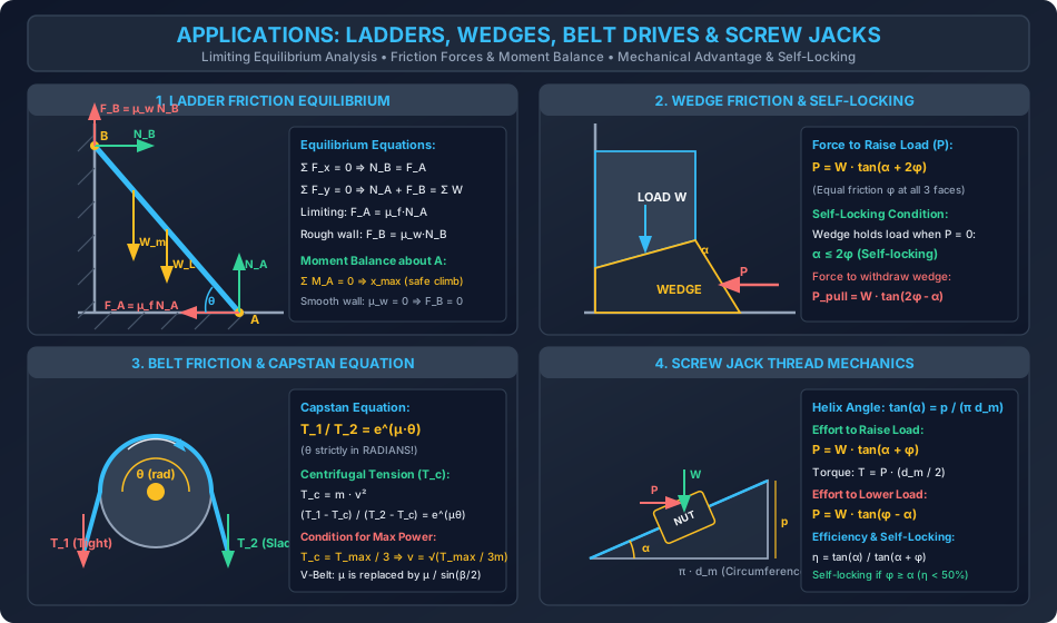
- Diagram 2: Applications: Ladders, Wedges, Belt Drives & Screw Jacks
- 6. Standard Practice Guidelines & Boundary Conditions
- 6.1 Civil Engineering Boundary Conditions & Codes
- 7. Critical Failure Modes & Edge Cases
- 7.1 Ladder Instability: Base Slip vs Top Wall Slip
- 7.2 Belt Creep vs Belt Slip
- 7.3 Overhauling vs Self-Locking in Lifting Jacks
- 8. Worked Numerical Problems
- Problem 1: Ladder Friction on Verge of Slipping (Smooth vs Rough Wall)
- Problem 2: Wedge Friction, Driving Force & Self-Locking Analysis
- Problem 3: Flat Belt Drive (Centrifugal Tension & Power) & Screw Jack Mechanics
- 9. Comparative Exam Analysis
- 10. Common Pitfalls & Traps
- 11. Real-World Civil & Structural Applications
- 12. Comprehensive Summary & Quick Revision Guide
- 13. Practice Problems for Self-Assessment
- 14. References & Standard Texts
1. Executive Summary & Core Definitions
Friction is the tangential contact resistance developed at the interface between two contacting bodies that opposes or tends to oppose impending or ongoing relative sliding motion. In civil and structural engineering, friction is fundamentally dual-natured: it provides essential stabilizing forces (such as sliding resistance beneath gravity retaining walls, bridge bearing restraint, sheet pile anchor grip, and tendon friction in post-tensioned prestressed concrete), while simultaneously presenting kinetic energy losses, wear, and mechanical resistance in construction machinery, cable haulage systems, and screw-operated lifting equipment.
       IMPENDEING RELATIVE MOTION --->
+-------------------------------------------------+
|                   SLIDING BODY                  |
+-------------------------------------------------+
       <--- TANGENTIAL FRICTION FORCE (F)
================ INTERFACE ========================
////////////////// SUPPORT ////////////////////////
Core Definitions
- Dry Friction (Coulomb Friction): Tangential resistance developed between unlubricated solid surfaces in contact under normal compression.
- Static Friction (): The self-adjusting tangential force that maintains relative rest between surfaces up to the onset of motion ().
- Limiting Friction ( or ): The maximum static friction force developed at the verge or instant of impending relative sliding:
- Kinetic (Dynamic) Friction (): The tangential resistance opposing relative motion once sliding has commenced. For almost all engineering materials, :
- Angle of Friction (): The angle between the resultant reaction force () and the normal reaction () when the body is in limiting equilibrium:
- Angle of Repose (): The maximum inclination of a rough plane with the horizontal at which a granular mass or loose block can rest without sliding down solely under its own weight:
- Cone of Friction: An inverted right-circular cone having its vertex at the point of contact, its axis along the normal reaction, and semi-vertex angle equal to . The resultant reaction vector must lie within or on this cone for static equilibrium to hold.
- Self-Locking: The mechanical condition where friction prevents reverse motion or loosening under external loads without the application of an external driving or release force (e.g., screw jacks with lead angle , wedges with taper angle ).
2. Foundational Principles & Governing Laws
2.1 Coulomb's Laws of Dry Friction
Dry friction phenomena are governed by classical experimental laws established by Guillaume Amontons (1699) and Charles-Augustin de Coulomb (1781):
- Law of Proportionality: The maximum limiting static friction force is directly proportional to the normal compressive force between the contacting bodies:
- Independence of Apparent Contact Area: To a high degree of engineering approximation, the limiting friction force is independent of the nominal or apparent macroscopic area of contact between solid bodies.
- Independence of Sliding Velocity (Kinetic Regime): Once sliding is initiated, kinetic friction is approximately independent of the sliding velocity over moderate speed ranges, though it drops slightly from the limiting static peak.
- Directionality: Friction force always acts tangentially along the contact plane and opposes the direction of relative impending or actual velocity.
Friction Force (F)
    ^
    |             Peak: F_max = μ_s · N (Limiting Friction)
    |                /\
    |               /  \_________ F_k = μ_k · N (Kinetic Friction)
    |              /
    |  Static     /      Dynamic / Kinetic
    |  F = P     /       Sliding Regime
    |           /
    +----------+------------------------------------> Applied Force (P)
              Impending
              Motion
2.2 Cone of Friction
When a force acts on a block resting on a horizontal plane:
- Normal reaction .
- Friction force .
- The total contact reaction is the vector sum .
- Magnitude: .
- When reaches its limiting value , the reaction vector tilts to its maximum angle relative to the normal.
- Because the applied horizontal force could act in any azimuthal direction in the plane, the locus of all possible limiting reaction vectors forms an inverted right-circular cone called the Cone of Friction with semi-vertex angle .
3. Step-by-Step Analytical Derivations
3.1 Equivalence of Angle of Repose and Angle of Friction
Consider a block of weight resting on an inclined plane whose angle of inclination with the horizontal is gradually increased to until the block is on the verge of sliding down the incline.
            ^ Normal N
            |     /
            |    / Friction F_lim (upwards)
            |   /
        +-------+
        | BLOCK |
        +-------+
       /        |
      /         | Weight W (vertically down)
     /          v
    / θ_r
---+------------------------
- Resolve forces along the inclined plane (parallel to plane):
- Resolve forces normal to the inclined plane (perpendicular to plane):
- Apply Coulomb's law of limiting friction:
- Substitute expressions from (1) and (2):
- From the definition of angle of friction :
3.2 Belt Friction & The Capstan Equation
Consider a flexible flat belt wrapped around a cylindrical pulley or capstan drum of radius over a contact angle (lap angle) radians. The belt is on the verge of slipping in the direction of ().
                dθ/2   dθ/2
                  \     /
                   \   /
                    \ /
          T+dT <----(ds)----< T
                     / \
                    /   \
                   / dN  \
                  v       v
                     μ·dN
Take an infinitesimal segment of the belt subtending an angle :
- Tensions at ends: and .
- Normal reaction on element: .
- Friction force opposing motion: .
- Centrifugal force acting radially outwards: , where is mass per unit length and is belt speed.
Equilibrium in the radial (normal) direction:
For small , , and neglecting second-order differentials ():
Let denote the centrifugal tension:
Equilibrium in the tangential direction:
Since :
Integrate from slack side (, angle ) to tight side (, angle ):
When belt velocity is negligible ():
Condition for Maximum Power Transmission:
Power transmitted is:
From the tension ratio . For maximum permissible tension :
Differentiate with respect to and equate to zero:
3.3 Screw Jack Mechanics & Efficiency
A square-threaded screw jack has mean diameter , pitch , and lead angle (helix angle) . Unwrapping one thread turn of the helix onto a flat development yields an inclined plane of base and height :
        /|
       / |
      /  | p (Pitch)
     /   |
    / α  |
   +-----+
    π·d_m (Circumference)
1. Effort Required to Raise Load :
The load moves up the incline against gravity and friction. The horizontal effort acts at mean radius :
Torque required to raise load:
2. Effort Required to Lower Load :
When lowering, the friction force reverses to oppose downward motion:
- If (Self-locking screw), an effort is required to force the load down:
- If (Overhauling screw), the load descends by itself, and a restraining effort is required to prevent it from spinning out of control.
3. Efficiency of Screw Jack ():
4. Self-Locking Condition:
For self-locking:
Substitute into efficiency:
3.4 Wedge Friction & Equilibrium
A wedge of taper angle is driven horizontally under a load block resting against a vertical wall. All contact faces have friction angle .
     VERTICAL WALL
          |   +-------+
          |   | BLOCK | (Weight W)
          |   +-------+
          |   /       |
          |  /  WEDGE | <---- P (Driving force)
          | /  angle α|
  ========+===========+=========== FLOOR
-
Free Body Diagram of Block:
- Normal and friction forces at the vertical wall combine to give resultant reaction , inclined at below the horizontal normal.
- At the inclined wedge-block interface, resultant reaction makes angle with the normal to the inclined plane (inclined at to the vertical).
- Horizontal equilibrium: .
- Vertical equilibrium: .
- Combining equations yields:
-
Free Body Diagram of Wedge:
- Acted upon by driving force , reaction from block, and floor reaction (inclined at to vertical normal).
- Horizontal equilibrium: .
- Vertical equilibrium: .
- Substituting and simplifying gives the exact closed-form relation:
-
Self-Locking of Wedge:
- When the driving force is removed, the wedge will remain in place without slipping back if:
- The force required to pull out / withdraw the wedge is:
4. Key Formulas & Summary Tables
Table 4.1: Master Friction Formulas
| Application | Governing Formula | Key Variables & Notes |
|---|---|---|
| Coulomb Static Limiting | Independent of macroscopic contact area | |
| Angle of Friction | Angle of resultant reaction to normal | |
| Angle of Repose | Maximum slope without self-sliding | |
| Flat Belt Drive | must be in radians | |
| Centrifugal Tension | in kg/m, in m/s | |
| Max Power Speed (Belt) | Occurs strictly at | |
| V-Belt / Rope Drive | (usually ) | |
| Ladder Friction | ; for rough wall | |
| Wedge Lifting Effort | Wedge taper , friction angle | |
| Wedge Withdrawal Force | Self-locking if | |
| Screw Jack Raising Effort | ; Torque | |
| Screw Jack Lowering Effort | Valid when (self-locking) | |
| Screw Jack Efficiency | for any self-locking screw |
Table 4.2: Typical Coefficients of Static Friction () in Civil Engineering
| Material Interface | State / Condition | Typical Range | Practical Design Value |
|---|---|---|---|
| Concrete on Hard Rock | Clean, sound surface | (Dam foundation) | |
| Concrete on Coarse Sand / Gravel | Dry or moist | (Retaining walls) | |
| Concrete on Silt / Clay | Consolidated / moist | ||
| Masonry on Masonry | Dry joint | ||
| Structural Steel on Structural Steel | Mill scale / clean dry | (Slip-critical bolts) | |
| Steel on Steel (Oiled/Greased) | Boundary lubrication | (Machinery) | |
| PTFE (Teflon) on Stainless Steel | Polished mirror finish | (Bridge bearings) | |
| Rubber on Dry Concrete | Pavement tyre contact | (Road stopping sight) | |
| Rubber on Wet Concrete | Water film / rain | (IRC:73 skid resistance) |
5. Visual Architectural Diagrams
Diagram 1: Coulomb Friction Laws, Angle of Friction & Angle of Repose
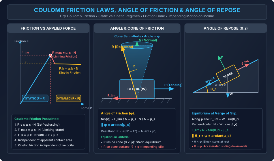
Diagram 2: Applications: Ladders, Wedges, Belt Drives & Screw Jacks
6. Standard Practice Guidelines & Boundary Conditions
6.1 Civil Engineering Boundary Conditions & Codes
- Sliding Stability of Retaining Walls & Dams (IS 1904, IS 456, IS 6512):
- The factor of safety against sliding is defined as:
- Where is total vertical gravity load, is active earth pressure thrust, and is passive resistance at the toe or shear key.
- High-Strength Friction Grip (HSFG) Bolts (IS 800:2007 Cl. 10.4):
- HSFG connections transfer shear strictly through frictional traction between clamped plates without bolt shank bearing.
- Slip resistance: where is slip factor ( for blast-cleaned with grit, for normal uncleaned mill scale).
- Prestress Losses Due to Friction in Post-Tensioned Ducts (IS 1343:2012 Cl. 19.5.2):
- Friction loss equation: where is curvature friction coefficient () and is wobble effect coefficient ().
7. Critical Failure Modes & Edge Cases
7.1 Ladder Instability: Base Slip vs Top Wall Slip
- Smooth Wall ():
- Horizontal equilibrium dictates .
- Because , the maximum wall reaction is strictly capped at .
- If a climber ascends beyond a critical distance , the moment about the base exceeds , causing catastrophic base slip outward.
- Rough Wall ():
- Friction along the wall points vertically upwards, reducing the required normal reaction at the floor:
- This increases the allowable climb height significantly.
7.2 Belt Creep vs Belt Slip
- Belt Creep: A minor, unavoidable localized elastic phenomenon caused by the stretching of the belt under high tension on the driving side and contraction under low tension on the driven side. Causes a tiny loss in speed ratio (), but does not violate static friction bounds.
- Belt Slip: A macro-scale failure mode where the required tension ratio exceeds . The belt slides as a rigid body over the pulley surface, leading to rapid friction heating, glazing, and loss of drive.
7.3 Overhauling vs Self-Locking in Lifting Jacks
- In screw jacks, if (efficiency ), the load will back-drive the screw when the operator lets go of the lever, posing severe safety hazards on construction sites.
- Self-locking requires , guaranteeing safety against uncontrolled descent at the cost of lower mechanical efficiency ().
8. Worked Numerical Problems
Problem 1: Ladder Friction on Verge of Slipping (Smooth vs Rough Wall)
Statement: A uniform ladder of length and weight rests against a vertical wall at and a horizontal floor at . The ladder is inclined at to the horizontal. The coefficient of static friction at the floor is . A person of weight climbs up the ladder from . Determine the maximum distance measured along the ladder that the person can climb without the ladder slipping, for:
- Case (a): The vertical wall is smooth ().
- Case (b): The vertical wall is rough with .
Solution & Calculations:
  B +
    | \
    |  \ Ladder length L = 6.0 m
    |   \
    |    \ (Person W_m at distance x from A)
    |     \
    |      \ (Ladder CG W_L at L/2 = 3.0 m)
    |       \
    |        \
    +---------+ A (Inclination θ = 60°)
Step 1: Case (a) - Smooth Wall ()
- Equilibrium Equations:
- Limiting Friction at Floor :
- Horizontal Equilibrium:
- Moment Equilibrium about Base (): Divide through by : Substitute known values (): The person can safely climb up the ladder ( of its length).
Step 2: Case (b) - Rough Wall ()
When slipping impends, point moves downwards, so friction force acts vertically upwards along the wall.
-
Limiting Friction at Wall:
-
Vertical Equilibrium:
-
Horizontal Equilibrium:
-
Moment Equilibrium about Base ():
Divide through by :
Wall friction increases the safe climb distance by to ( of length).
Problem 2: Wedge Friction, Driving Force & Self-Locking Analysis
Statement: A heavy equipment foundation block weighing is to be raised slightly using a wedge with taper angle . The block is guided by a smooth vertical wall on one side. The coefficient of static friction is at all contact surfaces (block-wall, block-wedge, and wedge-floor). Neglect the self-weight of the wedge. Calculate:
- The angle of friction .
- The minimum horizontal driving force required to drive the wedge and raise the block.
- Check whether the wedge is self-locking upon removal of force .
- The horizontal force required to withdraw the wedge.
Solution & Calculations:
Step 1: Angle of Friction ()
Step 2: Driving Force to Raise Load
Using the closed-form analytical equilibrium relation derived in Section 3.4:
Let us verify via individual component reactions:
- Reaction at block-wedge interface ():
- Reaction at vertical wall ():
- Reaction at floor ():
- Total horizontal force on wedge:
Step 3: Self-Locking Verification
The self-locking condition for a wedge driven between a block and a horizontal floor is:
Here:
Since , the condition is SATISFIED. The wedge is self-locking; it will not slip back under the 20 kN load when is removed.
Step 4: Force to Withdraw Wedge ()
To pull out the wedge, the driving force must overcome the reversed friction resistance:
A pulling force of is required to release the wedge.
Problem 3: Flat Belt Drive (Centrifugal Tension & Power) & Screw Jack Mechanics
Statement:
- Belt Drive: A flat belt connects a motor to a conveyor drive pulley. The pulley diameter is and the angle of wrap is . The coefficient of static friction is . The belt has mass and maximum permissible working tension .
- Find the optimal belt speed and the maximum power that can be transmitted.
- Calculate the power transmitted if the belt runs at .
- Screw Jack: A square-threaded screw jack has a pitch of and mean diameter . The coefficient of friction is . A load of is to be raised.
- Determine the effort required at the mean radius, the torque , the mechanical efficiency , and verify self-locking.
Solution & Calculations:
Part A: Belt Drive Analysis
-
Convert Lap Angle to Radians:
-
Limiting Tension Ratio:
-
Optimal Speed for Maximum Power:
-
Effective Tensions at :
-
Maximum Transmitted Power:
-
Power at :
Part B: Screw Jack Analysis
- Helix (Lead) Angle :
- Friction Angle :
- Effort at Mean Radius to Raise :
- Torque Required:
- Efficiency ():
- Self-Locking Verification: Since (and ), the jack is unconditionally self-locking.
9. Comparative Exam Analysis
| Parameter / Feature | GATE CE | UPSC ESE | SSC JE | RRB JE | State AE |
|---|---|---|---|---|---|
| Weightage | 1 - 2 Marks (NAT / MCQ) | 6 - 12 Marks (Obj + Conv) | 2 - 4 Marks (Direct CBT) | 2 - 3 Marks (Direct CBT) | 3 - 6 Marks (Obj + Short) |
| Primary Question Type | Ladder friction limit, Wedge equilibrium, Belt max power | Screw jack derivations, Multi-surface wedges, Self-locking proofs | Definition of , , Repose angle | Belt tension ratio formula, Direction of friction force | Cone of friction angle, Ladder slip equations |
| Tricky Traps | Forgetting centrifugal tension ; Using degrees in | Sign convention on rough walls ( upwards on ladder) | Confusing and | Confusing kinetic friction independence of area | Overestimating self-locking efficiency () |
| Speed vs Depth | High analytical depth, exact numbers | Mixed: rapid memory + full analytical steps | Pure speed: 20-30 seconds per question | Direct formula recall: 15-20 seconds | Standard textbook derivations & formulas |
10. Common Pitfalls & Traps
- Using Degrees instead of Radians in the Belt Friction Equation:
- Incorrect Centrifugal Tension Formulation:
- Centrifugal tension does NOT depend on belt tension; it is solely .
- It acts equally on both tight and slack sides, reducing the net normal force against the pulley. Hence it must be subtracted from both:
- Misidentifying Friction Direction at Ladder Wall:
- When a ladder slips, its top end moves downward against the vertical wall.
- Therefore, wall friction points UPWARD, assisting the floor normal reaction ().
- Asserting Self-Locking Machines Have :
- Any mechanism that is self-locking () mathematically possesses efficiency . An efficiency implies that the machine will overhaul (reverse spin) under load.
- Assuming Friction Depends on Contact Surface Area:
- By Coulomb's law, friction force is independent of apparent contact area. A brick resting on its broad side or narrow face develops identical limiting friction under the same normal load.
11. Real-World Civil & Structural Applications
- Gravity Retaining Wall Base Sliding Stability:
- The primary resisting force preventing lateral sliding of a mass concrete or cantilever retaining wall under active backfill pressure is the interface base friction , where is the soil-concrete interface friction angle (typically to ).
- Elastomeric and Pot Bearings for Bridges:
- Bridge expansion bearings utilize polished stainless steel sliding over virgin PTFE (Teflon) pads with mirror finishes, achieving static friction coefficients as low as to accommodate thermal expansion and shrinkage without inducing heavy lateral bending moments in bridge piers.
- Post-Tensioned Tendon Friction Losses (IS 1343):
- High-strength prestressing steel strands pulled through curved metal ducts in long-span bridge girders suffer significant tension losses due to duct curvature friction () and unintentional wobbling ().
- Friction Piles in Geotechnical Foundations:
- Skin friction ( or ) carries the entirety or majority of building loads in deep soft clay or loose sand strata where end-bearing rock is unavailable.
12. Comprehensive Summary & Quick Revision Guide
- Coulomb Friction Equation: ; at impending slip ; during sliding ().
- Friction Angle & Repose Angle: ; .
- Cone of Friction: Semi-vertical apex angle . If resultant reaction falls inside cone, body is stable; if on boundary, slip impends.
- Ladder Equilibrium: Set up , , and take moments about the base . With rough wall: , .
- Wedge Equations:
- Raising load: .
- Self-locking condition: .
- Releasing / withdrawal force: .
- Belt Drive Principles:
- Ratio of effective tensions: .
- Centrifugal tension: .
- Maximum power condition: .
- V-belt modification: Replace with .
- Screw Jack Equations:
- Pitch angle: .
- Raising effort: .
- Lowering effort: (when ).
- Efficiency: (for self-locking).
13. Practice Problems for Self-Assessment
-
Problem 1 (Ladder Equilibrium): A uniform ladder long weighs and leans against a smooth vertical wall at an inclination of to the horizontal (). If the coefficient of friction between ladder and floor is , calculate the maximum weight of an electrician that can stand on the very top rung of the ladder without initiating base slip. (Answer: )
-
Problem 2 (Belt Drive Transmission): A flat belt of density , width , and thickness wraps over an angle of on a driving pulley. If and the allowable belt stress is , calculate: (a) The centrifugal tension for maximum power transmission. (b) The maximum power transmissible by the belt drive. (Answer: (a) , (b) at )
-
Problem 3 (Screw Jack Mechanics): A screw jack with double square threads has pitch and mean diameter . If : (a) Determine whether the jack is self-locking or overhauling. (b) Compute the mechanical efficiency . (Answer: Double start implies lead . Since , the jack is Self-Locking. Efficiency )
14. References & Standard Texts
- Beer, F. P., Johnston, E. R., Mazurek, D. F. — Vector Mechanics for Engineers: Statics, 12th Edition, McGraw-Hill.
- Hibbeler, R. C. — Engineering Mechanics: Statics, 14th Edition, Pearson Education.
- Meriam, J. L., Kraige, L. G. — Engineering Mechanics: Statics, 8th Edition, John Wiley & Sons.
- Bhavikatti, S. S. — Engineering Mechanics, 6th Edition, New Age International Publishers.
- Bureau of Indian Standards (BIS):
- IS 456:2000 — Plain and Reinforced Concrete - Code of Practice (Sliding Stability).
- IS 800:2007 — General Construction in Steel - Code of Practice (HSFG Friction Grip Bolted Joints).
- IS 1343:2012 — Code of Practice for Prestressed Concrete (Friction and Wobble Losses).
- IS 1904:1986 — Code of Practice for Design and Construction of Foundations in Soils (Safety against Sliding).