EM-04 Chapter 04 · Centroids and Moments of Inertia

Centroids, Center of Gravity & Moments of Inertia (Parallel Axis, Product of Inertia, Gyration, Mohr's Circle)

In this chapter (1 topics)
On this page
  1. 1. Executive Summary & Core Definitions
  2. Core Definitions
  3. 2. Foundational Principles & Governing Axioms
  4. 2.1 The Two Fundamental Theorems of Area Inertia
  5. 2.2 Product of Inertia Axioms & Symmetry
  6. 3. Step-by-Step Analytical Derivations
  7. 3.1 Derivation of the Parallel Axis Theorem
  8. 3.2 The Pappus-Guldinus Theorems
  9. 3.3 Principal Axes & Mohr's Circle Transformation Equations
  10. 3.4 Mass Moment of Inertia of Elementary Bodies
  11. 4. Key Formulas & Summary Tables
  12. Table 4.1: Geometric Properties of Standard Plane Shapes
  13. Table 4.2: Mass Moments of Inertia of Standard Rigid Bodies (I = ∫ r2 dm)
  14. 5. Visual Architectural Diagrams
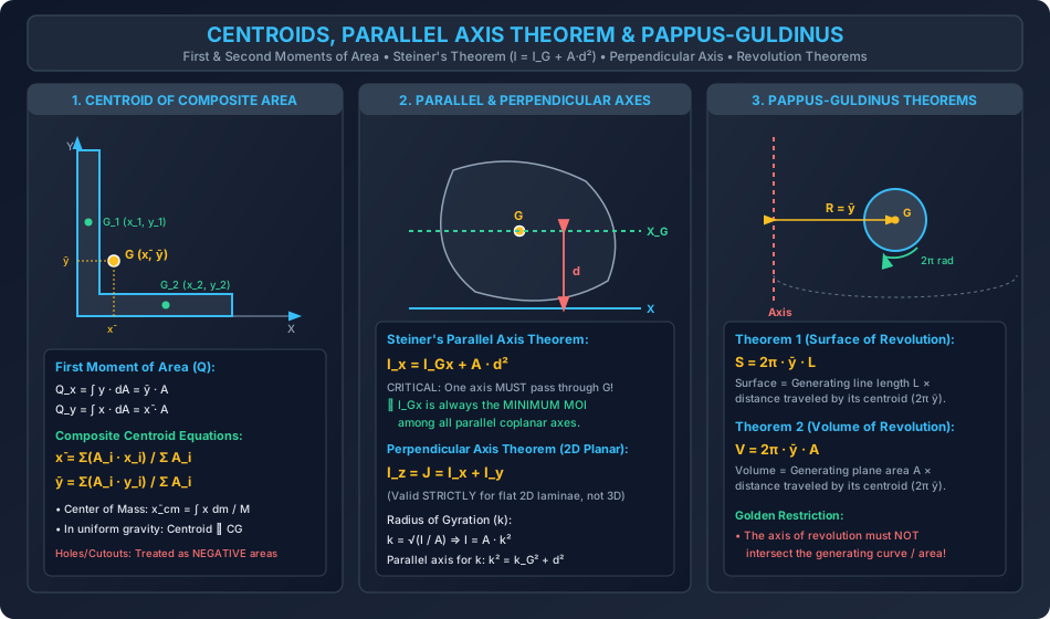
  15. Diagram 1: Centroids, Parallel Axis Theorem & Pappus-Guldinus
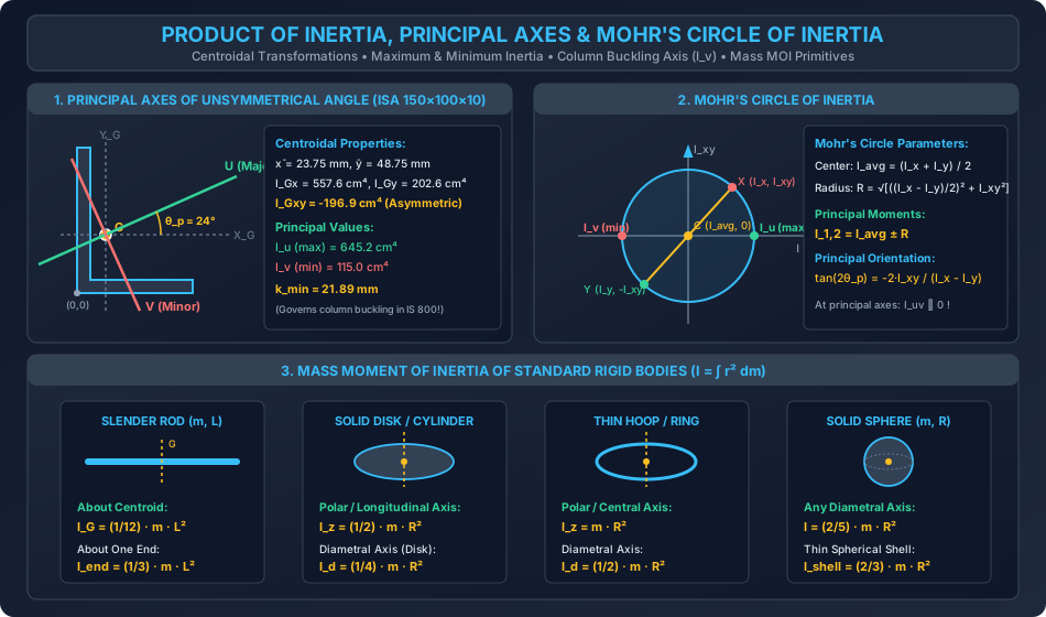
  16. Diagram 2: Product of Inertia, Principal Axes & Mohr's Circle of Inertia
  17. 6. Standard Practice Guidelines & Boundary Conditions
  18. 6.1 Codal Provisions for Structural Steel Sections (IS 800:2007)
  19. 7. Critical Failure Modes & Edge Cases
  20. 7.1 Applying Parallel Axis Theorem Between Two Non-Centroidal Axes
  21. 7.2 Cutouts and Negative Area Rules
  22. 7.3 Applying Perpendicular Axis Theorem to 3D Solids
  23. 8. Worked Numerical Problems
  24. Problem 1: Centroid & Moment of Inertia of an Unsymmetrical Angle Section (ISA 150×100×10 mm)
  25. Problem 2: Principal Moments of Inertia, Orientation & Mohr's Circle for ISA 150×100×10
  26. Problem 3: Pappus-Guldinus Theorems & Rigid Body Mass Moment of Inertia
  27. 9. Comparative Exam Analysis
  28. 10. Common Pitfalls & Traps
  29. 11. Real-World Civil & Structural Applications
  30. 12. Comprehensive Summary & Quick Revision Guide
  31. 13. Practice Problems for Self-Assessment
  32. 14. References & Standard Texts

1. Executive Summary & Core Definitions

The geometrical and inertial properties of plane areas and three-dimensional rigid bodies represent fundamental pillars of structural mechanics, fluid statics, and structural dynamics. The first moment of area determines the centroid (xˉ,yˉ\bar{x}, \bar{y}) and governs shear stress distributions (τ=VQIb\tau = \frac{V Q}{I b}), while the second moment of area (moment of inertia, II) measures the resistance of a cross-section to flexural bending (σ=MyI\sigma = \frac{M y}{I}) and compressive column buckling (Pcr=π2EI(KL)2P_{cr} = \frac{\pi^2 E I}{(KL)^2}). In unsymmetrical civil engineering sections—such as cold-formed roof purlins, girt angles, and crane runway channels—the product of inertia (IxyI_{xy}) produces biaxial coupling, requiring principal axis transformation (u−vu - v) and Mohr's Circle analysis to identify the critical minimum radius of gyration (kmin⁡k_{\min}).

GEOMETRIC AXES vs PRINCIPAL AXES (ISA 150x100x10):
        Y
        ^           V (Minor Principal Axis: k_min = 21.89 mm)
        |          /
    +---+         /
    |   |        /
    |   |       /   U (Major Principal Axis: I_u = 645.2 cm^4)
    |   |      /   /
    |   |     /   /
    |   |    /   /   θ_p = 23.98°
    |   +---+---/---------> X
    |       G  /
    +---------+

Core Definitions

  • Centroid (GG): The geometric center of a plane area, curve, or volume; mathematically, the unique point at which the first moment of area or volume about any passing axis is identically zero.
  • Center of Mass / Center of Gravity (CG): The point at which the entire mass or weight of a body may be considered concentrated. In a uniform gravitational field, the Center of Gravity coincides identically with the Center of Mass and Centroid.
  • First Moment of Area (QQ): The integral of area elements multiplied by their distance from a reference axis: Qx=∫y dA=yˉA,Qy=∫x dA=xˉAQ_x = \int y \, dA = \bar{y} A, \quad Q_y = \int x \, dA = \bar{x} A
  • Second Moment of Area (Moment of Inertia, II): The integral of area elements multiplied by the square of their distance from a reference axis: Ix=∫y2 dA,Iy=∫x2 dAI_x = \int y^2 \, dA, \quad I_y = \int x^2 \, dA
  • Polar Moment of Inertia (JJ or IpI_p): The moment of inertia of a plane area about an axis perpendicular to its plane: J=∫r2 dA=∫(x2+y2) dA=Ix+IyJ = \int r^2 \, dA = \int (x^2 + y^2) \, dA = I_x + I_y
  • Radius of Gyration (kk): The fictitious distance from the reference axis at which the entire area could be concentrated into a thin strip without altering its moment of inertia: k=IA  ⟺  I=Ak2k = \sqrt{\frac{I}{A}} \iff I = A k^2
  • Product of Inertia (IxyI_{xy}): The integral of area elements multiplied by both their xx and yy coordinate distances: Ixy=∫xy dAI_{xy} = \int x y \, dA
  • Principal Axes (u−vu - v): A pair of mutually orthogonal axes passing through the centroid about which the product of inertia is identically zero (Iuv=0I_{uv} = 0). One principal axis corresponds to the absolute maximum moment of inertia (IuI_u), and the other corresponds to the absolute minimum moment of inertia (IvI_v).
  • Mohr's Circle of Inertia: A graphical construct in the (I,Ixy)(I, I_{xy}) coordinate plane that visually represents the transformation of moments and products of inertia under arbitrary coordinate rotation.
  • Mass Moment of Inertia (ImI_m): A measure of the rotational inertia of a rigid body about a specified axis: Im=∫r2 dmI_m = \int r^2 \, dm

2. Foundational Principles & Governing Axioms

2.1 The Two Fundamental Theorems of Area Inertia

  1. Parallel Axis Theorem (Steiner's Theorem): The moment of inertia of an area about any arbitrary axis is equal to the moment of inertia about a parallel centroidal axis plus the product of the total area and the square of the perpendicular distance separating the two axes:

    Ix=IGx+Ady2,Iy=IGy+Adx2I_x = I_{Gx} + A d_y^2, \quad I_y = I_{Gy} + A d_x^2
    • Crucial Governing Axiom: One of the two parallel axes MUST pass through the centroid GG. The parallel axis theorem cannot be applied directly between two non-centroidal axes without first transforming through GG.
    • Corollary: Because Ad2≥0A d^2 \ge 0, the moment of inertia about a centroidal axis is the absolute minimum among all parallel axes in the plane.
  2. Perpendicular Axis Theorem: For any plane lamina lying in the x−yx-y plane, the polar moment of inertia about the perpendicular zz-axis passing through the origin is equal to the sum of the moments of inertia about the coplanar xx and yy axes:

    Iz=J=Ix+IyI_z = J = I_x + I_y
    • Crucial Governing Axiom: Valid STRICTLY for two-dimensional planar flat laminae. It cannot be applied to three-dimensional solid bodies.

2.2 Product of Inertia Axioms & Symmetry

  1. Sign of Product of Inertia: Unlike moments of inertia (Ix,Iy>0I_x, I_y > 0), the product of inertia IxyI_{xy} can be positive, negative, or zero depending on the distribution of area in the four Cartesian quadrants.
  2. Symmetry Theorem: If a plane area possesses at least one axis of geometric symmetry, the product of inertia with respect to that axis and any perpendicular axis is identically zero: Symmetry about X or Y  ⟹  Ixy=0\text{Symmetry about } X \text{ or } Y \implies \mathbf{I_{xy} = 0} Consequently, for symmetric sections (I-beams, T-sections, rectangular channels, circular pipes), the geometric centroidal axes are already the principal axes!
  3. Parallel Axis Theorem for Product of Inertia: Ixy=IGxy+AxˉyˉI_{xy} = I_{Gxy} + A \bar{x} \bar{y}

3. Step-by-Step Analytical Derivations

3.1 Derivation of the Parallel Axis Theorem

Consider a plane area AA in the x−yx-y plane. Let G(xˉ,yˉ)G(\bar{x}, \bar{y}) be the centroid. Define centroidal coordinates x′,y′x', y' such that:

x=xˉ+x′,y=yˉ+y′x = \bar{x} + x', \quad y = \bar{y} + y'

By definition of centroid:

∫x′ dA=0,∫y′ dA=0\int x' \, dA = 0, \quad \int y' \, dA = 0
Reference Y
    ^       Centroidal Y'
    |          ^
    |          |
    |          +--- Area dA (x', y')
    |          |
    |     d_x  |
    +--------->G (Centroid)
    |          |
    +------------------------> Reference X
              d_y

Now evaluate the moment of inertia about the reference xx-axis:

Ix=∫y2 dA=∫(yˉ+y′)2 dA=∫(yˉ2+2yˉy′+(y′)2)dAI_x = \int y^2 \, dA = \int (\bar{y} + y')^2 \, dA = \int \left(\bar{y}^2 + 2\bar{y}y' + (y')^2\right) dA Ix=yˉ2∫dA+2yˉ∫y′ dA+∫(y′)2 dAI_x = \bar{y}^2 \int dA + 2\bar{y} \int y' \, dA + \int (y')^2 \, dA

Since ∫dA=A\int dA = A, ∫y′ dA=0\int y' \, dA = 0, and ∫(y′)2 dA=IGx\int (y')^2 \, dA = I_{Gx}:

Ix=Ayˉ2+0+IGx  ⟹  Ix=IGx+Ady2I_x = A \bar{y}^2 + 0 + I_{Gx} \implies \mathbf{I_x = I_{Gx} + A d_y^2}

Similarly, for the product of inertia:

Ixy=∫xy dA=∫(xˉ+x′)(yˉ+y′) dAI_{xy} = \int x y \, dA = \int (\bar{x} + x')(\bar{y} + y') \, dA Ixy=xˉyˉ∫dA+xˉ∫y′ dA+yˉ∫x′ dA+∫x′y′ dAI_{xy} = \bar{x}\bar{y} \int dA + \bar{x} \int y' \, dA + \bar{y} \int x' \, dA + \int x' y' \, dA Ixy=IGxy+Axˉyˉ\mathbf{I_{xy} = I_{Gxy} + A \bar{x} \bar{y}}

3.2 The Pappus-Guldinus Theorems

Theorem 1 (Surface Area of Revolution):

Let a plane curve of length LL lying in a plane be rotated by an angle θ\theta (or a full 2π2\pi radians) about an axis in its plane that does not intersect the curve. Consider an infinitesimal arc length dLdL located at perpendicular distance yy from the axis. Upon rotation through 2π2\pi radians, dLdL sweeps out a ring surface area:

dAs=2πy dLdA_s = 2\pi y \, dL

Integrating over the entire length LL:

As=∫2πy dL=2π∫y dLA_s = \int 2\pi y \, dL = 2\pi \int y \, dL

By definition of the centroid of a line, ∫y dL=yˉL\int y \, dL = \bar{y} L. Therefore:

As=2πyˉL\mathbf{A_s = 2\pi \bar{y} L}

The surface area generated equals the length of the generating curve multiplied by the distance traveled by its centroid.

Theorem 2 (Volume of Revolution):

Let a plane area AA be rotated by 2π2\pi radians about a non-intersecting coplanar axis. An area element dAdA located at distance yy sweeps out a circular ring of volume:

dV=2πy dAdV = 2\pi y \, dA

Integrating over the entire area AA:

V=∫2πy dA=2π∫y dA=2π(yˉA)V = \int 2\pi y \, dA = 2\pi \int y \, dA = 2\pi (\bar{y} A) V=2πyˉA\mathbf{V = 2\pi \bar{y} A}

The volume generated equals the generating plane area multiplied by the distance traveled by its centroid.


3.3 Principal Axes & Mohr's Circle Transformation Equations

Let centroidal coordinates (x,y)(x, y) be rotated counter-clockwise through an angle θ\theta to new axes (x1,y1)(x_1, y_1):

x1=xcos⁡θ+ysin⁡θx_1 = x \cos\theta + y \sin\theta y1=−xsin⁡θ+ycos⁡θy_1 = -x \sin\theta + y \cos\theta
           Y          Y_1
           ^         ^
           |        /
           |       /
           |      / θ
           |     +---------> X_1
           |    /
           |   / θ
           +--+-------------> X

Substitute into Ix1=∫y12 dAI_{x1} = \int y_1^2 \, dA:

Ix1=∫(−xsin⁡θ+ycos⁡θ)2 dA=sin⁡2θ∫x2dA−2sin⁡θcos⁡θ∫xydA+cos⁡2θ∫y2dAI_{x1} = \int (-x \sin\theta + y \cos\theta)^2 \, dA = \sin^2\theta \int x^2 dA - 2\sin\theta\cos\theta \int xy dA + \cos^2\theta \int y^2 dA Ix1=Iysin⁡2θ−2Ixysin⁡θcos⁡θ+Ixcos⁡2θI_{x1} = I_y \sin^2\theta - 2 I_{xy} \sin\theta\cos\theta + I_x \cos^2\theta

Using trigonometric double-angle identities (cos⁡2θ=1+cos⁡2θ2\cos^2\theta = \frac{1 + \cos 2\theta}{2}, sin⁡2θ=1−cos⁡2θ2\sin^2\theta = \frac{1 - \cos 2\theta}{2}, 2sin⁡θcos⁡θ=sin⁡2θ2\sin\theta\cos\theta = \sin 2\theta):

Ix1=Ix+Iy2+(Ix−Iy2)cos⁡2θ−Ixysin⁡2θ\mathbf{I_{x1} = \frac{I_x + I_y}{2} + \left(\frac{I_x - I_y}{2}\right)\cos 2\theta - I_{xy}\sin 2\theta} Iy1=Ix+Iy2−(Ix−Iy2)cos⁡2θ+Ixysin⁡2θ\mathbf{I_{y1} = \frac{I_x + I_y}{2} - \left(\frac{I_x - I_y}{2}\right)\cos 2\theta + I_{xy}\sin 2\theta} Ix1y1=(Ix−Iy2)sin⁡2θ+Ixycos⁡2θ\mathbf{I_{x1y1} = \left(\frac{I_x - I_y}{2}\right)\sin 2\theta + I_{xy}\cos 2\theta}

Principal Orientation (θp\theta_p):

Principal axes occur when Ix1y1≡0I_{x1y1} \equiv 0:

(Ix−Iy2)sin⁡2θp+Ixycos⁡2θp=0  ⟹  tan⁡2θp=−2IxyIx−Iy\left(\frac{I_x - I_y}{2}\right)\sin 2\theta_p + I_{xy}\cos 2\theta_p = 0 \implies \mathbf{\tan 2\theta_p = -\frac{2 I_{xy}}{I_x - I_y}}

Principal Moments of Inertia (Iu,IvI_u, I_v):

Substituting θp\theta_p yields the maximum and minimum invariants:

Iu,v=Ix+Iy2±(Ix−Iy2)2+Ixy2\mathbf{I_{u, v} = \frac{I_x + I_y}{2} \pm \sqrt{\left(\frac{I_x - I_y}{2}\right)^2 + I_{xy}^2}}

Mohr's Circle Equation:

Eliminating θ\theta from the transformation equations:

(Ix1−Ix+Iy2)2+Ix1y12=(Ix−Iy2)2+Ixy2=R2\left(I_{x1} - \frac{I_x + I_y}{2}\right)^2 + I_{x1y1}^2 = \left(\frac{I_x - I_y}{2}\right)^2 + I_{xy}^2 = R^2

This is the equation of a circle in the (I,Ixy)(I, I_{xy}) plane with:

Center: C=(Ix+Iy2,0),Radius: R=(Ix−Iy2)2+Ixy2\text{Center: } \mathbf{C = \left(\frac{I_x + I_y}{2}, 0\right)}, \quad \text{Radius: } \mathbf{R = \sqrt{\left(\frac{I_x - I_y}{2}\right)^2 + I_{xy}^2}}

3.4 Mass Moment of Inertia of Elementary Bodies

1. Slender Rod of Mass mm and Length LL about Centroidal Transverse Axis:

Let linear mass density λ=m/L\lambda = m / L. Mass of element: dm=λ dx=mLdxdm = \lambda \, dx = \frac{m}{L} dx.

IG=∫−L/2L/2x2 dm=mL∫−L/2L/2x2 dx=mL[x33]−L/2L/2=m3L(L38−(−L38))=112mL2I_G = \int_{-L/2}^{L/2} x^2 \, dm = \frac{m}{L} \int_{-L/2}^{L/2} x^2 \, dx = \frac{m}{L} \left[\frac{x^3}{3}\right]_{-L/2}^{L/2} = \frac{m}{3L} \left(\frac{L^3}{8} - \left(-\frac{L^3}{8}\right)\right) = \mathbf{\frac{1}{12} m L^2}

About an axis passing through one end (by Parallel Axis Theorem with d=L/2d = L/2):

Iend=IG+m(L2)2=112mL2+14mL2=13mL2I_{\text{end}} = I_G + m \left(\frac{L}{2}\right)^2 = \frac{1}{12} m L^2 + \frac{1}{4} m L^2 = \mathbf{\frac{1}{3} m L^2}

2. Solid Circular Cylinder / Disk of Mass mm and Radius RR about Longitudinal Axis:

Let areal density σ=mπR2\sigma = \frac{m}{\pi R^2}. Take a thin circular ring element of radius rr and thickness drdr:

dm=σ(2πr dr)=2mR2r drdm = \sigma (2\pi r \, dr) = \frac{2m}{R^2} r \, dr Iz=∫0Rr2 dm=2mR2∫0Rr3 dr=2mR2[R44]=12mR2I_z = \int_0^R r^2 \, dm = \frac{2m}{R^2} \int_0^R r^3 \, dr = \frac{2m}{R^2} \left[\frac{R^4}{4}\right] = \mathbf{\frac{1}{2} m R^2}

4. Key Formulas & Summary Tables

Table 4.1: Geometric Properties of Standard Plane Shapes

Shape Area (AA) Centroid (yˉ\bar{y}) from Base Moment of Inertia (IGI_G) MOI about Base (IbaseI_{\text{base}})
Rectangle (b×hb \times h) bhb h h/2h / 2 IGx=bh312I_{Gx} = \frac{b h^3}{12} bh33\frac{b h^3}{3}
Triangle (b×hb \times h) 12bh\frac{1}{2} b h h/3h / 3 IGx=bh336I_{Gx} = \frac{b h^3}{36} bh312\frac{b h^3}{12}
Circle (Radius RR) πR2\pi R^2 RR IGx=IGy=πR44=πD464I_{Gx} = I_{Gy} = \frac{\pi R^4}{4} = \frac{\pi D^4}{64} -
Semicircle (Radius RR) πR22\frac{\pi R^2}{2} 4R3π≈0.4244R\frac{4R}{3\pi} \approx 0.4244 R IGx=0.1098R4≈(π8−89π)R4I_{Gx} = 0.1098 R^4 \approx \left(\frac{\pi}{8} - \frac{8}{9\pi}\right)R^4 πR48\frac{\pi R^4}{8} (Diameter)
Quarter Circle (RR) πR24\frac{\pi R^2}{4} 4R3π≈0.4244R\frac{4R}{3\pi} \approx 0.4244 R IGx=0.0549R4I_{Gx} = 0.0549 R^4 πR416\frac{\pi R^4}{16}
Ellipse (Semi-axes a,ba, b) πab\pi a b bb (from center) IGx=πab34,IGy=πa3b4I_{Gx} = \frac{\pi a b^3}{4}, I_{Gy} = \frac{\pi a^3 b}{4} -

Table 4.2: Mass Moments of Inertia of Standard Rigid Bodies (I=∫r2dmI = \int r^2 dm)

Body & Geometry Specified Axis Mass MOI (ImI_m) Radius of Gyration (kk)
Slender Rod (LL) Perpendicular through Center 112mL2\frac{1}{12} m L^2 L23≈0.2887L\frac{L}{2\sqrt{3}} \approx 0.2887 L
Slender Rod (LL) Perpendicular through End 13mL2\frac{1}{3} m L^2 L3≈0.5774L\frac{L}{\sqrt{3}} \approx 0.5774 L
Solid Cylinder / Disk (RR) Longitudinal Central Axis 12mR2\frac{1}{2} m R^2 R2≈0.7071R\frac{R}{\sqrt{2}} \approx 0.7071 R
Solid Cylinder / Disk (R,LR, L) Central Diametral Axis 14mR2+112mL2\frac{1}{4} m R^2 + \frac{1}{12} m L^2 R24+L212\sqrt{\frac{R^2}{4} + \frac{L^2}{12}}
Thin Cylindrical Shell / Hoop Longitudinal Central Axis mR2m R^2 RR
Solid Sphere (RR) Any Central Diameter 25mR2\frac{2}{5} m R^2 25R≈0.6325R\sqrt{\frac{2}{5}} R \approx 0.6325 R
Thin Spherical Shell (RR) Any Central Diameter 23mR2\frac{2}{3} m R^2 23R≈0.8165R\sqrt{\frac{2}{3}} R \approx 0.8165 R
Rectangular Plate (a×ba \times b) Perpendicular to Plate at GG 112m(a2+b2)\frac{1}{12} m (a^2 + b^2) a2+b212\sqrt{\frac{a^2 + b^2}{12}}

5. Visual Architectural Diagrams

Diagram 1: Centroids, Parallel Axis Theorem & Pappus-Guldinus

Centroid Theorems Parallel Axis and Pappus Guldinus

Diagram 2: Product of Inertia, Principal Axes & Mohr's Circle of Inertia

Product of Inertia Principal Axes and Mohrs Circle

6. Standard Practice Guidelines & Boundary Conditions

6.1 Codal Provisions for Structural Steel Sections (IS 800:2007)

  1. Compressive Buckling Governed by kmin⁡k_{\min} (Cl. 7.1.2):
    • In structural steel design, compressive strength (fcdf_{cd}) depends on the maximum slenderness ratio λ=KLr\lambda = \frac{KL}{r}.
    • For single-angle struts (e.g., roof truss web members, transmission tower diagonals), buckling always occurs about the minor principal axis v−vv - v, where the radius of gyration is minimum (rmin⁡=rvr_{\min} = r_v): λmax⁡=Lrv\lambda_{\max} = \frac{L}{r_v}
    • Attempting to design the strut using rxr_x or ryr_y leads to catastrophic underestimation of slenderness and premature elastic buckling failure!
  2. Purlins Subject to Biaxial Bending:
    • Cold-formed Z-purlins and angle purlins resting on sloping roof trusses experience loads perpendicular to both geometric axes.
    • Design requires transforming moments into principal axes: σ=MuvIu+MvuIv\sigma = \frac{M_u v}{I_u} + \frac{M_v u}{I_v}

7. Critical Failure Modes & Edge Cases

7.1 Applying Parallel Axis Theorem Between Two Non-Centroidal Axes

  • Fatal Error: A student calculates II about an axis A−AA-A, and then tries to find II about parallel axis B−BB-B using: IBB=IAA+AdAB2[COMPLETELY WRONG!]I_{BB} = I_{AA} + A d_{AB}^2 \quad \text{[COMPLETELY WRONG!]}
  • Correct Formulation: The parallel axis theorem holds ONLY when one axis passes through the centroid GG: IGx=IAA−AdGA2  ⟹  IBB=IGx+AdGB2=IAA−AdGA2+AdGB2I_{Gx} = I_{AA} - A d_{GA}^2 \implies I_{BB} = I_{Gx} + A d_{GB}^2 = I_{AA} - A d_{GA}^2 + A d_{GB}^2

7.2 Cutouts and Negative Area Rules

  • When determining the centroid and moment of inertia of plates with holes or cutouts, holes are incorporated as negative areas (Ah<0A_h < 0): xˉ=Asolidxˉs−AholexˉhAsolid−Ahole,Ix=(Ixs+Asds2)−(Ixh+Ahdh2)\bar{x} = \frac{A_{\text{solid}} \bar{x}_s - A_{\text{hole}} \bar{x}_h}{A_{\text{solid}} - A_{\text{hole}}}, \quad I_x = (I_{xs} + A_s d_s^2) - (I_{xh} + A_h d_h^2)

7.3 Applying Perpendicular Axis Theorem to 3D Solids

  • The identity Iz=Ix+IyI_z = I_x + I_y is strictly valid only for plane laminae where z=0z = 0. For a 3D solid (such as a cylinder or box), Iz≠Ix+IyI_z \ne I_x + I_y because all three Cartesian moments contain z2z^2: Ix=∫(y2+z2)dm,Iy=∫(x2+z2)dm,Iz=∫(x2+y2)dmI_x = \int (y^2 + z^2) dm, \quad I_y = \int (x^2 + z^2) dm, \quad I_z = \int (x^2 + y^2) dm   ⟹  Ix+Iy=∫(x2+y2+2z2)dm=Iz+2∫z2dm≠Iz\implies I_x + I_y = \int (x^2 + y^2 + 2z^2) dm = I_z + 2 \int z^2 dm \ne I_z

8. Worked Numerical Problems

Problem 1: Centroid & Moment of Inertia of an Unsymmetrical Angle Section (ISA 150×100×10 mm)

Statement: An unsymmetrical rolled steel angle section has the following nominal dimensions:

  • Vertical leg: 150.0 mm150.0\text{ mm} height, 10.0 mm10.0\text{ mm} thickness
  • Horizontal leg: 100.0 mm100.0\text{ mm} width, 10.0 mm10.0\text{ mm} thickness Place the Cartesian origin (0,0)(0, 0) at the outer heel corner of the angle. Determine:
  1. The total cross-sectional area AA and the coordinates of the centroid (xˉ,yˉ)(\bar{x}, \bar{y}).
  2. The moments of inertia Ix,IyI_x, I_y and product of inertia IxyI_{xy} about the heel axes.
  3. The centroidal moments of inertia IGx,IGyI_{Gx}, I_{Gy} and product of inertia IGxyI_{Gxy}.
  4. The radii of gyration kGxk_{Gx} and kGyk_{Gy}.

Solution & Calculations:

    Y
    ^
    |  Vertical leg: 140 mm x 10 mm (Segment 1)
    +---+
    |   |  A1 = 1400 mm^2, x1 = 5 mm, y1 = 80 mm
    |   |
    |   |
    |   |
    |   |
    |   |
    |   +-----------------------+
    |   |                       | Horizontal leg: 100 mm x 10 mm (Segment 2)
    +---+-----------------------+------> X
  (0,0)   A2 = 1000 mm^2, x2 = 50 mm, y2 = 5 mm

Step 1: Decomposition & Centroid Coordinates

Divide the angle into two non-overlapping rectangles:

  • Segment 1 (Vertical leg above base): b1=10.0 mm,h1=140.0 mmb_1 = 10.0\text{ mm}, \quad h_1 = 140.0\text{ mm} A1=10.0×140.0=1400.0 mm2A_1 = 10.0 \times 140.0 = 1400.0\text{ mm}^2 x1=10.02=5.0 mm,y1=10.0+140.02=80.0 mmx_1 = \frac{10.0}{2} = 5.0\text{ mm}, \quad y_1 = 10.0 + \frac{140.0}{2} = 80.0\text{ mm}
  • Segment 2 (Horizontal leg): b2=100.0 mm,h2=10.0 mmb_2 = 100.0\text{ mm}, \quad h_2 = 10.0\text{ mm} A2=100.0×10.0=1000.0 mm2A_2 = 100.0 \times 10.0 = 1000.0\text{ mm}^2 x2=100.02=50.0 mm,y2=10.02=5.0 mmx_2 = \frac{100.0}{2} = 50.0\text{ mm}, \quad y_2 = \frac{10.0}{2} = 5.0\text{ mm}

Total Area:

A=A1+A2=1400.0+1000.0=2400.0 mm2A = A_1 + A_2 = 1400.0 + 1000.0 = \mathbf{2400.0\text{ mm}^2}

Centroid Coordinates:

xˉ=A1x1+A2x2A=(1400.0×5.0)+(1000.0×50.0)2400.0=7000.0+50000.02400.0=57000.02400.0=23.750 mm\bar{x} = \frac{A_1 x_1 + A_2 x_2}{A} = \frac{(1400.0 \times 5.0) + (1000.0 \times 50.0)}{2400.0} = \frac{7000.0 + 50000.0}{2400.0} = \frac{57000.0}{2400.0} = \mathbf{23.750\text{ mm}} yˉ=A1y1+A2y2A=(1400.0×80.0)+(1000.0×5.0)2400.0=112000.0+5000.02400.0=117000.02400.0=48.750 mm\bar{y} = \frac{A_1 y_1 + A_2 y_2}{A} = \frac{(1400.0 \times 80.0) + (1000.0 \times 5.0)}{2400.0} = \frac{112000.0 + 5000.0}{2400.0} = \frac{117000.0}{2400.0} = \mathbf{48.750\text{ mm}}

Step 2: Moments of Inertia about Heel Axes (0,0)(0, 0)

For Segment 1:

Ix1=b1h1312+A1y12=10.0×140.0312+1400.0×80.02=2,286,666.67+8,960,000.0=11,246,666.67 mm4I_{x1} = \frac{b_1 h_1^3}{12} + A_1 y_1^2 = \frac{10.0 \times 140.0^3}{12} + 1400.0 \times 80.0^2 = 2,286,666.67 + 8,960,000.0 = 11,246,666.67\text{ mm}^4 Iy1=h1b1312+A1x12=140.0×10.0312+1400.0×5.02=11,666.67+35,000.0=46,666.67 mm4I_{y1} = \frac{h_1 b_1^3}{12} + A_1 x_1^2 = \frac{140.0 \times 10.0^3}{12} + 1400.0 \times 5.0^2 = 11,666.67 + 35,000.0 = 46,666.67\text{ mm}^4 Ixy1=0+A1x1y1=1400.0×5.0×80.0=560,000.00 mm4I_{xy1} = 0 + A_1 x_1 y_1 = 1400.0 \times 5.0 \times 80.0 = 560,000.00\text{ mm}^4

For Segment 2:

Ix2=b2h2312+A2y22=100.0×10.0312+1000.0×5.02=8,333.33+25,000.0=33,333.33 mm4I_{x2} = \frac{b_2 h_2^3}{12} + A_2 y_2^2 = \frac{100.0 \times 10.0^3}{12} + 1000.0 \times 5.0^2 = 8,333.33 + 25,000.0 = 33,333.33\text{ mm}^4 Iy2=h2b2312+A2x22=10.0×100.0312+1000.0×50.02=833,333.33+2,500,000.0=3,333,333.33 mm4I_{y2} = \frac{h_2 b_2^3}{12} + A_2 x_2^2 = \frac{10.0 \times 100.0^3}{12} + 1000.0 \times 50.0^2 = 833,333.33 + 2,500,000.0 = 3,333,333.33\text{ mm}^4 Ixy2=0+A2x2y2=1000.0×50.0×5.0=250,000.00 mm4I_{xy2} = 0 + A_2 x_2 y_2 = 1000.0 \times 50.0 \times 5.0 = 250,000.00\text{ mm}^4

Total about Heel:

Ix=Ix1+Ix2=11,246,666.67+33,333.33=11,280,000.00 mm4=1.128×107 mm4I_x = I_{x1} + I_{x2} = 11,246,666.67 + 33,333.33 = \mathbf{11,280,000.00\text{ mm}^4 = 1.128 \times 10^7\text{ mm}^4} Iy=Iy1+Iy2=46,666.67+3,333,333.33=3,380,000.00 mm4=3.38×106 mm4I_y = I_{y1} + I_{y2} = 46,666.67 + 3,333,333.33 = \mathbf{3,380,000.00\text{ mm}^4 = 3.38 \times 10^6\text{ mm}^4} Ixy=Ixy1+Ixy2=560,000.0+250,000.0=810,000.00 mm4=8.10×105 mm4I_{xy} = I_{xy1} + I_{xy2} = 560,000.0 + 250,000.0 = \mathbf{810,000.00\text{ mm}^4 = 8.10 \times 10^5\text{ mm}^4}

Step 3: Centroidal Moments of Inertia

Applying the Parallel Axis Theorem backwards:

IGx=Ix−Ayˉ2=11,280,000.0−2400.0×48.7502=11,280,000.0−5,703,750.0=5,576,250.00 mm4=557.625 cm4I_{Gx} = I_x - A \bar{y}^2 = 11,280,000.0 - 2400.0 \times 48.750^2 = 11,280,000.0 - 5,703,750.0 = \mathbf{5,576,250.00\text{ mm}^4 = 557.625\text{ cm}^4} IGy=Iy−Axˉ2=3,380,000.0−2400.0×23.7502=3,380,000.0−1,353,750.0=2,026,250.00 mm4=202.625 cm4I_{Gy} = I_y - A \bar{x}^2 = 3,380,000.0 - 2400.0 \times 23.750^2 = 3,380,000.0 - 1,353,750.0 = \mathbf{2,026,250.00\text{ mm}^4 = 202.625\text{ cm}^4} IGxy=Ixy−Axˉyˉ=810,000.0−2400.0×23.750×48.750=810,000.0−2,778,750.0=−1,968,750.00 mm4=−196.875 cm4I_{Gxy} = I_{xy} - A \bar{x} \bar{y} = 810,000.0 - 2400.0 \times 23.750 \times 48.750 = 810,000.0 - 2,778,750.0 = \mathbf{-1,968,750.00\text{ mm}^4 = -196.875\text{ cm}^4}

Step 4: Radii of Gyration

kGx=IGxA=5,576,250.02400.0=2323.4375=48.202 mmk_{Gx} = \sqrt{\frac{I_{Gx}}{A}} = \sqrt{\frac{5,576,250.0}{2400.0}} = \sqrt{2323.4375} = \mathbf{48.202\text{ mm}} kGy=IGyA=2,026,250.02400.0=844.2708=29.056 mmk_{Gy} = \sqrt{\frac{I_{Gy}}{A}} = \sqrt{\frac{2,026,250.0}{2400.0}} = \sqrt{844.2708} = \mathbf{29.056\text{ mm}}

Problem 2: Principal Moments of Inertia, Orientation & Mohr's Circle for ISA 150×100×10

Statement: Using the centroidal properties determined in Problem 1 (IGx=5.57625×106 mm4I_{Gx} = 5.57625 \times 10^6\text{ mm}^4, IGy=2.02625×106 mm4I_{Gy} = 2.02625 \times 10^6\text{ mm}^4, IGxy=−1.96875×106 mm4I_{Gxy} = -1.96875 \times 10^6\text{ mm}^4):

  1. Construct the parameters of Mohr's Circle of Inertia.
  2. Determine the major principal moment of inertia (IuI_u) and minor principal moment of inertia (IvI_v).
  3. Calculate the orientation angle θp\theta_p of the principal axes with respect to the centroidal XGX_G axis.
  4. Calculate the minimum radius of gyration (kmin⁡=kvk_{\min} = k_v) and discuss its critical importance in structural design.

Solution & Calculations:

Step 1: Mohr's Circle Parameters

  • Center of circle: Iavg=IGx+IGy2=5,576,250.0+2,026,250.02=7,602,500.02=3,801,250.00 mm4=380.125 cm4I_{\text{avg}} = \frac{I_{Gx} + I_{Gy}}{2} = \frac{5,576,250.0 + 2,026,250.0}{2} = \frac{7,602,500.0}{2} = \mathbf{3,801,250.00\text{ mm}^4 = 380.125\text{ cm}^4}
  • Difference parameter: IGx−IGy2=5,576,250.0−2,026,250.02=3,550,000.02=1,775,000.00 mm4\frac{I_{Gx} - I_{Gy}}{2} = \frac{5,576,250.0 - 2,026,250.0}{2} = \frac{3,550,000.0}{2} = 1,775,000.00\text{ mm}^4
  • Radius of Mohr's Circle (RR): R=(IGx−IGy2)2+IGxy2=(1,775,000.0)2+(−1,968,750.0)2R = \sqrt{\left(\frac{I_{Gx} - I_{Gy}}{2}\right)^2 + I_{Gxy}^2} = \sqrt{(1,775,000.0)^2 + (-1,968,750.0)^2} R=3.150625×10¹²+3.87597656×1012=7.02660156×1012=2,650,773.77 mm4=265.077 cm4R = \sqrt{3.150625 \times 10^{12} + 3.87597656 \times 10^{12}} = \sqrt{7.02660156 \times 10^{12}} = \mathbf{2,650,773.77\text{ mm}^4 = 265.077\text{ cm}^4}

Step 2: Principal Moments of Inertia

  • Major Principal Moment of Inertia (IuI_u): Iu=Iavg+R=3,801,250.0+2,650,773.77=6,452,023.77 mm4=645.202 cm4I_u = I_{\text{avg}} + R = 3,801,250.0 + 2,650,773.77 = \mathbf{6,452,023.77\text{ mm}^4 = 645.202\text{ cm}^4}
  • Minor Principal Moment of Inertia (IvI_v): Iv=Iavg−R=3,801,250.0−2,650,773.77=1,150,476.23 mm4=115.048 cm4I_v = I_{\text{avg}} - R = 3,801,250.0 - 2,650,773.77 = \mathbf{1,150,476.23\text{ mm}^4 = 115.048\text{ cm}^4}

Invariant Verification Check:

Iu+Iv=6,452,023.77+1,150,476.23=7,602,500.00 mm4≡IGx+IGy[Exact match!]I_u + I_v = 6,452,023.77 + 1,150,476.23 = 7,602,500.00\text{ mm}^4 \equiv I_{Gx} + I_{Gy} \quad \text{[Exact match!]}

Step 3: Principal Axis Angle (θp\theta_p)

tan⁡2θp=−2IGxyIGx−IGy=−2(−1,968,750.0)3,550,000.0=3,937,500.03,550,000.0=+1.109155\tan 2\theta_p = -\frac{2 I_{Gxy}}{I_{Gx} - I_{Gy}} = -\frac{2(-1,968,750.0)}{3,550,000.0} = \frac{3,937,500.0}{3,550,000.0} = +1.109155 2θp=arctan⁡(1.109155)=47.962∘  ⟹  θp=+23.981∘≈23∘59′2\theta_p = \arctan(1.109155) = 47.962^\circ \implies \mathbf{\theta_p = +23.981^\circ \approx 23^\circ 59'}

The major principal axis U−UU - U is inclined counter-clockwise at 23.981∘23.981^\circ to the centroidal XGX_G axis. The minor principal axis V−VV - V is perpendicular to U−UU - U, inclined at θp+90∘=113.981∘\theta_p + 90^\circ = 113.981^\circ.


Step 4: Minimum Radius of Gyration (kmin⁡k_{\min})

kmin⁡=kv=IvA=1,150,476.232400.0=479.365=21.894 mmk_{\min} = k_v = \sqrt{\frac{I_v}{A}} = \sqrt{\frac{1,150,476.23}{2400.0}} = \sqrt{479.365} = \mathbf{21.894\text{ mm}}

Structural Engineering Impact:

  • While kGx=48.20 mmk_{Gx} = 48.20\text{ mm} and kGy=29.06 mmk_{Gy} = 29.06\text{ mm}, the actual weakest axis of the section has kmin⁡=21.89 mmk_{\min} = 21.89\text{ mm}—which is 24.6%24.6\% lower than kGyk_{Gy}!
  • Because Euler buckling capacity varies with k2k^2 (Pcr∝k2P_{cr} \propto k^2), the actual buckling load about the minor principal axis is: Pcr(v)Pcr(y)=(21.89429.056)2=(0.7535)2=0.5678  ⟹  43.2% REDUCTION IN CAPACITY!\frac{P_{cr}(v)}{P_{cr}(y)} = \left(\frac{21.894}{29.056}\right)^2 = \left(0.7535\right)^2 = 0.5678 \implies \mathbf{43.2\% \text{ REDUCTION IN CAPACITY!}}
  • Ignoring product of inertia and principal axis rotation would overestimate the column load capacity by nearly two-fold, causing catastrophic structural collapse.

Problem 3: Pappus-Guldinus Theorems & Rigid Body Mass Moment of Inertia

Statement:

  1. Pappus-Guldinus: A circular steel ring (torus) of circular cross-section with radius r=30.0 mmr = 30.0\text{ mm} is formed by revolving the circle about a vertical coplanar axis located at distance R=100.0 mmR = 100.0\text{ mm} from its center.
    • Calculate the total external surface area SS and enclosed volume VV of the torus.
  2. Mass Moment of Inertia of Composite Flywheel: A cast-iron industrial flywheel consists of:
    • A heavy outer rim of mass Mrim=250.0 kgM_{\text{rim}} = 250.0\text{ kg} and mean radius Rm=0.60 mR_m = 0.60\text{ m}.
    • A central solid disk/web of mass Mdisk=150.0 kgM_{\text{disk}} = 150.0\text{ kg} and outer radius Rd=0.50 mR_d = 0.50\text{ m}. Calculate the total mass moment of inertia II of the flywheel about its rotational axis and its effective radius of gyration kk.

Solution & Calculations:

Part A: Pappus-Guldinus Analysis of Torus

  • Generating Curve: Circle perimeter L=2πr=2π(0.030)=0.1884956 mL = 2\pi r = 2\pi (0.030) = 0.1884956\text{ m}.
  • Generating Area: Circle area A=πr2=π(0.030)2=0.00282743 m2A = \pi r^2 = \pi (0.030)^2 = 0.00282743\text{ m}^2.
  • Distance traveled by centroid: yˉ=R=0.100 m\bar{y} = R = 0.100\text{ m}. Path length: 2πyˉ=2π(0.100)=0.6283185 m2\pi \bar{y} = 2\pi (0.100) = 0.6283185\text{ m}.
  1. Surface Area of Torus (SS):

    S=2πyˉL=(2πR)(2πr)=4π2RrS = 2\pi \bar{y} L = (2\pi R)(2\pi r) = 4\pi^2 R r S=4π2(0.100)(0.030)=0.012π2=0.118435 m2=1184.35 cm2S = 4 \pi^2 (0.100)(0.030) = 0.012 \pi^2 = \mathbf{0.118435\text{ m}^2 = 1184.35\text{ cm}^2}
  2. Volume of Torus (VV):

    V=2πyˉA=(2πR)(πr2)=2π2Rr2V = 2\pi \bar{y} A = (2\pi R)(\pi r^2) = 2\pi^2 R r^2 V=2π2(0.100)(0.030)2=0.00018π2=0.00177653 m3=1776.53 cm3V = 2 \pi^2 (0.100)(0.030)^2 = 0.00018 \pi^2 = \mathbf{0.00177653\text{ m}^3 = 1776.53\text{ cm}^3}

Part B: Flywheel Mass Moment of Inertia

  1. Outer Rim (Treated as thin cylindrical hoop): Irim=MrimRm2=250.0×(0.60)2=250.0×0.36=90.00 kg⋅m2I_{\text{rim}} = M_{\text{rim}} R_m^2 = 250.0 \times (0.60)^2 = 250.0 \times 0.36 = \mathbf{90.00\text{ kg}\cdot\text{m}^2}
  2. Central Solid Disk: Idisk=12MdiskRd2=12×150.0×(0.50)2=75.0×0.25=18.75 kg⋅m2I_{\text{disk}} = \frac{1}{2} M_{\text{disk}} R_d^2 = \frac{1}{2} \times 150.0 \times (0.50)^2 = 75.0 \times 0.25 = \mathbf{18.75\text{ kg}\cdot\text{m}^2}
  3. Total Mass Moment of Inertia: Itotal=Irim+Idisk=90.00+18.75=108.75 kg⋅m2I_{\text{total}} = I_{\text{rim}} + I_{\text{disk}} = 90.00 + 18.75 = \mathbf{108.75\text{ kg}\cdot\text{m}^2}
  4. Total Mass & Effective Radius of Gyration: Mtotal=Mrim+Mdisk=250.0+150.0=400.0 kgM_{\text{total}} = M_{\text{rim}} + M_{\text{disk}} = 250.0 + 150.0 = 400.0\text{ kg} k=ItotalMtotal=108.75400.0=0.271875=0.5214 m=521.4 mmk = \sqrt{\frac{I_{\text{total}}}{M_{\text{total}}}} = \sqrt{\frac{108.75}{400.0}} = \sqrt{0.271875} = \mathbf{0.5214\text{ m} = 521.4\text{ mm}}

9. Comparative Exam Analysis

Parameter / Feature GATE CE UPSC ESE SSC JE RRB JE State AE
Weightage 2 - 3 Marks (NAT / MCQ) 10 - 16 Marks (Obj + Conv) 3 - 5 Marks (Direct CBT) 2 - 4 Marks (Direct CBT) 4 - 8 Marks (Obj + Conv)
Primary Question Type Principal axes rotation, Minor radius of gyration kmin⁡k_{\min}, Pappus-Guldinus Full derivation of Steiner's theorem, Mohr circle of inertia, composite T/L sections Centroid of triangle (h/3h/3), semicircle (4R/3π4R/3\pi), rectangle bh3/12bh^3/12 Formula recall: Circle πD4/64\pi D^4/64, polar MOI J=Ix+IyJ = I_x + I_y Built-up I-section MOI, Slenderness calculation with rmin⁡r_{\min}
Tricky Traps Forgetting product of inertia IGxyI_{Gxy} in angle struts; Confusing IbaseI_{\text{base}} and IGI_G Direct application of parallel axis between two non-centroidal axes Using h/2h/2 for triangle centroid instead of h/3h/3 from base Applying perpendicular axis theorem to 3D cylinders Semicircle centroid 4R/(3π)4R/(3\pi) vs 3R/83R/8 (hemisphere CG)
Speed vs Depth Analytical precision, exact matrix invariants Comprehensive mathematical derivations with full drawings Pure speed: 20-30 seconds per question Rapid 15-second formula matching Standard composite sections & IS 800 codal tables

10. Common Pitfalls & Traps

  1. The Non-Centroidal Parallel Axis Trap:
    • Attempting I2=I1+Ad2I_2 = I_1 + A d^2 where axis 1 is NOT the centroidal axis. Steiner's theorem requires going to GG first: IG=I1−Ad12I_G = I_1 - A d_1^2, then I2=IG+Ad22I_2 = I_G + A d_2^2.
  2. Confusing Semicircle Centroid with Solid Hemisphere Center of Gravity:
    • Planar Semicircle (Area): yˉ=4R3π≈0.4244R\bar{y} = \mathbf{\frac{4R}{3\pi} \approx 0.4244 R}.
    • Solid Hemisphere (Volume/Mass): yˉ=3R8=0.375R\bar{y} = \mathbf{\frac{3R}{8} = 0.375 R}.
    • Hemispherical Thin Shell: yˉ=R2=0.50R\bar{y} = \mathbf{\frac{R}{2} = 0.50 R}.
  3. Triangle Moment of Inertia Confusion:
    • About centroidal axis parallel to base: IG=bh336I_G = \mathbf{\frac{b h^3}{36}}.
    • About the base itself: Ibase=bh336+(bh2)(h3)2=bh312I_{\text{base}} = \frac{b h^3}{36} + \left(\frac{bh}{2}\right)\left(\frac{h}{3}\right)^2 = \mathbf{\frac{b h^3}{12}}.
    • About an axis passing through the apex: Iapex=bh336+(bh2)(2h3)2=bh34I_{\text{apex}} = \frac{b h^3}{36} + \left(\frac{bh}{2}\right)\left(\frac{2h}{3}\right)^2 = \mathbf{\frac{b h^3}{4}}.
  4. Incorrect Sign of Product of Inertia (IxyI_{xy}):
    • In angle sections with legs in the first quadrant, x>0x > 0 and y>0y > 0, so heel Ixy>0I_{xy} > 0. However, after subtracting AxˉyˉA \bar{x} \bar{y}, the centroidal product of inertia IGxyI_{Gxy} is frequently negative!
  5. Applying Perpendicular Axis Theorem to 3D Bodies:
    • Iz=Ix+IyI_z = I_x + I_y is strictly valid only when z≡0z \equiv 0 (flat 2D laminae). For solid disks or spheres, Iz≠Ix+IyI_z \ne I_x + I_y.

11. Real-World Civil & Structural Applications

  1. Steel Strut Buckling (IS 800:2007):
    • Single and double angle struts in roof trusses and transmission towers are designed against buckling about the minor principal axis v−vv - v with radius of gyration kmin⁡=kvk_{\min} = k_v.
  2. Unsymmetrical Bending in Bridge Deck Girders:
    • Trapezoidal box girders, channel facias, and skewed bridge cross-girders experience unsymmetrical bending where the neutral axis is tilted relative to the bending moment vector.
  3. Hydrostatic Pressure Centers on Submerged Gates (Fluid Mechanics):
    • The center of pressure on submerged dam gates and sluice valves is located at hcp=hˉ+IGsin⁡2θAhˉh_{cp} = \bar{h} + \frac{I_G \sin^2\theta}{A \bar{h}}, directly governed by the second moment of area IGI_G.
  4. Earthquake Base Shear & Torsional Irregularity (IS 1893:2016):
    • When the center of mass (CM) of a building does not coincide with its center of stiffness / rigidity (CR), lateral seismic forces induce dangerous torsional moments governed by the polar mass moment of inertia (Jm=∫r2dmJ_m = \int r^2 dm).

12. Comprehensive Summary & Quick Revision Guide

  • First Moment of Area: Qx=yˉA,Qy=xˉA  ⟹  xˉ=∑Aixi∑Ai,yˉ=∑Aiyi∑AiQ_x = \bar{y} A, Q_y = \bar{x} A \implies \bar{x} = \frac{\sum A_i x_i}{\sum A_i}, \bar{y} = \frac{\sum A_i y_i}{\sum A_i}.
  • Parallel Axis Theorem: I=IG+Ad2I = I_G + A d^2 (IGI_G is strictly the minimum among parallel axes).
  • Perpendicular Axis Theorem: J=Iz=Ix+IyJ = I_z = I_x + I_y (Planar 2D laminae only).
  • Radius of Gyration: k=I/A  ⟹  I=Ak2k = \sqrt{I / A} \implies I = A k^2.
  • Product of Inertia: Ixy=∫xy dA=IGxy+AxˉyˉI_{xy} = \int xy \, dA = I_{Gxy} + A \bar{x} \bar{y}. Zero if shape has ≥1\ge 1 axis of symmetry.
  • Principal Moments: Iu,v=Ix+Iy2±(Ix−Iy2)2+Ixy2I_{u, v} = \frac{I_x + I_y}{2} \pm \sqrt{\left(\frac{I_x - I_y}{2}\right)^2 + I_{xy}^2}.
  • Principal Orientation: tan⁡2θp=−2IxyIx−Iy\tan 2\theta_p = -\frac{2 I_{xy}}{I_x - I_y}. At principal axes, Iuv≡0I_{uv} \equiv 0.
  • Mohr's Circle: Center (Ix+Iy2,0)(\frac{I_x+I_y}{2}, 0), Radius R=(Ix−Iy2)2+Ixy2R = \sqrt{\left(\frac{I_x-I_y}{2}\right)^2 + I_{xy}^2}.
  • Pappus-Guldinus: Surface S=2πyˉLS = 2\pi \bar{y} L; Volume V=2πyˉAV = 2\pi \bar{y} A.
  • Standard Centroids & Inertias:
    • Rectangle: IG=bh312I_G = \frac{bh^3}{12}, Base =bh33= \frac{bh^3}{3}.
    • Triangle: Centroid h/3h/3, IG=bh336I_G = \frac{bh^3}{36}, Base =bh312= \frac{bh^3}{12}.
    • Circle: IG=πD464I_G = \frac{\pi D^4}{64}.
    • Semicircle: Centroid 4R3π\frac{4R}{3\pi}, IG=0.1098R4I_G = 0.1098 R^4.

13. Practice Problems for Self-Assessment

  1. Problem 1 (Built-Up T-Section MOI): A symmetrical T-section consists of a flange 200 mm×20 mm200\text{ mm} \times 20\text{ mm} and a web 150 mm×20 mm150\text{ mm} \times 20\text{ mm}. Calculate the distance of the centroid from the top face of the flange and the centroidal moment of inertia IGxI_{Gx}. (Answer: yˉtop=47.14 mm\bar{y}_{\text{top}} = 47.14\text{ mm}, IGx=2.457×107 mm4=2457.1 cm4I_{Gx} = 2.457 \times 10^7\text{ mm}^4 = 2457.1\text{ cm}^4)

  2. Problem 2 (Pappus-Guldinus Cone Volume & Area): A right-circular cone of base radius R=150 mmR = 150\text{ mm} and height H=200 mmH = 200\text{ mm} is generated by rotating a right-angled triangle about its vertical side HH. Using Pappus-Guldinus Theorem 2, verify the formula for the volume of a cone (V=13πR2HV = \frac{1}{3}\pi R^2 H). (Answer: Area A=12RH=15,000 mm2A = \frac{1}{2} R H = 15,000\text{ mm}^2. Centroid xˉ=R/3=50.0 mm\bar{x} = R / 3 = 50.0\text{ mm}. Volume V=2πxˉA=2π(50.0)(15,000)=1.5π×106 mm3=13π(150)2(200)=4,712,389 mm3V = 2\pi \bar{x} A = 2\pi (50.0)(15,000) = 1.5\pi \times 10^6\text{ mm}^3 = \frac{1}{3}\pi (150)^2(200) = 4,712,389\text{ mm}^3)

  3. Problem 3 (Mass MOI of Hollow Cylinder): A hollow steel shaft of length L=2.0 mL = 2.0\text{ m}, outer radius Ro=100 mmR_o = 100\text{ mm}, inner radius Ri=80 mmR_i = 80\text{ mm}, and density ρ=7850 kg/m3\rho = 7850\text{ kg/m}^3 rotates about its longitudinal axis. Calculate its total mass MM and mass moment of inertia IzI_z. (Answer: M=ρπ(Ro2−Ri2)L=7850×π×(0.010−0.0064)×2.0=177.56 kgM = \rho \pi (R_o^2 - R_i^2) L = 7850 \times \pi \times (0.010 - 0.0064) \times 2.0 = 177.56\text{ kg}. Iz=12M(Ro2+Ri2)=12×177.56×(0.010+0.0064)=1.456 kg⋅m2I_z = \frac{1}{2} M (R_o^2 + R_i^2) = \frac{1}{2} \times 177.56 \times (0.010 + 0.0064) = \mathbf{1.456\text{ kg}\cdot\text{m}^2})


14. References & Standard Texts

  1. Beer, F. P., Johnston, E. R., Mazurek, D. F. — Vector Mechanics for Engineers: Statics and Dynamics, 12th Edition, McGraw-Hill.
  2. Hibbeler, R. C. — Engineering Mechanics: Statics, 14th Edition, Pearson Education.
  3. Timoshenko, S. P., Young, D. H. — Elements of Strength of Materials, 5th Edition, Van Nostrand.
  4. Bhavikatti, S. S. — Engineering Mechanics, 6th Edition, New Age International.
  5. Bureau of Indian Standards (BIS):
    • SP: 6(1)-1964 — ISI Handbook for Structural Engineers: Part 1 - Structural Steel Sections.
    • IS 800:2007 — General Construction in Steel - Code of Practice (Buckling & Slenderness Provisions).
    • IS 1893 (Part 1):2016 — Criteria for Earthquake Resistant Design of Structures (Torsional Irregularity).